Robust Photoelectric Sensor
349
RX SERIES
FIBER
SENSORS
Related Information
Amplifier Built-in
■■General terms and conditions.............. F-3
■■Glossary of terms........................ P.1549~
■■Selection guide.............................. P.231~
■■General precautions..................... P.1552~
LASER
SENSORS
PHOTOELECTRIC
SENSORS
(Excluding RX2 and RX4)
MICRO
PHOTOELECTRIC
SENSORS
AREA
SENSORS
SAFETY LIGHT
CURTAINS /
SAFETY COMPONENTS
PRESSURE /
FLOW
SENSORS
INDUCTIVE
PROXIMITY
SENSORS
PARTICULAR
USE SENSORS
SENSOR
OPTIONS
SIMPLE
WIRE-SAVING
UNITS
WIRE-SAVING
SYSTEMS
diagnosis
MEASUREMENT
SENSORS
panasonic.net/id/pidsx/global
Self-diagnosis
Test input
STATIC
CONTROL
DEVICES
LASER
MARKERS
PLC
HUMAN MACHINE
INTERFACES
ENERGY
MANAGEMENT
SOLUTIONS
FA COMPONENTS
Interference
prevention
Sturdy photoelectric sensor made of die-cast zinc alloy
Robust
The enclosure is robust as it is made of die-cast zinc alloy.
VARIETIES
MACHINE VISION
SYSTEMS
Standard type
UV CURING
SYSTEMS
Wide variety
Thru-beam type
RX
Diffuse reflective type
Retroreflective type
Sensing
object
Longest range: 5 m 16.404 ft
Selection
Guide
Amplifier
Built-in
Power Supply
Built-in
Amplifierseparated
EX-Z
CX-400
CY-100
EX-10
EX-20
EX-30
EX-40
Longest range: 50 m 164.042 ft
Standard (Infrared)...10 m 32.808 ft
Long sensing range (Infrared)...50 m 164.042 ft
Visible light (Red) ...2 m 6.562 ft
Visible light (Green)...500 mm 19.685 in
EQ-500
MQ-W
RX-LS200
RX
RT-610
Long sensing range (Infrared)...700 mm 27.559 in
Visible light (Red)...200 mm 7.874 in
DC 2-wire type
RX2
RX4
Heavy duty type
Wiring reduced by 1/3
Durable against oil
Wiring can be completed by using only two, instead of
three wires.
This sensor can be used in a harsh environment.
Indicator cover
(Polyethersulphone)
Power supply cost: reduced to 1/30 or less
Current consumption: 1 mA or less
An additional power supply for the sensors is not required.
CX-440
EQ-30
For specular object sensing
(with polarizing filters, red) ...0.1 to 3 m 0.328 to 9.843 ft
For transparent object sensing
(with polarizing filters, red) ... 500 mm 19.685 in
Long sensing range(Infrared) ... 0.1 to 5 m 0.328 to 16.404 ft
Longest range: 700 mm 27.559 in
Enclosure:
Fluorine
resin coating
Lens:
Polyalylate
Oil resistant cable
IP67G
Oil resistant protective tube
MAINTENANCE
FUNCTIONS
Test input (emission halt input)
Automatic interference prevention function Retroreflective / diffuse reflective types
Convenient for operation check before start-up.
(Excluding RX2 types)
Two sensors can be mounted side by side
because of the automatic
There is no problem
interference prevention
even if the beam of the
function. (Excluding RX2 types) adjoining sensor
is incident.
�Robust Photoelectric Sensor
RX SERIES
APPLICATIONS
350
FIBER
SENSORS
Detecting passage of engines
Confirming car position at parking garage
Sensing machine tools
LASER
SENSORS
PHOTOELECTRIC
SENSORS
MICRO
PHOTOELECTRIC
SENSORS
RX-M10
RX4-M5
AREA
SENSORS
SAFETY LIGHT
CURTAINS /
SAFETY
COMPONENTS
PRESSURE /
FLOW
SENSORS
RX-PRVM3
INDUCTIVE
PROXIMITY
SENSORS
PARTICULAR
USE
SENSORS
ORDER GUIDE
Type
SENSOR
OPTIONS
Appearance
Sensing range
10 m 32.808 ft
For mark
sensing
Long sensing
range
50 m 164.042 ft
Red
2 m 6.562 ft
Green
500 mm 19.685 in
Red
(with polarizing filters)
0.1 to 3 m 0.328 to 9.843 ft (Note 1)
Infrared
(long sensing range)
0.1 to 5 m 0.328 to 16.404 ft (Note 1)
Infrared
700 mm 27.559 in
Red
5 m 16.404 ft
Red
(with polarizing filters)
Output
MEASUREMENT
SENSORS
RX-M50
STATIC
CONTROL
DEVICES
RX-M2R
LASER
MARKERS
RX-500G
RX-PRVM3
0.1 to 2 m 0.328 to 6.562 ft (Note 1)
NPN
open-collector
transistor
RX-RVM5
PLC
HUMAN
MACHINE
INTERFACES
ENERGY
MANAGEMENT
SOLUTIONS
RX-D700
FA
COMPONENTS
MACHINE
VISION
SYSTEMS
UV
CURING
SYSTEMS
RX2-M5
RX2-PRVM2
SIMPLE
WIRE-SAVING
UNITS
WIRE-SAVING
SYSTEMS
RX-M10
RX-D200R
200 mm 7.874 in
Infrared
Non contact
DC 2-wire type
Selection
Guide
Amplifier
Built-in
Power Supply
Built-in
Amplifierseparated
300 mm 11.811 in
Infrared
RX2-D300
EX-Z
CX-400
Infrared
Diffuse reflective Retroreflective
Diffuse reflective Retroreflective
Thru-beam
RX4
(Heavy duty type)
RX2 (DC 2-wire type)
Thru-beam
RX (Standard type)
Thru-beam
Infrared
Model No.
(Note 2)
2 m 6.562 ft
cable length
3 m 9.843 ft
cable length
5 m 16.404 ft
cable length
RX4-M5
5 m 16.404 ft
RX4-M5-C3
RX4-M5-C5
CY-100
NPN
open-collector
transistor
Notes: 1) The sensing range of the retroreflective type sensor is specified for the RF-230 reflector. Further, the sensing range of RX-PRVM3, RX-RVM5 and
RX2-PRVM2 is the possible setting range for the reflector. The sensor can detect an object less than 0.1 m 0.328 ft away.
Reflector cannot
be placed
in this range
Sensor
Actual sensing range 3 m 9.843 ft
of the sensor
RX-RVM5: 5 m 16.404 ft
0.1 m 0.328 ft
RX2-PRVM2: 2 m 6.562 ft
Setting range
of the reflector
(
Reflector
)
Reflector
2) The model No. with “P” shown on the label affixed to the thru-beam type sensor is the emitter, “D” shown on the label is the receiver.
EX-10
EX-20
EX-30
EX-40
CX-440
EQ-30
EQ-500
MQ-W
RX-LS200
RX
RT-610
�351
FIBER
SENSORS
LASER
SENSORS
PHOTOELECTRIC
SENSORS
MICRO
PHOTOELECTRIC
SENSORS
AREA
SENSORS
SAFETY LIGHT
CURTAINS /
SAFETY
COMPONENTS
PRESSURE /
FLOW
SENSORS
INDUCTIVE
PROXIMITY
SENSORS
PARTICULAR
USE
SENSORS
SENSOR
OPTIONS
Robust Photoelectric Sensor
RX SERIES
ORDER GUIDE
5 m 16.404 ft cable length type
5m 16.404 ft cable length type (standard: 2m 6.562 ft) is also available for RX and RX2 types. (excluding RX-500G)
When ordering this type, suffix “-C5” to the model No.
(e.g.) 5 m 16.404 ft cable length type of RX-M10 is “RX-M10-C5”.
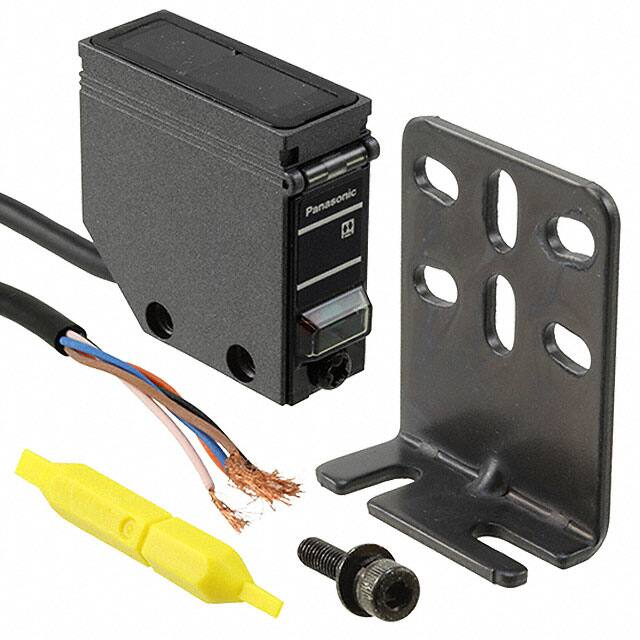
Accessories
• MS-RX-1 (Sensor mounting bracket)
• MS-RX-2 (Sensor mounting bracket)
• PT-RX4-1 (Oil resistant protective tube 1 m 3.281 ft long)
• PT-RX4-2 (Oil resistant protective tube 2 m 6.562 ft long)
• PT-RX4-4 (Oil resistant protective tube 4 m 13.123 ft long)
• RF-230 (Reflector)
• MS-RX-1
• MS-RX-2
Two M4 (Iength 16 mm 0.630 in)
hexagon-socket-head bolts
are attached
Two M4 (Iength 16 mm 0.630 in)
hexagon-socket-head bolts are
attached
SIMPLE
WIRE-SAVING
UNITS
WIRE-SAVING
SYSTEMS
MEASUREMENT
SENSORS
STATIC
CONTROL
DEVICES
LASER
MARKERS
PLC
HUMAN
MACHINE
INTERFACES
ENERGY
MANAGEMENT
SOLUTIONS
FA
COMPONENTS
MACHINE
VISION
SYSTEMS
UV
CURING
SYSTEMS
Selection
Guide
Amplifier
Built-in
Power Supply
Built-in
Amplifierseparated
EX-Z
CX-400
CY-100
EX-10
EX-20
EX-30
EX-40
CX-440
EQ-30
EQ-500
MQ-W
RX-LS200
RX
RT-610
• PT-RX4-□
• RF-230
PT-RX4-□
�Robust Photoelectric Sensor
RX SERIES
352
OPTIONS
Designation
FIBER
SENSORS
Model No.
OS-RX-05×5
Description
Slit on emitter
• Sensing range: �2.7 m 8.858 ft [RX-M10]�
1.4 m 4.593 ft [RX2-M5]
• Min. sensing object: ø8 mm ø0.315 in
Slit on receiver
• Sensing range: �1.9 m 6.234 ft [RX-M10]�
1 m 3.281 ft [RX2-M5]
• Min. sensing object: ø6 mm ø0.236 in
Slit on both sides
• Sensing range: �0.4 m 1.312 ft [RX-M10]�
0.2 m 0.656 ft [RX2-M5]
• Min. sensing object: �0.5 × 5 mm�
0.020 × 0.197 in
Slit on emitter
• Sensing range: �3.8 m 12.467 ft [RX-M10]
1.9 m 6.234 ft [RX2-M5]
• Min. sensing object: ø8 mm ø0.315 in
Slit size 0.5 × 5 mm
0.020 × 0.197 in
OS-RX-5×05
Slit size 5 × 0.5 mm
0.197 × 0.020 in
OS-RX-1×5
Slit size 1 × 5 mm
0.039 × 0.197 in
Slit on receiver
OS-RX-5×1
Slit size 5 × 1 mm
0.197 × 0.039 in
OS-RX-3×5
Slit size 3 × 5 mm
0.118 × 0.197 in
OS-RX-5×3
Slit size 5 × 3 mm
0.197 × 0.118 in
Reflector
For
retroreflective
type sensor only
(Note 1)
Reflector
mounting
bracket
(Note 1)
Reflective tape
For RX-RVM5
only
Protective tube
Sensor checker
(Note 2)
Slit on emitter
• Sensing range: �7 m 22.966 ft [RX-M10]�
3.5 m 11.483 ft [RX2-M5]
• Min. sensing object: ø8 mm ø0.315 in
Slit on receiver
• Sensing range: �4.9 m 16.076 ft [RX-M10]�
2.5 m 8.202 ft [RX2-M5]
• Min. sensing object: ø6 mm ø0.236 in
RF-220
• Sensing range: �0.1 to 3.8 m 0.328 to 12.467 ft [RX-RVM5]�
0.1 to 2 m 0.328 to 6.562 ft [RX-PRVM3]�
0.1 to 1.3 m 0.328 to 4.265 ft [RX2-PRVM2]
• Min. sensing object: ø35 mm ø1.378 in
MS-RF21-1
Protective mounting bracket for RF-210
It protects the reflector from damage and maintains alignment.
MS-RF22
For RF-220
MS-RF23
For RF-230
RF-T110
This tape can be used in place of the reflector by cutting it to a
suitable size.
• Size: 100 × 100 mm 3.937 × 3.937 in
• Sensing range: 3 m 9.843 ft (at 50 × 50 mm 1.969 × 1.969 in)�
(There may be a slight variation depending on the product.)
PT-RX1000
CHX-SC2
OS-RX-1×5
a b
500 mm 19.685 in
1,000 mm 39.370 in
a
MICRO
PHOTOELECTRIC
SENSORS
AREA
SENSORS
SAFETY LIGHT
CURTAINS /
SAFETY
COMPONENTS
Slit mask
Reflector
• RF-210
PRESSURE /
FLOW
SENSORS
• RF-220
33.3 mm
1.311 in
INDUCTIVE
PROXIMITY
SENSORS
11 mm
0.433 in
12.8 mm
0.504 in
8.3 mm
0.327 in
35.3 mm
1.390 in
SIMPLE
WIRE-SAVING
UNITS
WIRE-SAVING
SYSTEMS
MEASUREMENT
SENSORS
Reflector mounting bracket
STATIC
CONTROL
DEVICES
• MS-RF21-1
LASER
MARKERS
Two M3 (length 12 mm 0.472 in)
screws with washers are attached.
• MS-RF22
• MS-RF23
PLC
HUMAN
MACHINE
INTERFACES
ENERGY
MANAGEMENT
SOLUTIONS
FA
COMPONENTS
Two M3
(length 8 mm 0.315 in)
screws with washers
are attached.
MACHINE
VISION
SYSTEMS
Two M4
(length 10 mm 0.394 in)
screws with washers
are attached.
UV
CURING
SYSTEMS
Protective tube
• PT-RX500
• PT-RX1000
Selection
Guide
Amplifier
Built-in
Power Supply
Built-in
Protective tube
Cable is protected from external forces.
It does not rust as it is made of
stainless steel.
Amplifierseparated
EX-Z
It is useful for beam alignment of thru-beam type sensors. The
optimum receiver position is given by indicators, as well as an
audio signal.
Notes: 1) Refer to CX-400 series pages (p.269 and p.272) for dimensions of the reflector or the reflector
mounting bracket.
2) Refer to p.959~ for the sensor checker.
PARTICULAR
USE
SENSORS
SENSOR
OPTIONS
42.3 mm
1.665 in
• Sensing range: �2.6 m 8.530 ft [RX-M10]�
1.3 m 4.265 ft [RX2-M5]
Slit on both sides
• Min. sensing object: �3 × 5 mm�
0.118 × 0.197 in
RF-210
PHOTOELECTRIC
SENSORS
b
*Slit size
• Sensing range: �2.8 m 9.186 ft [RX-M10]�
1.4 m 4.593 ft [RX2-M5]
• Min. sensing object: ø6 mm ø0.236 in
• Sensing range: �0.2 to 1.5 m 0.656 to 4.921 ft [RX-RVM5]�
0.4 to 1 m 1.312 to 3.281 ft [RX-PRVM3]
• Min. sensing object: ø30 mm ø1.181 in
PT-RX500
• OS-RX-□
Fitted on the front
face of the sensor
with one-touch.
• Sensing range: �0.8 m 2.625 ft [RX-M10]�
0.4 m 1.312 ft [RX2-M5]
Slit on both sides • Min. sensing object: �1 × 5 mm�
0.039 × 0.197 in
Length
Slit mask
For RX-M10
and RX2-M5
only
LASER
SENSORS
Slit mask
CX-400
CY-100
EX-10
Sensor checker
EX-20
• CHX-SC2
EX-30
EX-40
CX-440
PO
W
ER
C
H
LE
VE
L
X-
SC
2
EQ-30
EQ-500
Sensor checker
MQ-W
RX-LS200
RX
RT-610
�353
Robust Photoelectric Sensor
SPECIFICATIONS
FIBER
SENSORS
LASER
SENSORS
Standard type
Thru-beam
PHOTOELECTRIC
SENSORS
MICRO
PHOTOELECTRIC
SENSORS
AREA
SENSORS
SAFETY LIGHT
CURTAINS /
SAFETY
COMPONENTS
PRESSURE /
FLOW
SENSORS
INDUCTIVE
PROXIMITY
SENSORS
PARTICULAR
USE
SENSORS
SENSOR
OPTIONS
SIMPLE
WIRE-SAVING
UNITS
WIRE-SAVING
SYSTEMS
RX SERIES
Type
Infrared
Model No.
RX-M10
RX-M50
Sensing object
50 m
164.042 ft
Repeatability
(perpendicular to sensing axis)
UV
CURING
SYSTEMS
Selection
Guide
Amplifier
Built-in
Power Supply
Built-in
Amplifierseparated
CX-400
CY-100
MQ-W
RX
RX-D700
RX-D200R
0.1 to 5 m
700 mm
200 mm
0.1 to 3 m
0.328 to 9.843 ft (Note 2) 0.328 to 16.404 ft (Note 2) 27.559 in (Note 3) 7.874 in (Note 3)
ø50 mm ø1.969 in or
more opaque,
translucent or specular
object (Note 2, 5)
ø50 mm ø1.969 in
or more opaque,
or translucent
object (Note 2, 5)
Opaque, translucent or
transparent object (Note 5)
15 % or less of operation distance (Note 3)
0.5 mm 0.020 in or less
1 mm 0.039 in or less
0.5 mm 0.020 in or less
Emitter: 20 mA or less (RX-M50: 25 mA or less), Receiver: 25 mA or less
40 mA or less
NPN open-collector transistor
• Maximum sink current: 100 mA
• Applied voltage: 30 V DC or less (between sensing output and 0 V)
• Residual voltage: �2 V or less (at 100 mA sink current)�
1 V or less (at 16 mA sink current)
DC-12 or DC-13
Switchable either Light-ON or Dark-ON
Incorporated
NPN open-collector transistor
• Maximum sink current: 50 mA
• Applied voltage: 30 V DC or less (between self-diagnosis output and 0 V)
• Residual voltage: �1.5 V or less (at 50 mA sink current)�
1 V or less (at 16 mA sink current)
Self-diagnosis output
Output operation
ON under unstable sensing condition
–
Short-circuit protection
Response time
1 ms or less
Test input (emission halt) function
Incorporated
Operation indicator
Red LED (lights up when the sensing output is ON)
Stability indicator
Green LED (lights up under stable light received condition or stable dark condition)
–
Red LED (lights up during beam emission)
Emitting indicator
Sensitivity adjuster
Continuously variable adjuster
–
Automatic interference prevention function
Incorporated (Two units of sensors can be mounted close together.)
Pollution degree
3 (Industrial environment)
Protection
IP67 (IEC)
Ambient temperature
–25 to +60 °C –13 to +140 °F (No dew condensation or icing allowed), Storage: –30 to +70 °C –22 to +158 °F
Ambient humidity
35 to 85 % RH, Storage: 35 to 85 % RH
Ambient illuminance
Incandescent light: 3,500 ℓx or less at the light-receiving face
Voltage withstandability
1,000 V AC for one min. between all supply terminals connected together and enclosure
Insulation resistance
20 MΩ, or more, with 250 V DC megger between all supply terminals connected together and enclosure
Vibration resistance
10 to 500 Hz frequency, 1.5 mm 0.059 in double amplitude (10 G max.) in X, Y and Z directions for two hours each
Shock resistance
500 m/s2 acceleration (50 G approx.) in X, Y and Z directions three times each
Peak emission wavelength
Material
Infrared LED
Red LED
Green LED
Red LED
Infrared LED
Red LED
880 nm 0.035 mil
660 nm 0.026 mil
570 nm 0.022 mil
680 nm 0.027 mil
880 nm 0.035 mil
680 nm 0.027 mil
Enclosure: Die-cast zinc alloy, Indicator cover: Polyethersulphone, Lens: Polycarbonate (Retroreflective type: Acrylic)
Emitter: 0.15 mm2 3-core oil, heat and cold resistant cabtyre cable, 2 m 6.562 ft long
Receiver: 0.15 mm2 4-core oil, heat and cold resistant cabtyre cable, 2 m 6.562 ft long
Cable
0.15 mm2 5-core oil, heat and cold resistant cabtyre cable,
2 m 6.562 ft long
Extension up to total 100 m 328.084 ft is possible with 0.3 mm2, or more, cable (thru-beam type: both emitter and receiver).
Emitter: 70 g approx. (RX-M50: 75 g approx.)
Receiver: 70 g approx. (RX-M50: 75 g approx.)
EX-30
RX-LS200
RX-RVM5
Short-circuit protection
Net weight
EQ-500
RX-PRVM3
500 mm
19.685 in
Output operation
EX-20
EQ-30
RX-500G
Utilization category
Cable extension
CX-440
Red
–
Sensing output
EX-10
EX-40
Infrared
12 to 24 V DC ±10 % Ripple P-P 10 % or less
Current consumption
Emitting element (modulated)
EX-Z
2m
6.562 ft
Supply voltage
Environmental resistance
MACHINE
VISION
SYSTEMS
Infrared
(Long sensing range)
–
LASER
MARKERS
FA
COMPONENTS
Green
ø10 mm 0.394 in or more opaque object (Note 4)
Hysteresis
HUMAN
MACHINE
INTERFACES
Diffuse reflective
EMC Directive, RoHS Directive
10 m
32.808 ft
Sensing range
STATIC
CONTROL
DEVICES
ENERGY
MANAGEMENT
SOLUTIONS
RX-M2R
CE marking directive compliance
MEASUREMENT
SENSORS
PLC
Red
Long sensing range
Item
Retroreflective
Red
with polarizing filters
75 g approx.
MS-RX-1 (Sensor mounting bracket): 1 set
MS-RX-1 (Sensor mounting bracket):
1 set for emitter and receiver RF-230 (Reflector): 1 pc.
Adjusting screwdriver: 1 pc.
Adjusting screwdriver: 1 pc.
Accessories
Notes: 1) Where measurement conditions have not been specified precisely, the conditions used
were an ambient temperature of +23 °C +73.4 °F.
2) The sensing range and the sensing object for the retroreflective type sensor are specified for
the RF-230 reflector. Further, the sensing range of RX-PRVM3 and RX-RVM5 is the possible
setting range for the reflector. The sensor can detect an object less than 0.1 m 0.328 ft away.
Reflector cannot
be placed in this
range
RT-610
Sensor
Actual sensing range
of the sensor
0.1 m 0.328 ft
Setting range
of the reflector
( RX-PRVM3:
3 m 9.843 ft )
Reflector
Reflector
5 m 16.404 ft
MS-RX-1 (Sensor mounting
bracket): 1 set
Adjusting screwdriver: 1 pc.
3) The sensing range and the hysteresis of the diffuse
reflective type sensor are specified for white non-glossy
paper (200 × 200 mm 7.874 × 7.874 in) as the object.
4) If slit masks (optional) are fitted on RX-M10, an object
of 0.5 × 5 mm 0.020 × 0.197 in can be detected.
5) Make sure to confirm detection with an actual sensor
before use.
�Robust Photoelectric Sensor
RX SERIES
SPECIFICATIONS
354
FIBER
SENSORS
LASER
SENSORS
DC 2-wire type
Type
PHOTOELECTRIC
SENSORS
Thru-beam
Retroreflective (with polarizing filters)
Diffuse reflective
RX2-M5
RX2-PRVM2
RX2-D300
Sensing range
5 m 16.404 ft
0.1 to 2 m 0.328 to 6.562 ft (Note 2)
300 mm 11.811 in (Note 3)
Sensing object
ø10 mm ø0.394 in or more opaque
object (Note 4)
ø50 mm ø1.969 in or more opaque,
translucent or specular object (Note 2, 5)
Opaque, translucent or transparent
object (Note 5)
AREA
SENSORS
–
–
15 % or less of operation distance (Note 3)
SAFETY LIGHT
CURTAINS /
SAFETY
COMPONENTS
0.5 mm 0.020 in or less
1 mm 0.039 in or less
0.5 mm 0.020 in or less
Item
Model No.
Hysteresis
Repeatability
(perpendicular to sensing axis)
Supply voltage
12 to 24 V DC ±10 % Ripple P-P 10 % or less
Current consumption
Emitter: 8 mA or less, Receiver: 0.8 mA or less (Note 6)
Output operation
SENSOR
OPTIONS
SIMPLE
WIRE-SAVING
UNITS
Incorporated
Response time
3 ms or less
Operation indicator
WIRE-SAVING
SYSTEMS
Red LED (lights up when the output is ON)
Light-ON mode: lights up under stable light received condition
Green LED Dark-ON mode: lights up under stable dark condition
Stability indicator
Emitting indicator
–
Red LED (lights up during beam emission)
Sensitivity adjuster
Continuously variable adjuster
Protection
Environmental resistance
PARTICULAR
USE
SENSORS
Switchable either Light-ON or Dark-ON
Short-circuit protection
–20 to +60 °C –4 to +140 °F (No dew condensation or icing allowed), Storage: –30 to +70 °C –22 to +158 °F
Ambient humidity
35 to 85 % RH, Storage: 35 to 85 % RH
Ambient illuminance
1,000 V AC for one min. between all supply terminals connected together and enclosure
Insulation resistance
20 MΩ, or more, with 250 V DC megger between all supply terminals connected together and enclosure
Vibration resistance
10 to 500 Hz frequency, 1.5 mm 0.059 in double amplitude (10 G max.) in X, Y and Z directions for two hours each
500 m/s2 acceleration (50 G approx.) in X, Y and Z directions three times each
Shock resistance
Emitting element
Peak emission wavelength
Material
STATIC
CONTROL
DEVICES
PLC
HUMAN
MACHINE
INTERFACES
Incandescent light: 3,500 ℓx or less at the light-receiving face
Voltage withstandability
MEASUREMENT
SENSORS
LASER
MARKERS
IP67 (IEC)
Ambient temperature
PRESSURE /
FLOW
SENSORS
INDUCTIVE
PROXIMITY
SENSORS
1 mA or less (Note 6)
Non contact DC 2-wire type
• Load current: 5 to 100 mA
• Residual voltage: 4 V or less (Note 7)
Sensing output
MICRO
PHOTOELECTRIC
SENSORS
Infrared LED (modulated)
Red LED (modulated)
Infrared LED (modulated)
880 nm 0.035 mil
680 nm 0.027 mil
890 nm 0.035 mil
ENERGY
MANAGEMENT
SOLUTIONS
FA
COMPONENTS
MACHINE
VISION
SYSTEMS
UV
CURING
SYSTEMS
Enclosure: Die-cast zinc alloy, Indicator cover: Polyethersulphone, Lens: Polycarbonate (RX2-PRVM2: Acrylic)
0.15 mm2 2-core oil, heat and cold resistant cabtyre cable, 2 m 6.562 ft long
Cable
– (Note 7)
Cable extension
Selection
Guide
Net weight
Emitter: 70 g approx., Receiver: 70 g approx.
Accessories
MS-RX-1 (Sensor mounting bracket):
MS-RX-1 (Sensor mounting bracket): 1 set
MS-RX-1 (Sensor mounting bracket): 1 set
1 set for emitter and receiver RF-230 (Reflector): 1 pc.
Adjusting screwdriver: 1 pc.
Adjusting screwdriver: 1 pc.
Adjusting screwdriver: 1 pc.
75 g approx.
70 g approx.
Notes: 1) Where measurement conditions have not been specified precisely, the conditions used were an ambient temperature of +23 °C +73.4 °F.
2) The sensing range and the sensing object for RX2-PRVM2 are specified for the RF-230 reflector. Further, the sensing range is the possible setting
range for the reflector. The sensor can detect an object less than 0.1 m 0.328 ft away.
Reflector cannot
be placed in this
range
Sensor
Actual sensing range
of the sensor
0.1 m 0.328 ft
Setting range
of the reflector
Reflector
2m
6.562 ft
Amplifier
Built-in
Power Supply
Built-in
Amplifierseparated
EX-Z
CX-400
CY-100
EX-10
Reflector
3) The sensing range and the hysteresis of RX2-D300 are specified for white non-glossy paper (200 × 200 mm 7.874 × 7.874 in) as the object.
4) If slit masks (optional) are fitted, an object of 0.5 × 5 mm 0.020 × 0.197 in can be detected.
5) Make sure to confirm detection with an actual sensor before use.
6) It is the leakage current when the output is in the OFF state.
7) When extending the cable, the residual voltage will be increased depending on the type of cable used. Verify the residual voltage when extending the
cable.
EX-20
EX-30
EX-40
CX-440
EQ-30
EQ-500
MQ-W
RX-LS200
RX
RT-610
�355
Robust Photoelectric Sensor
SPECIFICATIONS
FIBER
SENSORS
LASER
SENSORS
Heavy duty type
PHOTOELECTRIC
SENSORS
MICRO
PHOTOELECTRIC
SENSORS
AREA
SENSORS
SAFETY LIGHT
CURTAINS /
SAFETY
COMPONENTS
PRESSURE /
FLOW
SENSORS
INDUCTIVE
PROXIMITY
SENSORS
PARTICULAR
USE
SENSORS
RX SERIES
Type
Item
Model No.
Thru-beam
Cable length 2 m 6.562 ft
Cable length 3 m 9.843 ft
Cable length 5 m 16.404 ft
RX4-M5
RX4-M5-C3
RX4-M5-C5
Sensing range
5 m 16.404 ft
Sensing object
ø10 mm ø0.394 in or more opaque object
Repeatability
(perpendicular to sensing axis)
0.5 mm 0.020 in or less
Supply voltage
12 to 24 V DC ±10 % Ripple P-P 10 % or less
Current consumption
Emitter: 20 mA or less, Receiver: 25 mA or less
NPN open-collector transistor
• Maximum sink current: 100 mA
• Applied voltage: 30 V DC or less (between sensing output and 0 V)
• Residual voltage: �2 V or less (at 100 mA sink current)�
1 V or less (at 16 mA sink current)
Sensing output
SENSOR
OPTIONS
SIMPLE
WIRE-SAVING
UNITS
Output operation
Short-circuit protection
WIRE-SAVING
SYSTEMS
MEASUREMENT
SENSORS
Self-diagnosis output
STATIC
CONTROL
DEVICES
ENERGY
MANAGEMENT
SOLUTIONS
FA
COMPONENTS
MACHINE
VISION
SYSTEMS
UV
CURING
SYSTEMS
Selection
Guide
Amplifier
Built-in
Power Supply
Built-in
Amplifierseparated
CX-400
CY-100
EX-10
EX-20
EX-30
EX-40
CX-440
EQ-30
EQ-500
MQ-W
RX-LS200
RX
RT-610
–
Short-circuit protection
1 ms or less
Test input (emission halt) function
Incorporated
Operation indicator
Red LED (lights up when the sensing output is ON)
Stability indicator
Green LED (lights up under stable light received condition or stable dark condition)
Emitting indicator
Red LED (lights up during beam emission)
Sensitivity adjuster
Continuously variable adjuster
Protection
Ambient temperature
IP67 (IEC), IP67G
–25 to +60 °C –13 to +140 °F (No dew condensation or icing allowed), Storage: –30 to +70 °C –22 to +158 °F
Ambient humidity
35 to 85 % RH, Storage: 35 to 85 % RH
Ambient illuminance
Voltage withstandability
Incandescent light: 3,500 ℓx or less at the light-receiving face
1,000 V AC for one min. between all supply terminals connected together and enclosure
Insulation resistance
20 MΩ, or more, with 250 V DC megger between all supply terminals connected together and enclosure
Vibration resistance
10 to 500 Hz frequency, 1.5 mm 0.059 in double amplitude (10 G max.) in X, Y and Z directions for two hours each
Shock resistance
500 m/s2 acceleration (50 G approx.) in X, Y and Z directions three times each
Emitting element
Material
EX-Z
ON under unstable sensing condition
Response time
Environmental resistance
HUMAN
MACHINE
INTERFACES
Incorporated
NPN open-collector transistor
• Maximum sink current: 50 mA
• Applied voltage: 30 V DC or less (between self-diagnosis output and 0 V)
• Residual voltage: �1.5 V or less (at 50 mA sink current)�
1 V or less (at 16 mA sink current)
Output operation
LASER
MARKERS
PLC
Switchable either Light-ON or Dark-ON
Cable
Protective tube length
Cable extension
Net weight
Accessories
Infrared LED (Peak emission wavelength: 880 nm 0.035 mil, modulated)
Enclosure: Die-cast zinc alloy (Fluorine resin coating), Indicator cover: Polyethersulphone,
Lens: Polyalylate, Protective tube sheath: Oil resistant PVC
0.15 mm2 4-core (emitter: 3-core) oil, heat and cold resistant cabtyre cable
1 m 3.281 ft
2 m 6.562 ft
4 m 13.123 ft
Extension up to total 100 m 328.084 ft is possible for both emitter and receiver with 0.3 mm2, or more, cable.
Emitter: 175 g approx., Receiver: 175 g approx. Emitter: 265 g approx., Receiver: 265 g approx. Emitter: 495 g approx., Receiver: 495 g approx.
MS-RX-2 (Sensor mounting bracket): 1 set for emitter and receiver, Adjusting screwdriver: 1 pc.
Note: Where measurement conditions have not been specified precisely, the conditions used were an ambient temperature of +23 °C +73.4 °F.
�Robust Photoelectric Sensor
RX SERIES
I/O CIRCUIT AND WIRING DIAGRAMS
FIBER
SENSORS
LASER
SENSORS
RX-□ RX4-□
I/O circuit diagrams
PHOTOELECTRIC
SENSORS
Wiring diagram
Emitter of thru-beam type sensor
Emitter of thru-beam type sensor
MICRO
PHOTOELECTRIC
SENSORS
Color code
Sensor circuit
D
(Brown) +V
(Pink) Test input
1 mA max. (emission halt input)
AREA
SENSORS
Brown
*1
+
–
12 to 24 V DC
±10 %
Pink
*1
+
–
(Blue) 0 V
Internal circuit
356
12 to 24 V DC
±10 %
* 1
PARTICULAR
USE
SENSORS
Non-voltage contact or NPN open-collector transistor
Symbol … D: Reverse supply polarity protection diode
PRESSURE /
FLOW
SENSORS
INDUCTIVE
PROXIMITY
SENSORS
Blue
Users’ circuit
SAFETY LIGHT
CURTAINS /
SAFETY
COMPONENTS
SENSOR
OPTIONS
or
SIMPLE
WIRE-SAVING
UNITS
• Test input (emission halt input)
[Supply voltage – 2.5 V] or more: Emission
[Supply voltage – 3.3 V] or less: Emission halt
WIRE-SAVING
SYSTEMS
MEASUREMENT
SENSORS
Receiver of thru-beam type sensor
Color code
D1
Sensor circuit
Tr2
Load
Load
100mA max.
Black
Load
ZD1
D3 (Orange) Self-diagnosis output (Note)
+
–
PLC
Load
+
12 to 24 V DC
±10 %
–
Orange
12 to 24 V DC
±10 %
FA
COMPONENTS
Blue
(Blue) 0 V
HUMAN
MACHINE
INTERFACES
ENERGY
MANAGEMENT
SOLUTIONS
50 mA max.
ZD2
Internal circuit
LASER
MARKERS
Brown
(Brown) +V
D2 (Black) Sensing output
Tr1
STATIC
CONTROL
DEVICES
Receiver of thru-beam type sensor
MACHINE
VISION
SYSTEMS
Users’ circuit
Note: The self-diagnosis output does not incorporate a short-circuit protection
circuit. Do not connect it directly to a power supply or a capacitive load.
UV
CURING
SYSTEMS
Symbols ... �D1: Reverse supply polarity protection diode
D2, D3 : Reverse output polarity protection diode
ZD1, ZD2: Surge absorption zener diode
Tr1, Tr2 : NPN output transistor
Selection
Guide
Retroreflective and diffuse reflective type sensors
Color code
D1
Sensor circuit
*1
Black
Tr2
ZD2
Internal circuit
Amplifierseparated
Load
Load
Load
D2 (Black) Sensing output
Tr1
Power Supply
Built-in
Brown
(Brown) +V
(Pink) Test input
1mA max. (emission halt input)
Amplifier
Built-in
Retroreflective and diffuse reflective type sensors
Load +
100 mA max.
ZD1
D3 (Orange) Self-diagnosis output (Note)
–
Pink
(Blue) 0 V
Users’ circuit
Symbols ... �D1: Reverse supply polarity protection diode
D2, D3 : Reverse output polarity protection diode
ZD1, ZD2: Surge absorption zener diode
Tr1, Tr2 : NPN output transistor
12 to 24 V DC
±10 %
EX-Z
CX-400
CY-100
Blue
50 mA max.
Note: The self-diagnosis output does not incorporate a short-circuit protection
circuit. Do not connect it directly to a power supply or a capacitive load.
–
Orange
12 to 24 V DC
±10 %
+
EX-10
*1
EX-20
EX-30
* 1
EX-40
Non-voltage contact or NPN open-collector transistor
CX-440
EQ-30
or
• Test input (emission halt input)
[Supply voltage – 2.5 V] or more: Emission
[Supply voltage – 3.3 V] or less: Emission halt
EQ-500
MQ-W
RX-LS200
RX
RT-610
�357
Robust Photoelectric Sensor
I/O CIRCUIT AND WIRING DIAGRAMS
FIBER
SENSORS
LASER
SENSORS
PHOTOELECTRIC
SENSORS
MICRO
PHOTOELECTRIC
SENSORS
RX2-□
I/O circuit diagrams
(Brown) +V
Sensor circuit
PRESSURE /
FLOW
SENSORS
+
–
+
–
12 to 24 V DC
±10 %
Blue
Internal circuit
PARTICULAR
USE
SENSORS
Users’ circuit
Symbol … D: Reverse supply polarity protection diode
Receiver of thru-beam type sensor, retroreflective and diffuse
reflective type sensors
Receiver of thru-beam type sensor, retroreflective and diffuse
reflective type sensors
Color code
Bleeder resistance
WIRE-SAVING
SYSTEMS
(Brown) Output
Sensor circuit
STATIC
CONTROL
DEVICES
Brown
12 to 24 V DC
±10 %
(Blue) 0 V
INDUCTIVE
PROXIMITY
SENSORS
MEASUREMENT
SENSORS
Emitter of thru-beam type sensor
Color code
D
SAFETY LIGHT
CURTAINS /
SAFETY
COMPONENTS
SIMPLE
WIRE-SAVING
UNITS
Wiring diagrams
Emitter of thru-beam type sensor
AREA
SENSORS
SENSOR
OPTIONS
RX SERIES
Tr
ZD
LASER
MARKERS
Load
Brown
5 to 100 mA in the ON state +
4 V in the 1 mA in the OFF state
ON state
–
Receiver of thru-beam
type sensor: 0.8 mA
(Blue) 0 V
Internal circuit
(
)
12 to 24 V DC
±10 %
Load
+
–
12 to 24 V DC
±10 %
Blue
Users’ circuit
PLC
Symbols ... D : Reverse supply polarity protection diode
ZD: Surge absorption zener diode
Tr : PNP output transistor
HUMAN
MACHINE
INTERFACES
ENERGY
MANAGEMENT
SOLUTIONS
Conditions for the load
FA
COMPONENTS
1) T
� he load should not be actuated by the leakage current (1 mA; 0.8 mA
for receiver of thru-beam type sensor) in the OFF state.
2) T
� he load should be actuated by (supply voltage – 4 V) in the ON state.
3) �The current in the ON state should be between 5 to 100 mA DC.
In case the current is less than 5 mA, connect a bleeder
resistance in parallel to the load (shown in dotted line above) so
that a current of 5 mA, or more, flows.
MACHINE
VISION
SYSTEMS
UV
CURING
SYSTEMS
SENSING CHARACTERISTICS (TYPICAL)
Selection
Guide
Amplifierseparated
EX-Z
RX-□
Correlation between setting distance and excess gain
100
100
100
50
50
50
EX-10
EX-20
Excess gain
CX-400
CY-100
All models
RX-M50
10
5
EX-30
EQ-30
EQ-500
MQ-W
RX-LS200
RX
RT-610
10
RX-PRVM3
5
1
0
20
60
80
100
40
65.617 131.234 196.850 262.467 328.084
Setting distance L (m ft)
RX-D700
10
RX-500G
5
RX-D300
RX-M2R
RX-M10
EX-40
CX-440
RX-RVM5
Excess gain
Power Supply
Built-in
Excess gain
Amplifier
Built-in
1
0
2
4
6
8
10
6.562 13.123 19.685 26.247 32.808
Setting distance L (m ft)
RX-D200R
1
0
200
400
600
800 1,000
7.874 15.748 23.622 31.496 39.370
Setting distance L (mm in)
�Robust Photoelectric Sensor
RX SERIES
358
SENSING CHARACTERISTICS (TYPICAL)
FIBER
SENSORS
RX-M10
Thru-beam type
Parallel deviation with slit masks
(1 × 5 mm 0.039 × 0.197 in)
Emitter
5
16.404
ℓ
Receiver
200
0
200
400
7.874
7.874 15.748
Left
Center
Right
Operating point ℓ (mm in)
RX-M50
3
9.843
2 Slit on
6.562 emitter
0
200
7.874
Parallel deviation
ℓ
L
Receiver
100
0
100
200
3.937
3.937
7.874
Left
Center
Right
Operating point ℓ (mm in)
RX-M2R
Thru-beam type
Emitter
Slit on
1 receiver
3.281
Slit on
both sides
Parallel deviation
Emitter
1
3.281
ℓ
L
Slit on
4 receiver
Emitter
13.123
Slit on
both side
2
ℓ L
6.562
Slit on
emitter
Receiver
0
400
200
0
200
400
15.748 7.874
7.874
15.748
Left
Center
Right
Operating point ℓ (mm in)
Receiver
100
0
100
200
7.874
3.937
3.937
Left
Center
Right
Operating point ℓ (mm in)
RX4-M5□
Thru-beam type
Parallel deviation
40
131.234
Emitter
20
65.617
ℓ
L
Receiver
Emitter
1
3.281
ℓ
L
400
15.748
Receiver
100
0
100
200
7.874
3.937
3.937
Left
Center
Right
Operating point ℓ (mm in)
Emitter
ℓ
200
7.874
0
40
1.575
L
Emitter
2
6.562
0
400
15.748
Receiver
200
0
200
400
7.874
7.874 15.748
Left
Center
Right
Operating point ℓ (mm in)
Thru-beam type
L
Emitter
Slit on
receiver
ℓ
Slit on
both sides
0
100
3.937
L
Receiver
50
0
50
100
1.969
1.969
3.937
Left
Center
Right
Operating point ℓ (mm in)
Slit on
receiver
1
3.281
Emitter
0.5 Slit on
1.640 both sides
ℓ
L
Receiver
50
0
50
100
1.969
1.969
3.937
Left
Center
Right
Operating point ℓ (mm in)
RX-RVM5 Retroreflective type
RX2-PRVM2 Retroreflective type
Parallel deviation
Parallel deviation
ℓ
L
Sensor
50
0
50
100
1.969
1.969
3.937
Left
Center
Right
Operating point ℓ (mm in)
4
13.123
2
6.562
0
100
3.937
PARTICULAR
USE
SENSORS
SENSOR
OPTIONS
SIMPLE
WIRE-SAVING
UNITS
Slit on
emitter
LASER
MARKERS
PLC
HUMAN
MACHINE
INTERFACES
ENERGY
MANAGEMENT
SOLUTIONS
FA
COMPONENTS
MACHINE
VISION
SYSTEMS
UV
CURING
SYSTEMS
3
9.843
2
6.562
1
3.281
Emitter
Slit on
receiver
Slit on
both sides
0
200
7.874
ℓ
L
Receiver
100
0
100
200
3.937
3.937
7.874
Left
Center
Right
Operating point ℓ (mm in)
Selection
Guide
Amplifier
Built-in
Power Supply
Built-in
Amplifierseparated
EX-Z
CX-400
CY-100
EX-20
EX-30
6
19.685
Reflector
(RF-230)
INDUCTIVE
PROXIMITY
SENSORS
EX-10
8
26.247
3
9.843
Parallel deviation with slit masks
(3 × 5 mm 0.118 × 0.197 in)
4
13.123
Slit on
emitter
1.5
4.921
0
100
3.937
Reflector
(RF-230)
ℓ
L
Sensor
50
0
50
100
1.969
1.969
3.937
Left
Center
Right
Operating point ℓ (mm in)
Setting distance L (m ft)
Setting distance L (m ft)
4
13.123
0
100
3.937
0.5
1.640
Receiver
200
200
400
0
7.874
7.874 15.748
Left
Center
Right
Operating point ℓ (mm in)
Parallel deviation
Slit on
emitter
1
3.281
Setting distance L (m ft)
ℓ
RX-PRVM3 Retroreflective type
1
3.281
Setting distance L (m ft)
Emitter
2
6.562
2
6.562
2
6.562
1.5
4.921
Setting distance L (m ft)
Setting distance L (m ft)
2
6.562
6
19.685
0
400
15.748
Parallel deviation with slit masks
(1 × 5 mm 0.039 × 0.197 in)
Setting distance L (m ft)
Parallel deviation with slit masks
(0.5 × 5 mm 0.020 × 0.197 in)
8
26.247
4
13.123
L
ℓ
RX2-M5
Parallel deviation
PRESSURE /
FLOW
SENSORS
STATIC
CONTROL
DEVICES
4
13.123
Receiver
SAFETY LIGHT
CURTAINS /
SAFETY
COMPONENTS
MEASUREMENT
SENSORS
6
19.685
20
0
20
40
0.787
0.787
1.575
Left
Center
Right
Operating point ℓ (mm in)
MICRO
PHOTOELECTRIC
SENSORS
WIRE-SAVING
SYSTEMS
8
26.247
600
23.622
0
200
7.874
500
0
500
1,000
19.685
19.685 39.370
Left
Center
Right
Operating point ℓ (mm in)
Setting distance L (m ft)
60
196.850
2
6.562
Thru-beam type
Parallel deviation
800
31.496
Setting distance L (m ft)
Setting distance L (m ft)
2
6.562 Slit on
both sides
PHOTOELECTRIC
SENSORS
AREA
SENSORS
6
19.685
Slit on
receiver
RX-500G
80
262.467
0
1,000
39.370
Slit on
emitter
3
9.843
0
200
7.874
Thru-beam type
8
26.247
Setting distance L (m ft)
0
400
15.748
L
4
13.123
Setting distance L (m ft)
10
32.808
Setting distance L (m ft)
Setting distance L (m ft)
4
13.123
Parallel deviation with slit masks
(3 × 5 mm 0.118 × 0.197 in)
Setting distance L (m ft)
Parallel deviation with slit masks
(0.5 × 5 mm 0.020 × 0.197 in)
Parallel deviation
LASER
SENSORS
EX-40
2
6.562
CX-440
EQ-30
1
3.281
Reflector
(RF-230)
ℓ
L
EQ-500
MQ-W
RX-LS200
0
100
3.937
Sensor
50
0
50
100
1.969
1.969
3.937
Left
Center
Right
Operating point ℓ (mm in)
RX
RT-610
�359
Robust Photoelectric Sensor
SENSING CHARACTERISTICS (TYPICAL)
FIBER
SENSORS
MICRO
PHOTOELECTRIC
SENSORS
AREA
SENSORS
SAFETY LIGHT
CURTAINS /
SAFETY
COMPONENTS
PRESSURE /
FLOW
SENSORS
INDUCTIVE
PROXIMITY
SENSORS
RX-D700
Sensing field
800
31.496
SIMPLE
WIRE-SAVING
UNITS
Correlation between sensing object size and sensing range
200 × 200 mm
7.874 × 7.874 in
White nonglossy paper
600
23.622
ℓ L
400
15.748
Sensor
200
7.874
0
20
0.787
PARTICULAR
USE
SENSORS
SENSOR
OPTIONS
Diffuse reflective type
800
31.496
As the sensing object size becomes smaller than the standard
size (white non-glossy paper 200 × 200 mm 7.874 × 7.874 in), the
sensing range shortens, as shown in the left graph.
600
23.622
Sensing range L (mm in)
PHOTOELECTRIC
SENSORS
Setting distance L (mm in)
LASER
SENSORS
RX SERIES
400
15.748
a × a mm
a × a in
White nonglossy paper
200
7.874
L
10
0
10
20
0.394
0.394
0.787
Left
Center
Right
Operating point ℓ (mm in)
0
Sensor
50
100
150
200
1.969
3.937
5.906
7.874
White non-glossy paper
side length a (mm in)
RX-D200R
Diffuse reflective type
Sensing field
Correlation between sensing object size and sensing range
WIRE-SAVING
SYSTEMS
PLC
100
3.937
20
0.787
MACHINE
VISION
SYSTEMS
UV
CURING
SYSTEMS
Selection
Guide
Amplifier
Built-in
Power Supply
Built-in
Amplifierseparated
EX-Z
As the sensing object size becomes smaller than the standard
size (white non-glossy paper 200 × 200 mm 7.874 × 7.874 in), the
sensing range shortens, as shown in the left graph.
For plotting the left graph, the sensitivity has been set such
that a 200 × 200 mm 7.874 × 7.874 in white non-glossy
paper is just detectable at a distance of 200 mm 7.874 in.
L
Sensor
0
10
0
10
20
0.394
0.394
0.787
Left
Center
Right
Operating point ℓ (mm in)
50
100
150
1.969
3.937
5.906
White non-glossy paper
side length a (mm in)
200
7.874
RX2-D300
Diffuse reflective type
Sensing field
Correlation between sensing object size and sensing range
400
15.748
Setting distance L (mm in)
FA
COMPONENTS
L
100
3.937
a × a mm
a × a in
White nonglossy paper
Sensor
0
HUMAN
MACHINE
INTERFACES
ENERGY
MANAGEMENT
SOLUTIONS
ℓ
Sensing range L (mm in)
LASER
MARKERS
200 × 200 mm
7.874 × 7.874 in
White nonglossy paper
400
15.748
300
11.811
300
11.811
200
7.874
200 × 200 mm
7.874 × 7.874 in
White nonglossy paper
100
3.937
ℓ
0
20
0.787
L
Sensor
10
0
10
20
0.394
0.394
0.787
Left
Center
Right
Operating point ℓ (mm in)
Sensing range L (mm in)
STATIC
CONTROL
DEVICES
200
7.874
200
7.874
Setting distance L (mm in)
MEASUREMENT
SENSORS
For plotting the left graph, the sensitivity has been set such
that a 200 × 200 mm 7.874 × 7.874 in white non-glossy
paper is just detectable at a distance of 700 mm 27.559 in.
200
7.874
a × a mm
a × a in
White nonglossy paper
100
3.937
0
As the sensing object size becomes smaller than the standard
size (white non-glossy paper 200 × 200 mm 7.874 × 7.874 in), the
sensing range shortens, as shown in the left graph.
For plotting the left graph, the sensitivity has been set such
that a 200 × 200 mm 7.874 × 7.874 in white non-glossy
paper is just detectable at a distance of 300 mm 11.811 in.
L
Sensor
50
100
150
200
1.969
3.937
5.906
7.874
White non-glossy paper
side length a (mm in)
PRECAUTIONS FOR PROPER USE
Refer to p.1552~ for general precautions.
CX-400
CY-100
• Never use this product as a sensing device
for personnel protection.
• In case of using sensing devices for
personnel protection, use products which
meet laws and standards, such as OSHA,
ANSI or IEC etc., for personnel protection
applicable in each region or country.
EX-10
EX-20
EX-30
EX-40
CX-440
EQ-30
EQ-500
MQ-W
RX-LS200
RX
RT-610
Wiring
• The self-diagnosis output does not incorporate a shortcircuit protection circuit. Do not connect it directly to a
power supply or a capacitive load.
Mounting
• The tightening
torque should
be 1.17 N·m or
less.
M4 (length 16 mm 0.630 in)
hexagon-socket-head bolt
Attached mounting bracket
Others
• Do not use during the initial transient time (50 ms) after
the power supply is switched on.
�Robust Photoelectric Sensor
PRECAUTIONS FOR PROPER USE
RX SERIES
360
Refer to p.1552~ for general precautions.
• Do not connect sensors in series (AND circuit).
RX-RVM5
FIBER
SENSORS
LASER
SENSORS
PHOTOELECTRIC
SENSORS
Glossy object sensing
• Please take care of the following points when detecting
materials having a gloss.
1 Make L, shown in the diagram, sufficiently long.
2 Install at an angle of 10 to 30 degrees to the sensing object.
MICRO
PHOTOELECTRIC
SENSORS
Load
AREA
SENSORS
+
–
Reflector
Glossy surface
SAFETY LIGHT
CURTAINS /
SAFETY
COMPONENTS
DC power supply
PRESSURE /
FLOW
SENSORS
Sensing object
INDUCTIVE
PROXIMITY
SENSORS
10 to 30°
• The residual voltage of the sensor is 4 V. Before connecting
to a relay, be aware of the actuation voltage of the relay.
(Not all 12 V relays may be connected as the load.)
PARTICULAR
USE
SENSORS
SENSOR
OPTIONS
SIMPLE
WIRE-SAVING
UNITS
L
Relay
Sensor
Make L sufficiently long
RX-PRVM3 RX2-PRVM2
Example of sensing objects
• Can wrapped by clear film
• Aluminum sheet covered by plastic film
• Gold or silver color (specular) label or wrapping paper
+
–
12 V DC
VS = 4 V Residual voltage
when the sensing
output is ON.
Retroreflective type sensor with polarizing filters
• If a shiny object is covered or wrapped with a transparent
film such as those described below, the retroreflective
type sensor with polarizing filters may not be able to
detect it.
In that case, follow the steps given below.
VR (Relay actuation voltage)
Relay actuation
voltage:
VR ≤ 12 – 4 V
≤ 8V
• Tilt the sensor with respect to the sensing object while
fitting.
• Reduce the sensitivity.
• Increase the distance between the sensor and the
sensing object.
Connection of protective tube connector
• Connect the junction connector securely as shown below.
The tightening torque should be 0.98 N·m or less.
When mounted on a plate
7 mm 0.276 in or less
Oil resistant protective tube
Oil resistant cable
PLC
HUMAN
MACHINE
INTERFACES
ENERGY
MANAGEMENT
SOLUTIONS
FA
COMPONENTS
MACHINE
VISION
SYSTEMS
M14 nut (Accessory)
Junction connector
When mounted with a female screw
M14 × 1 mm 0.039 in tapped hole
• Always connect the sensor to the power supply through
a load. If the sensor is connected to the power supply
directly, the short-circuit protection makes the sensor
inoperable. (The output stays in the OFF state and no
indicator lights up.) If this happens, connect the sensor to
the power supply through a load.
Further, note that the sensor will be damaged if the
power supply is connected in reverse without a load.
STATIC
CONTROL
DEVICES
UV
CURING
SYSTEMS
RX2-□
Wiring
MEASUREMENT
SENSORS
LASER
MARKERS
RX4-□
ø14.5 mm ø0.571 in hole
Steps
WIRE-SAVING
SYSTEMS
Selection
Guide
Effective thread length
11 mm 0.433 in or more
Oil resistant protective tube
Amplifier
Built-in
Power Supply
Built-in
Amplifierseparated
EX-Z
Junction connector
CX-400
When connected to another protective tube
CY-100
Oil resistant protective tube
EX-10
EX-20
EX-30
Brown lead wire
+
–
DC
power
supply
Junction connector
Brown lead wire
–
+
DC
power
supply
Can be connected to a straight combination
connector (RCC-F1060-M14) manufactured
by NIPPON FLEX CO., LTD.
EX-40
CX-440
EQ-30
EQ-500
MQ-W
Blue lead wire
Blue lead wire
RX-LS200
RX
RT-610
�361
FIBER
SENSORS
LASER
SENSORS
Robust Photoelectric Sensor
RX SERIES
RX-M10 RX-M2R RX-500G RX2-M5
PHOTOELECTRIC
SENSORS
Sensitivity adjuster (Note 1)
Operation mode switch (Note 1)
MICRO
PHOTOELECTRIC
SENSORS
PRESSURE /
FLOW
SENSORS
14
0.551
35
1.378
(2.5)
(0.098)
3
0.118
STATIC
CONTROL
DEVICES
LASER
MARKERS
ENERGY
MANAGEMENT
SOLUTIONS
35
1.378
14
3.6
0.142 0.551
(2.5)
(0.098)
3 0.118
2-M4 × 0.7 0.028 thru-hole threads
14
0.551
ø9 ø0.354 oil resistant protective tube,
2 m 6.562 ft long (Note 3)
14 0.551
(Oil resistant PVC) ø3.7 ø0.146 cable
ø14
15 10
ø0.551
0.591 0.394
20.9
0.823
Junction connector
(Brass)
Waterproof packing
M14 × 1 0.039
RX-D700 RX-D200R RX2-D300
Sensitivity adjuster
Operation mode switch
Sensor
Stability indicator (Green)
CY-100
MQ-W
RX-LS200
RX
RT-610
Operation indicator (Red)
Indicator cover
EX-10
(2.5)
(0.098)
35
1.378
3
0.118
2-M4 × 0.7 0.028
thru-hole threads
Center of sensing
15.5
0.610
14
0.551
35
1.378
14
3.6
0.142 0.551
ø3.7 ø0.146 cable,
2 m 6.562 ft long
M8 × 0.75 0.030
Operation indicator
(Red)
39
1.535
3
0.118
2-M4 × 0.7 0.028
thru-hole threads
Center of sensing
14
0.551
35
1.378
15.5
0.610
14
3.6
0.142 0.551
ø3.7 ø0.146 cable,
2 m 6.562 ft long
M8 × 0.75 0.030
Cover-fixing screw
CX-440
(2.5)
(0.098)
14 0.551
Notes: 1) Not incorporated on the emitter.
2) It is the emitting indicator (red) on the emitter.
3) The given length of the protective tube is for RX4-M5-C3.
(RX4-M5: 1 m 3.281 ft, RX4-M5-C5: 4 m 13.123 ft)
EX-30
Stability indicator
(Green)
Indicator cover
(NBR)
14
0.551
Sensor
Cover-fixing screw
CX-400
EQ-30
14
3.6
0.142 0.551
Operation indicator (Red) (Note 1)
35
1.378
(16.5)
(0.650)
Connector on the sensor
(Brass · Black chromate)
EX-Z
EQ-500
14
0.551
35
1.378
RX-PRVM3 RX-RVM5 RX2-PRVM2
Cover-fixing screw
35
20 1.378
0.787
Amplifierseparated
2-M4 × 0.7 0.028
thru-hole threads
Sensitivity adjuster
Operation mode indicator
Amplifier
Built-in
EX-40
3
0.118
ø3.7 ø0.146 cable, 2 m 6.562 ft long
M8 × 0.75 0.030
Stability indicator (Green) (Note 2)
Indicator cover
UV
CURING
SYSTEMS
EX-20
43
1.693
(2.5)
(0.098)
Notes: 1) Not incorporated on the emitter.
2) I�t is the emitting indicator (red) on the emitter.
Sensor
Sensitivity adjuster (Note 1)
Operation mode switch (Note 1)
MACHINE
VISION
SYSTEMS
Power Supply
Built-in
14
0.551
20
0.787
RX4-M5□
Beam
axis
Operation indicator
(Red) (Note 1)
Indicator cover
14
0.551
Notes: 1) Not incorporated on the emitter.
2) �It is the emitting indicator (red) on the emitter.
14
0.551
Stability indicator
(Green) (Note 2)
Cover-fixing screw
ø3.7 ø0.146 cable, 2 m 6.562 ft long
M8 × 0.75 0.030
FA
COMPONENTS
Selection
Guide
Sensitivity adjuster (Note 1)
Operation mode switch (Note 1)
Beam axis
20
0.787
PLC
HUMAN
MACHINE
INTERFACES
2-M4 × 0.7 0.028
thru-hole threads
Beam axis
SENSOR
OPTIONS
MEASUREMENT
SENSORS
Sensor
Operation indicator
(Red) (Note 1)
Indicator cover
PARTICULAR
USE
SENSORS
WIRE-SAVING
SYSTEMS
RX-M50
Cover-fixing screw
INDUCTIVE
PROXIMITY
SENSORS
SIMPLE
WIRE-SAVING
UNITS
Sensor
Stability indicator
(Green) (Note 2)
AREA
SENSORS
SAFETY LIGHT
CURTAINS /
SAFETY
COMPONENTS
The CAD data can be downloaded from our website.
Refer to CX-400 series pages (p.269 and p.272) for dimensions of the reflector or the reflector mounting bracket.
DIMENSIONS (Unit: mm in)
�Robust Photoelectric Sensor
DIMENSIONS (Unit: mm in)
RX SERIES
362
The CAD data can be downloaded from our website.
Refer to CX-400 series pages (p.269 and p.272) for dimensions of the reflector or the reflector mounting bracket.
MS-RX-1
Sensor mounting bracket (Accessory for RX-□, RX2-□)
Mounting drawing with RX-D700
10
0.394
8.5
0.335
4.4
0.173
10
0.394
37 1.457
13.5
13.5
0.531 0.531
5
15°
2 0.197
0.079
(2.5)
(0.098)
4.4 0.173 10
0.394
37
1.457
35
1.378
8.5
0.335
4.4
0.173
6
0.236
INDUCTIVE
PROXIMITY
SENSORS
45
1.772 38
1.496
PARTICULAR
USE
SENSORS
45
1.772
25.5
1.004
t2
t 0.079
15°
Material: Cold rolled carbon steel (SPCC)
Two M4 (length 16 mm 0.630 in) hexagon-socket-head bolts are attached.
SENSOR
OPTIONS
SIMPLE
WIRE-SAVING
UNITS
16 0.630
23 0.906
30 1.181
MS-RX-2
WIRE-SAVING
SYSTEMS
Sensor mounting bracket (Accessory for RX4-□)
Assembly dimensions
8
16 0.315
0.630
Mounting drawing with RX4-M5
10
0.394
8.5
0.335
4.4
0.173
10
0.394
37 1.457
13.5
13.5
0.531 0.531
5
15°
2 0.197
0.079
57
2.244 50
1.969
10
0.394 16
0.630
8 0.315
4.4
0.173
4.4 0.173
8.5 0.335
14
0.551
4.4
0.173
35
1.378
R14 R0.551
42
1.654
t2
t 0.079
15°
36
1.417
37 1.457
35
1.378
4.4
10 0.173
0.394
(2.5)
(0.098)
Beam axis
5 0.197
3 0.118
SAFETY LIGHT
CURTAINS /
SAFETY
COMPONENTS
PRESSURE /
FLOW
SENSORS
R14 R0.551
24
0.945
MICRO
PHOTOELECTRIC
SENSORS
AREA
SENSORS
8
0.315
14
0.551
5 0.197
3 0.118
4.4 17
0.173 0.669
4.4
0.173
LASER
SENSORS
PHOTOELECTRIC
SENSORS
Assembly dimensions
8
16 0.315
0.630
FIBER
SENSORS
MEASUREMENT
SENSORS
STATIC
CONTROL
DEVICES
LASER
MARKERS
PLC
HUMAN
MACHINE
INTERFACES
ENERGY
MANAGEMENT
SOLUTIONS
FA
COMPONENTS
57
2.244
MACHINE
VISION
SYSTEMS
UV
CURING
SYSTEMS
17
0.669
30 1.181
t2
t 0.079
Selection
Guide
Amplifier
Built-in
Material: Cold rolled carbon steel (SPCC)
Two M4 (length 16 mm 0.630 in) hexagon-socket-head bolts are attached.
Power Supply
Built-in
Amplifierseparated
PT-RX500 PT-RX1000
Protective tube (Optional)
L
9
0.354
15
0.591
ø18
ø0.709 ø5
ø0.197
EX-Z
CX-400
CY-100
EX-10
EX-20
ø10 ø0.394
(Brass)
ø7 ø0.276 spiral tube
[Stainless steel (SUS304)]
Internal thread
M8 × 0.75 0.030, 4 0.157 deep
14 0.551
M10 × 1 0.039 thread
[Brass (C3604) (Nickel plated)]
EX-30
EX-40
CX-440
EQ-30
• Length L
Model No.
PT-RX500
PT-RX1000
EQ-500
Length L
MQ-W
500 + 100
19.685 + 0�0.394
RX-LS200
1,000 + 100
39.370 + 00.394
RX
RT-610
�