343
Adjustable Range Reflective Photoelectric Sensor
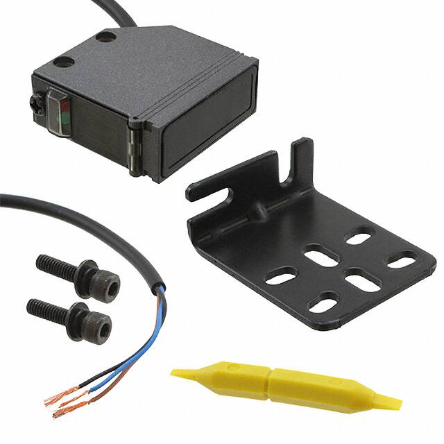
RX-LS200
FIBER
SENSORS
Related Information
■■General terms and conditions............. F-3
■■Glossary of terms........................ P.1549~
Amplifier Built-in
■■Selection guide................................P.231~
■■General precautions.................... P.1552~
LASER
SENSORS
PHOTOELECTRIC
SENSORS
MICRO
PHOTOELECTRIC
SENSORS
AREA
SENSORS
SAFETY LIGHT
CURTAINS /
SAFETY COMPONENTS
PRESSURE /
FLOW
SENSORS
INDUCTIVE
PROXIMITY
SENSORS
PARTICULAR
USE SENSORS
SENSOR
OPTIONS
SIMPLE
WIRE-SAVING
UNITS
WIRE-SAVING
SYSTEMS
MEASUREMENT
SENSORS
STATIC
CONTROL
DEVICES
LASER
MARKERS
PLC
HUMAN MACHINE
INTERFACES
ENERGY
MANAGEMENT
SOLUTIONS
FA COMPONENTS
panasonic.net/id/pidsx/global
Detection of different
colored objects at a certain distance
Hardly affected by color
Hardly affected by background
The color or size of the object does not affect its sensing
performance.
The sensor does not detect
the background beyond the
set distance since it is of
distance adjustable type.
MACHINE VISION
SYSTEMS
Robust
UV CURING
SYSTEMS
Its robust enclosure is made of die-cast zinc alloy.
Selection
Guide
Amplifier
Built-in
Power Supply
Built-in
Amplifierseparated
EX-Z
EX-10
EX-20
EX-30
EX-40
CX-440
ENVIRONMENTAL RESISTANCE
BASIC PERFORMANCE
Waterproof IP67 (IEC)
High-speed response time: 1 ms
The equipment on which the sensor is mounted can be
washed without any problem.
It can be used on a high speed assembly line.
Note: �However, take care that if it is exposed to water splashes
during operation. It may detect a water drop itself.
Insusceptible to dust
The sensing performance
is less affected by dust as
it does not depend on the
incident light intensity.
Adjustable Range Reflective Type
The sensing range for which the sensor detects an
object is determined by the incident beam angle,
regardless of the incident light intensity.
RX-LS200
Dust
Receiving element
(2-segment device)
MQ-W
RX-LS200
RX
RT-610
Receiving lens
The sensing range can be changed
according to the position of the lens.
Sensing object
EQ-30
EQ-500
Background
(specular)
However, changing the angle of the sensor
is necessary when the background object
has a specular surface.
CX-400
CY-100
PNP output
type available
Sensing object
Emitting LED
Emitting lens
Sensing range
�Adjustable Range Reflective Photoelectric Sensor
RX-LS200
APPLICATIONS
344
FIBER
SENSORS
Detecting lids of cups
Safekeeping at parking garage
LASER
SENSORS
PHOTOELECTRIC
SENSORS
MICRO
PHOTOELECTRIC
SENSORS
AREA
SENSORS
SAFETY LIGHT
CURTAINS /
SAFETY
COMPONENTS
Cut a hole on the conveyor
line so that the beam cannot
be reflected without a lid.
PRESSURE /
FLOW
SENSORS
INDUCTIVE
PROXIMITY
SENSORS
PARTICULAR
USE
SENSORS
ORDER GUIDE
Type
SENSOR
OPTIONS
Appearance
Sensing range
NPN output
50 to 200 mm
1.969 to 7.874 in
PNP output
Model No.
Output
RX-LS200
NPN open-collector transistor
RX-LS200-P
PNP open-collector transistor
SIMPLE
WIRE-SAVING
UNITS
WIRE-SAVING
SYSTEMS
MEASUREMENT
SENSORS
STATIC
CONTROL
DEVICES
LASER
MARKERS
5 m cable length type
5 m 16.404 ft cable length type (standard: 3 m 9.843 ft) is also available for NPN output type.
Model No.: RX-LS200-C5
PLC
HUMAN
MACHINE
INTERFACES
Accessory
ENERGY
MANAGEMENT
SOLUTIONS
• MS-RX-1 (Sensor mounting bracket)
FA
COMPONENTS
MACHINE
VISION
SYSTEMS
UV
CURING
SYSTEMS
Two M4 (length 16 mm 0.630 in)
hexagon-socket-head bolts are attached.
OPTIONS
Designation
Selection
Guide
Model No.
Description
Slit size
OS-RXL-2
3.0 × 24 mm
0.118 0.945 in
PT-RX500
500 mm
19.685 in
PT-RX1000
Length
OS-RXL-3
3.5 × 24 mm
0.138 0.945 in
Protective tube
• OS-RXL-□
1,000 mm
39.370 in
Amplifier
Built-in
Power Supply
Built-in
Amplifierseparated
2.5 × 24 mm
0.098 0.945 in
OS-RXL-1
Narrow-view
slit mask
Narrow-view slit mask
EX-Z
The sensing view is narrowed laterally
so that the effect of the object’s
surroundings is reduced.
CX-400
CY-100
EX-10
EX-20
Cable is protected from external forces.
It does not rust as it is made of
stainless steel.
Protective tube
EX-30
• PT-RX500
• PT-RX1000
Protective tube
EX-40
CX-440
EQ-30
EQ-500
MQ-W
RX-LS200
RX
RT-610
�345
Adjustable Range Reflective Photoelectric Sensor
SPECIFICATIONS
FIBER
SENSORS
LASER
SENSORS
PHOTOELECTRIC
SENSORS
MICRO
PHOTOELECTRIC
SENSORS
AREA
SENSORS
SAFETY LIGHT
CURTAINS /
SAFETY
COMPONENTS
PRESSURE /
FLOW
SENSORS
INDUCTIVE
PROXIMITY
SENSORS
PARTICULAR
USE
SENSORS
Item
50 to 200 mm 1.969 to 7.874 in with white non-glossy paper (50 × 50 mm 1.969 × 1.969 in)
10 % or less of operation distance with white non-glossy paper (50 × 50 mm 1.969 × 1.969 in)
Repeatability
Along sensing axis: 1 mm 0.039 in or less, Perpendicular to sensing axis: 0.5 mm 0.020 in or less
Supply voltage
12 to 24 V DC ±10 % Ripple P-P 10 % or less
Current consumption
40 mA or less
NPN open-collector transistor
• Maximum sink current: 100 mA
• Applied voltage: 30 V DC or less (between output and 0 V)
• Residual voltage: �1.5 V or less (at 100 mA sink current)
0.4 V or less (at 16 mA sink current)
Output
Utilization category
FA
COMPONENTS
MACHINE
VISION
SYSTEMS
UV
CURING
SYSTEMS
Switchable either Light-ON or Dark-ON
Short-circuit protection
–
Incorporated
Response time
1 ms or less
Operation indicator
Red LED (lights up when the output is ON)
Stability indicator
Green LED (lights up under stable light received condition or stable dark condition)
Distance adjuster
2-turn mechanical adjuster
Pollution degree
3 (Industrial environment)
Protection
IP67 (IEC)
Ambient temperature
–25 to 60 °C –13 to 140 °F (No dew condensation or icing allowed), Storage: –30 to 70 °C –22 to 158 °F
Ambient humidity
35 to 85 % RH, Storage: 35 to 85 % RH
Ambient illuminance
Incandescent light: 3,500 ℓx or less at the light-receiving face
Voltage withstandability
1,000 V AC for one min. between all supply terminals connected together and enclosure
Insulation resistance
20 MΩ, or more, with 250 V DC megger between all supply terminals connected together and enclosure
Vibration resistance
10 to 500 Hz frequency, 1.5 mm 0.059 in double amplitude (10 G max.) in X, Y and Z directions for two hours each
500 m/s2 acceleration (50 G approx.) in X, Y and Z directions three times each
Shock resistance
Emitting element
Infrared LED (peak emission wavelength: 880 nm 0.035mil, modulated)
Material
Enclosure: Die-cast zinc alloy, Indicator cover: Polyethersulphone, Lens: Polycarbonate
0.15 mm2 3-core oil, heat and cold resistant cabtyre cable, 3 m 9.843 ft long
Cable
Selection
Guide
Cable extension
Amplifier
Built-in
Weight
Power Supply
Built-in
Accessories
Amplifierseparated
PNP open-collector transistor
• Maximum source current: 100 mA
• Applied voltage: 30 V DC or less (between output and +V)
• Residual voltage: �1 V or less (at 100 mA source current)
0.4 V or less (at 16 mA source current)
DC-12 or DC-13
Output operation
Environmental resistance
ENERGY
MANAGEMENT
SOLUTIONS
RX-LS200-P
EMC Directive, RoHS Directive
Hysteresis
PLC
HUMAN
MACHINE
INTERFACES
PNP output type
RX-LS200
Model No.
Sensing range
WIRE-SAVING
SYSTEMS
LASER
MARKERS
NPN output type
CE marking directive compliance
SIMPLE
WIRE-SAVING
UNITS
STATIC
CONTROL
DEVICES
Adjustable range reflective
Type
SENSOR
OPTIONS
MEASUREMENT
SENSORS
RX-LS200
Extension up to total 100 m 328.084 ft is possible with 0.3 mm2, or more, cable.
Net weight: 85 g approx.
MS-RX-1 (Sensor mounting bracket): 1 set, Adjusting screwdriver: 1 pc.
Note: Where measurement conditions have not been specified precisely, the conditions used were an ambient temperature of +23 °C +73.4 °F.
I/O CIRCUIT AND WIRING DIAGRAMS
EX-Z
CX-400
CY-100
EX-10
EX-20
RX-LS200
I/O circuit diagram
EQ-30
(Brown) +V
Sensor circuit
CX-440
ZD
D
(Black) Output
RX-LS200
RX
RT-610
Load
100 mA max.
Tr
EQ-500
MQ-W
Wiring diagram
Color code
EX-30
EX-40
NPN output type
+
–
(Blue) 0 V
12 to 24 V DC
±10 %
Brown
Black
Users’ circuit
Symbols … D : Reverse supply polarity protection diode
ZD : Surge absorption zener diode
Tr : NPN output transistor
+
–
Blue
Internal circuit
Load
12 to 24 V DC
±10 %
�Adjustable Range Reflective Photoelectric Sensor
RX-LS200
346
I/O CIRCUIT AND WIRING DIAGRAMS
FIBER
SENSORS
RX-LS200-P
PNP output type
I/O circuit diagram
PHOTOELECTRIC
SENSORS
Wiring diagram
Color code
MICRO
PHOTOELECTRIC
SENSORS
Sensor circuit
(Brown) +V
Tr
100 mA max.
(Black) Output (Note)
ZD
D
+
–
Load
(Blue) 0 V
Brown
12 to 24 V DC
±10 %
AREA
SENSORS
+
Black
–
Load
Blue
Internal circuit
12 to 24 V DC
±10 %
Note: �The output does not incorporate a short-circuit protection circuit.
Do not connect it directly to a power supply or a capacitive load.
INDUCTIVE
PROXIMITY
SENSORS
PARTICULAR
USE
SENSORS
Symbols … D : Reverse supply polarity protection diode
ZD : Surge absorption zener diode
Tr : PNP output transistor
SENSOR
OPTIONS
SIMPLE
WIRE-SAVING
UNITS
SENSING CHARACTERISTICS (TYPICAL)
WIRE-SAVING
SYSTEMS
Sensing fields
• Setting distance: 200 mm
7.874 in (Horizontal)
• Setting distance: 200 mm
7.874 in (Vertical)
• Setting distance: 150 mm
5.906 in (Horizontal)
• Setting distance: 150 mm
5.906 in (Vertical)
200
7.874
200
7.874
200
7.874
200
7.874
0
10
0.394
Gray nonglossy paper
(Lightness: 3)
50
1.969 L
5.5 mm
0.217 in
Sensor
ℓ
Gray nonglossy paper
(Lightness: 3)
6 mm
0.236 in
Sensor
0
10
5
0
5
10
0.394
0.197
0.197
0.394
Center
Up
Down
Operating point ℓ (mm in)
5
0
5
10
0.197
0.197
0.394
Center
Left
Right
Operating point ℓ (mm in)
200
7.874
200
7.874
150
5.906
150
5.906
100
3.937
50
1.969
0
50 × 50 mm
1.969 × 1.969 in
Non-glossy
paper
L ℓ
Setting distance L (mm in)
• Setting distance: 150 mm
5.906 in with slit mask
(Vertical)
Setting distance L (mm in)
• Setting distance: 150 mm
5.906 in with slit mask
(Horizontal)
100
3.937
OS-RXL-1
OS-RXL-2
OS-RXL-3
Sensor
4
0.157
2
0
2
4
0.079
0.079
0.157
Center
Left
Right
Operating point ℓ (mm in)
0
5.5 mm 0.217 in
Sensor
100
3.937
100
3.937
50
1.969
(Lightness: 3)
2
0
2
4
0.079
0.079
0.157
Center
Left
Right
Operating point ℓ (mm in)
White non-glossy paper
Gray non-glossy paper
(Lightness: 3)
Sensing range L (mm in)
150
5.906
White non-glossy paper
100
3.937
a × a mm in
Non-glossy
paper
50
1.969
Gray non-glossy
paper
(Lightness: 3)
100 mm
3.937 in
L
Sensor
0
20
40
60
0.787
1.575
2.362
White non-glossy paper
side length a (mm in)
80
3.150
Sensor
4
2
0
2
4
0.157
0.079
0.079 0.157
Center
Up
Down
Operating point ℓ (mm in)
0
STATIC
CONTROL
DEVICES
LASER
MARKERS
PLC
HUMAN
MACHINE
INTERFACES
ENERGY
MANAGEMENT
SOLUTIONS
FA
COMPONENTS
MACHINE
VISION
SYSTEMS
UV
CURING
SYSTEMS
Selection
Guide
Amplifier
Built-in
Power Supply
Built-in
Amplifierseparated
EX-Z
Sensor
4
0.157
200 mm
7.874 in
6 mm
0.236 in
MEASUREMENT
SENSORS
6 mm
0.236 in
2
0
2
4
0.079
0.079
0.157
Center
Up
Down
Operating point ℓ (mm in)
Correlation between sensing object size and sensing range
200
7.874
ℓ
50 × 50 mm
1.969 × 1.969 in
Non-glossy
paper
ℓ
White nonglossy paper
50 × 50 mm
1.969 × 1.969 in
Non-glossy
paper
50
1.969 L
Gray non-glossy paper
0
4
0.157
Gray nonglossy paper
150 (Lightness: 3)
5.906
Common for
OS-RXL-1
OS-RXL-2
OS-RXL-3
50
1.969 L
5.5 mm 0.217 in
L ℓ
Setting distance L (mm in)
L ℓ
100
3.937
50 × 50 mm 1.969 × 1.969 in White nonNon-glossy paper
glossy paper
These curves show the characteristics with the
maximum sensing range set to 100 mm 3.937 in,
200 mm 7.874 in, each, with white non-glossy
paper (50 × 50 mm 1.969 × 1.969 in).
CX-400
CY-100
Emitted beam
EX-10
200
7.874
ø7.5 mm
ø0.295 in
150
5.906
ø6.5 mm
ø0.256 in
Distance L (mm in)
50
1.969
50 × 50 mm
1.969 × 1.969 in
Non-glossy
paper
150
5.906
Setting distance L (mm in)
100
3.937
50 × 50 mm
1.969 × 1.969 in
Non-glossy
paper
Setting distance L (mm in)
Setting distance L (mm in)
White nonglossy paper
150
5.906
150
5.906
SAFETY LIGHT
CURTAINS /
SAFETY
COMPONENTS
PRESSURE /
FLOW
SENSORS
Users’ circuit
White nonglossy paper
LASER
SENSORS
EX-20
EX-30
EX-40
CX-440
100
3.937
ø6 mm
ø0.236 in
EQ-30
50
1.969
ø5 mm
ø0.197 in
MQ-W
0
EQ-500
RX-LS200
RX
RT-610
�347
Adjustable Range Reflective Photoelectric Sensor
SENSING CHARACTERISTICS (TYPICAL)
FIBER
SENSORS
PRESSURE /
FLOW
SENSORS
INDUCTIVE
PROXIMITY
SENSORS
PARTICULAR
USE
SENSORS
SENSOR
OPTIONS
SIMPLE
WIRE-SAVING
UNITS
100
3.937
50
1.969
0
STATIC
CONTROL
DEVICES
LASER
MARKERS
5.5 mm
0.217 in
M4 (length 16 mm 0.630 in)
hexagon-socket-head bolt
FA
COMPONENTS
MACHINE
VISION
SYSTEMS
Selection
Guide
Amplifier
Built-in
Power Supply
Built-in
mm 3.937 in
50 mm 1.969 in
Mounting
• The tightening torque should be 1.17 N·m or less.
ENERGY
MANAGEMENT
SOLUTIONS
UV
CURING
SYSTEMS
···100
These bars indicate the sensing range
with respective objects when the
distance adjuster is set at the sensing
range of 200 mm 7.874 in, 100 mm
3.937 in and 50 mm 1.969 in long,
each, with white non-glossy paper.
• Never use this product as a sensing device
for personnel protection.
• In case of using sensing devices for
personnel protection, use products which
meet laws and standards, such as OSHA,
ANSI or IEC etc., for personnel protection
applicable in each region or country.
MEASUREMENT
SENSORS
HUMAN
MACHINE
INTERFACES
mm 7.874 in
PRECAUTIONS FOR PROPER USE
WIRE-SAVING
SYSTEMS
PLC
···200
···
Mirror
SAFETY LIGHT
CURTAINS /
SAFETY
COMPONENTS
150
5.906
Black rubber
AREA
SENSORS
200
7.874
Gray non-glossy paper
(Lightness: 3)
MICRO
PHOTOELECTRIC
SENSORS
Correlation between material (50 × 50 mm 1.969 × 1.969 in) and sensing range
White non-glossy paper
Plywood
Cardboard
Ceramic circuit board
Glass epoxy printed
circuit board
(Green masked surface)
PHOTOELECTRIC
SENSORS
Sensing range L (mm in)
LASER
SENSORS
RX-LS200
Beam axis
6 mm
0.236 in
Sensor mounting
bracket
MS-RX-1
(Accessory)
The sensing axis is
positioned at the
intersection of the “ ”
mark on the lens face
and the “ ” line.
• If a specular body is present in the background, wrong
operation may be caused due to a small change in the
angle of the background body. In that case, install the
sensor at an inclination and confirm the operation with
the actual sensing object.
• Do not install the sensor at a distance of less than 50 mm
1.969 in from the object because the sensing is unstable
in this range.
Wiring
• The output of RX-LS200-P does not incorporate a shortcircuit protection circuit. Do not connect it directly to a
power supply or a capacitive load.
Use conditions to comply with CE Marking
• Following work must be done in case of using this
product as a CE marking (European standard EMC
Directive) conforming product.
Ensure that the shield is connected to 0 V or the actual
ground.
• Care must be taken regarding the sensor mounting
direction with respect to the object’s direction of movement.
Correct
Refer to p.1552~ for general precautions.
Correct
Incorrect
• In case of connecting a sensor to power supply 0 V by using
a shield (piping, etc.)
Shield (piping, etc.)
Sensor
Amplifierseparated
• In case of grounding by using a shield (piping, etc.)
CX-400
EX-10
EX-20
EX-30
EX-40
CX-440
EQ-30
EQ-500
MQ-W
RX-LS200
RX
RT-610
Power supply
/
Load
OUT
Note: The shield (piping, etc.) must be insulated.
EX-Z
CY-100
+V
0V
Sensing object
Sensing object
Shield (piping, etc.)
Sensing object
Do not make the sensor
detect an object in this
direction because it may
cause unstable operation.
• When detecting a specular object (aluminum or copper
foil) or an object having a glossy surface or coating,
please take care that there are cases when the object
may not be detected due to a small change in angle,
wrinkles on the object surface, etc.
• When a specular body is present below the sensor, use
the sensor by tilting it slightly upwards to avoid wrong
operation.
Sensor
+V
Power supply
/
Load
OUT
0V
Others
• Do not use during the initial transient time (50 ms) after
the power supply is switched on.
�Adjustable Range Reflective Photoelectric Sensor
PRECAUTIONS FOR PROPER USE
Distance adjustment
RX-LS200
348
Refer to p.1552~ for general precautions.
Adjusting procedure
LASER
SENSORS
Adjusters
Pointer
It shows how much
the distance adjuster
is rotated.
Distance adjuster (2-turn)
The sensing range
increases as it is
turned clockwise.
SENS
RX-LS200
MODE
Step
Description
1
Turn the distance adjuster fully counterclockwise
to the minimum sensing range position (50 mm
1.969 in approx.).
(Do not turn excessively.)
Operation mode switch
L: Light-ON
D: Dark-ON
(Turn the switch fully.)
L
D
Operation indicator (Red)
2
Lights up when the
output is ON.
Stability indicator (Green)
Lights up under stable light received
condition or stable dark condition.
3
FIBER
SENSORS
PHOTOELECTRIC
SENSORS
Distance adjuster
MICRO
PHOTOELECTRIC
SENSORS
AREA
SENSORS
SAFETY LIGHT
CURTAINS /
SAFETY
COMPONENTS
Turn
Place an object at the required distance from
the sensor, turn the distance adjuster gradually
clockwise, and find out point “ A ” where the
sensor changes to the light received condition.
PRESSURE /
FLOW
SENSORS
INDUCTIVE
PROXIMITY
SENSORS
A
Remove the object, turn the distance adjuster
further clockwise, and find out point “ B ” where
the sensor changes to the light received
condition again with only the background.
PARTICULAR
USE
SENSORS
B
When the sensor does not go to the light
received condition even if the adjuster is fully
turned clockwise, point “ B ” is this extreme
point.
A
SENSOR
OPTIONS
SIMPLE
WIRE-SAVING
UNITS
WIRE-SAVING
SYSTEMS
4
The optimum position to stably detect objects is
the center point between “ A ” and “ B ”.
B
A
MEASUREMENT
SENSORS
Optimum position
STATIC
CONTROL
DEVICES
• Follow only steps 1 and 2 respectively. Since the sensing point
may change depending on the sensing object, be sure to check
the operation with the actual sensing object.
LASER
MARKERS
The CAD data can be downloaded from our website.
HUMAN
MACHINE
INTERFACES
DIMENSIONS (Unit: mm in)
RX-LS200 RX-LS200-P
Sensor
Operation mode switch
Distance adjuster (2-turn)
Pointer
Stability indicator (Green)
Cover-fixing screw
PT-RX500 PT-RX1000
Protective tube (Optional)
L
9
0.354
15
0.591
ø18
ø0.709 ø5
ø0.197
PLC
ENERGY
MANAGEMENT
SOLUTIONS
FA
COMPONENTS
MACHINE
VISION
SYSTEMS
Beamreceiving part
Indicator cover
(2.5)
(0.098)
14
0.551
Sensing axis
Operation indicator (Red)
35
1.378
3 0.118
2-M4 × 0.7 0.028
thru-hole threads
3.6
0.142
35
1.378
14
0.551
14
0.551
Beamemitting part
5.5
0.217
6
0.236
1.5
0.059
ø3.7ø0.146 cable, 3 m 9.843 ft long
M8 × 0.75 0.030
ø10 ø0.394
(Brass)
ø7 ø0.276 spiral tube
[Stainless steel (SUS304)]
• Length L
Model No.
Selection
Guide
Length L
PT-RX500
PT-RX1000
500 +100
19.685 +0.394
0
1,000 +100
39.370 +0.394
0
Amplifier
Built-in
Power Supply
Built-in
Amplifierseparated
Sensor mounting bracket (Accessory)
Assembly dimensions
8
16 0.315
0.630
16.5
0.650
4.4
0.173
Material: Cold rolled carbon steel (SPCC)
3 0.118
4.4 18.5
0.713 0.728
8
0.315
10
0.394
Two M4 (length 16 mm 0.630 in) hexagon-socket37 1.457
head bolts are attached.
13.5
13.5
0.531 0.531
5
15°
2 0.197
4.4
0.079
0.173
5 0.197
8.5
0.335
14
0.551
(2.5)
(0.098)
8.5
0.335
EX-10
EX-20
10
0.394
6
0.236
EX-30
EX-40
CX-440
EQ-500
Sensing axis
15°
4.4
0.173
37
1.457
35
1.378
CY-100
EQ-30
R14 R0.551
45
1.772 38
1.496
EX-Z
CX-400
Sensing axis
10
0.394
4.4
0.173
UV
CURING
SYSTEMS
Internal thread
M8 × 0.75 0.030, 4 0.157 deep
MS-RX-1
24
0.945
14 0.551
M10 × 1 0.039 thread
[Brass (C3604) (Nickel plated)]
MQ-W
45
1.772
t2
t 0.079
RX-LS200
16
0.630
16 0.630
24.5 0.965
30 1.181
RX
RT-610
�


 工商网监
湘ICP备2023018690号
工商网监
湘ICP备2023018690号
