925
FIBER
SENSORS
Thru-beam Type Ultrasonic Sensor
US-N300
Related Information
■■General terms and conditions.............. F-3
■■General precautions....................... P.1595
■■Selection guide...............................P.865~
LASER
SENSORS
PHOTOELECTRIC
SENSORS
MICRO
PHOTOELECTRIC
SENSORS
AREA
SENSORS
SAFETY LIGHT
CURTAINS /
SAFETY COMPONENTS
PRESSURE /
FLOW
SENSORS
INDUCTIVE
PROXIMITY
SENSORS
PARTICULAR
USE SENSORS
SENSOR
OPTIONS
SIMPLE
WIRE-SAVING
UNITS
WIRE-SAVING
SYSTEMS
MEASUREMENT
SENSORS
STATIC
CONTROL
DEVICES
LASER
MARKERS
PLC
HUMAN MACHINE
INTERFACES
ENERGY
MANAGEMENT
SOLUTIONS
FA COMPONENTS
panasonic.net/id/pidsx/global
Suitable for detecting transparent films�
or transparent bottles
Reliable detection of transparent objects
Only 16 mm 0.630 in thick
The sensor reliably
detects transparent films
or transparent objects.
Its 16 mm 0.630 in thick compact body allows mounting
in a narrow space.
MACHINE VISION
SYSTEMS
Simple operation mode selection
UV CURING
SYSTEMS
The operation mode can be selected either soundreceived-ON or sound-blocked-ON simply by changing
the connection of the control input wire.
Selection
Guide
Liquid Leak
Detection
Liquid Level
Detection
Water
Detection
Color Mark
Detection
Wafer
Detection
APPLICATIONS
Detecting transparent film or
transparent glass
Detecting transparent bottles
Detecting transparent and
opaque objects
Ultrasonic
Small / Slim
Object Detection
Obstacle
Detection
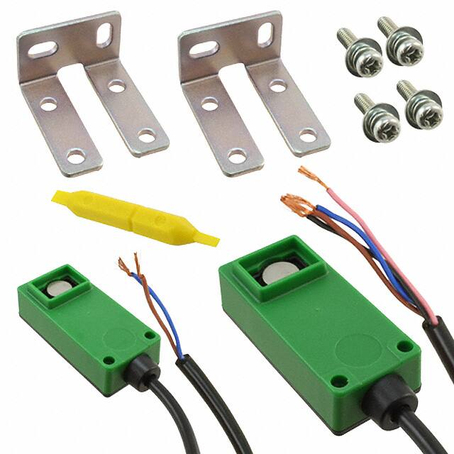
ORDER GUIDE
US-N300
Thru-beam
5 m 16.404 ft 2 m 6.562 ft
cable length cable length
Type
Appearance
Sensing range
Model No.
(Note)
Output
Accessory
・M
� S-N30
(Sensor mounting bracket)
US-N300
300
mm
�
11.811 in
NPN transistor
universal
US-N300-C5
Note: Models whose model name on the product nameplate is followed by “P” are transmitter, while those
whose model name is followed by “D” are receiver.
Two M4
(length 15 mm 0.591 in)
screws with washers
are attached.
�Thru-beam Type Ultrasonic Sensor
US-N300
SPECIFICATIONS
FIBER
SENSORS
Type
Item
926
LASER
SENSORS
Thru-beam
PHOTOELECTRIC
SENSORS
US-N300
Model No.
Sensing range
300 mm 11.811 in
Sensing object
Transparent, translucent or opaque object: 20 × 20 mm 0.787 × 0.787 in or more, Hole: 10 × 10 mm 0.394 × 0.394 in or more
Supply voltage
12 to 24 V DC ±10 % Ripple P-P 10 % or less
AREA
SENSORS
Transmitter: 35 mA or less, Receiver: 35 mA or less
SAFETY LIGHT
CURTAINS /
SAFETY
COMPONENTS
Current consumption
NPN transistor universal
• Maximum sink current: 100 mA
• Residual voltage: 1 V or less (at 100 mA sink current)
Output
Output operation
INDUCTIVE
PROXIMITY
SENSORS
Incorporated
Response time
PARTICULAR
USE
SENSORS
5 ms or less
Operation indicator
Red LED (lights up when the output is ON)
Sensitivity adjuster
Continuously variable adjuster
Transmission frequency
Environmental resistance
PRESSURE /
FLOW
SENSORS
Selectable either sound-received-ON or sound-blocked-ON by the control input
Short-circuit protection
SENSOR
OPTIONS
SIMPLE
WIRE-SAVING
UNITS
220 kHz approx.
Protection
IP62 (IEC)
0 to +50 °C +32 to +122 °F (No dew condensation), Storage: -25 to +70 °C -13 to +158 °F
Ambient temperature
Ambient humidity
35 to 85 % RH, Storage: 35 to 85 % RH
Voltage withstandability
1,500 V AC for one min. between all supply terminals connected together and enclosure
Insulation resistance
20 MΩ, or more, with 500 V DC megger between all supply terminals connected together and enclosure
Vibration resistance
10 to 55 Hz frequency, 1.5 mm 0.059 in double amplitude in X, Y and Z directions for two hours each
100 m/s2 acceleration (10 G approx.) in X, Y and Z directions three times each
Shock resistance
Material
Extension up to total 100 m 328.084 ft is possible, for both transmitter and receiver, with 0.2 mm2, or more, cable.
Weight
Transmitter: 80 g approx., Receiver: 85 g approx.
MS-N30 (Sensor mounting bracket): 1 set for transmitter and receiver, Adjusting screwdriver: 1 pc.
Accessories
Note: Where measurement conditions have not been specified precisely, the conditions used were an ambient temperature of +23 ˚C +73.4 ˚F.
I/O CIRCUIT AND WIRING DIAGRAMS
I/O circuit diagram
Sensor circuit
Tr
Color code
Load
+
(Black) Output
100 mA max.
(Blue) 0 V
(Pink) Control input
Internal circuit
ENERGY
MANAGEMENT
SOLUTIONS
FA
COMPONENTS
MACHINE
VISION
SYSTEMS
Selection
Guide
Brown
D1
ZD
LASER
MARKERS
Wiring diagram
(Brown) + V
4.7 kΩ
STATIC
CONTROL
DEVICES
UV
CURING
SYSTEMS
Color code
D2
MEASUREMENT
SENSORS
HUMAN
MACHINE
INTERFACES
0.2 mm2 4-core (transmitter: 2-core) cabtyre cable, 2 m 6.562 ft long
Cable extension
WIRE-SAVING
SYSTEMS
PLC
Enclosure: Polycarbonate
Cable
MICRO
PHOTOELECTRIC
SENSORS
-
12 to 24 V DC
±10 %
Load
Black
Liquid Leak
Detection
+
-
12 to 24 V DC
±10 %
Blue
*1
Pink
Symbols... D1: Reverse supply polarity protection diode
D2: Reverse current protection diode
ZD: Surge absorption zener diode
Tr : NPN output transistor
Water
Detection
Color Mark
Detection
*1
Wafer
Detection
Ultrasonic
Users’ circuit
Note: The transmitter has only two power supply wires (+V and 0 V).
Liquid Level
Detection
Small / Slim
Object Detection
*1
Non-voltage contact, NPN open-collector transistor or
NPN non-contact transistor
Obstacle
Detection
US-N300
or
or
• Control input
Low (-0.5 to +1.5 V, or connected to 0 V): Sound-received-ON
High (6 V to supply voltage, or open): Sound-blocked-ON
�927
Thru-beam Type Ultrasonic Sensor
SENSING CHARACTERISTICS (TYPICAL)
AREA
SENSORS
SAFETY LIGHT
CURTAINS /
SAFETY
COMPONENTS
PRESSURE /
FLOW
SENSORS
INDUCTIVE
PROXIMITY
SENSORS
PARTICULAR
USE
SENSORS
SENSOR
OPTIONS
400
15.748
300
11.811
Sensing field
400
15.748
ℓ
200
7.874
L
100
3.937
0
40
1.575
200
7.874
200
7.874
Transmitter
Receiver
Transmitter
100
3.937
20
0
20
40
0.787
0.787
1.575
Left
Center
Right
Operating point ℓ (mm in)
Receiver 50 × 50 mm 1.969 × 1.969 in
Sound insulation board
ℓ
300
11.811 300
11.811
300
11.811
100
3.937
θL
0
40
Receiver
20
0
20
Left
Center
Right
Operating angle θ (°)
L
Transmitter
40
0
20
0.787
10
0
10
20
0.394
0.394
0.787
Left
Center
Right
Operating point ℓ (mm in)
PRECAUTIONS FOR PROPER USE
SIMPLE
WIRE-SAVING
UNITS
• Never use this product as a sensing device
for personnel protection.
• In case of using sensing devices for
personnel protection, use products which
meet laws and standards, such as OSHA,
ANSI or IEC etc., for personnel protection
applicable in each region or country.
WIRE-SAVING
SYSTEMS
MEASUREMENT
SENSORS
STATIC
CONTROL
DEVICES
LASER
MARKERS
Angular deviation
400
15.748
Setting distance L (mm in)
MICRO
PHOTOELECTRIC
SENSORS
Parallel deviation
Setting distance L (mm in)
PHOTOELECTRIC
SENSORS
Setting distance L (mm in)
FIBER
SENSORS
LASER
SENSORS
US-N300
Refer to p.1595 for general precautions.
Influence of background objects
• If sensor heads are installed as shown in the figure
below, the operation may become unstable by the
reflected sound wave.
An object, hard and
plain like a glass plate,
reflects the sound
wave.
Background
Mounting
• The tightening torque should be 0.49 N·m or less.
PLC
Transmitter
HUMAN
MACHINE
INTERFACES
ENERGY
MANAGEMENT
SOLUTIONS
Receiver
Placed perpendicular
to the sensing axis.
Sensing object
The receiver should be placed away from the object and at
an angle to it as shown below.
FA
COMPONENTS
MACHINE
VISION
SYSTEMS
M4 (length
15 mm 0.591 in)
screws with
washers
UV
CURING
SYSTEMS
Receiver
Sensor mounting
bracket
MS-N30
(Accessory)
10° approx.
Transmitter
Object
Selection
Guide
Liquid Leak
Detection
Liquid Level
Detection
Water
Detection
Color Mark
Detection
Wafer
Detection
Ultrasonic
Small / Slim
Object Detection
Obstacle
Detection
US-N300
Mutual interference
Sensitivity adjustment
• Normally, use the sensor at the maximum sensitivity.
However, if the sensing is not proper due to surrounding
objects (reflection from surrounding objects, etc.), adjust
the sensitivity.
• When two or more sensors are mounted close together,
the sensors may not enter the “sound-blocked state” due
to mutual interference.
Parallel mounting
Influence of surrounding objects
Influence of an object parallel to the sensing axis
• If there is a wall or a curtain near the sensing axis, the
sound reflection may cause the operation to be unstable.
Face-to-face mounting
①
Receiver Transmitter
Transmitter
Transmitter
Receiver
Transmitter
Receiver
Keep a distance of 10 mm 0.394 in or more
Sensing axis
Receiver
②
Transmitter
Keep a distance of 20 mm 0.787 in or more
Wall or curtain
Receiver
Keep a distance of
100 mm 3.937 in or more
Transmitter
Receiver Receiver Transmitter Transmitter
Back-to-back mounting is possible.
�Thru-beam Type Ultrasonic Sensor
PRECAUTIONS FOR PROPER USE
Traveling speed and minimum sensing object width
• Minimum sensing object width is 20 × 20 mm 0.787 ×
0.787 in in the stationary condition.
The minimum sensing width of a traveling object is
related to the traveling speed and the sensor response
time by the following formula.
W = VT + A (m)
W : Minimum sensing object width (m)
V : Traveling speed of the object (m/sec.)
T : Sensor response time = 0.005 (sec.)
A : M
� inimum sensing object width in the stationary condition
= 0.02 0.066 (m ft)
Example: �If V = 10 m 32.808 ft /sec.
W=
� 10 32.808 × 0.005 0.016 + 0.02 0.066
= 0.07 m 0.230 ft
= 70 mm 2.756 in
US-N300
928
Refer to p.1595 for general precautions.
FIBER
SENSORS
LASER
SENSORS
Others
• Do not use during the initial transient time (50 ms) after the
power supply is switched on.
• The ultrasonic sound propagates through the air.
If the sensor is used at a place where air blows or the
temperature suddenly changes (near a door, an air
conditioner, etc.) the operation may become unstable.
Avoid using US-N300 at such places.
• Take care that the sensor may malfunction due to an
intense extraneous sound, such as, metal impact sound.
• Do not expose the transmitting element or the receiving
element to moisture or dust. It may affect the sensing
operation.
PHOTOELECTRIC
SENSORS
MICRO
PHOTOELECTRIC
SENSORS
AREA
SENSORS
SAFETY LIGHT
CURTAINS /
SAFETY
COMPONENTS
PRESSURE /
FLOW
SENSORS
INDUCTIVE
PROXIMITY
SENSORS
PARTICULAR
USE
SENSORS
SENSOR
OPTIONS
DIMENSIONS (Unit: mm in)
The CAD data can be downloaded from our website.
US-N300
Sensor
SIMPLE
WIRE-SAVING
UNITS
WIRE-SAVING
SYSTEMS
MEASUREMENT
SENSORS
12.1 0.476
12.6 0.496
STATIC
CONTROL
DEVICES
8.3 7.4
Sensitivity adjuster (receiver only)
0.327 0.291
Operation indicator (Red) (Receiver only)
20
0.787
(2)
28
16
(0.079)
1.102
0.630
LASER
MARKERS
PLC
13 0.512
HUMAN
MACHINE
INTERFACES
60
2.63243
1.693
ENERGY
MANAGEMENT
SOLUTIONS
FA
COMPONENTS
7.5 0.295
2-M4 × 0.7 0.028
thru-hole threads
4
0.157
MACHINE
VISION
SYSTEMS
ø4.8 ø0.189 cable, 2 m 6.562 ft long
ø13
ø0.512
20
0.787
UV
CURING
SYSTEMS
MS-N30
Sensor mounting bracket (Accessory)
Assembly dimensions
12 4
0.472 0.157
4.3
0.169
19
0.748
4.3
0.169
37
32
1.457 1.260
20
0.787
30
1.181
20
0.787
4
0.157
t2
t 0.079
20
0.787
4.3
0.169
Selection
Guide
Liquid Leak
Detection
4
32 39
0.157 1.260 1.535
4.3
0.169
Liquid Level
Detection
Water
Detection
(2)
(0.079)
Color Mark
Detection
28
Wafer
Detection
Ultrasonic
8 0.315
Small / Slim
Object Detection
88
3.465 75
2.953
20 0.787
12 0.472
Mounting drawing
with the receiver
4
0.157
4-ø4.3
ø0.169 holes
Material: Cold rolled carbon steel (SPCC)
Two M4 (length 15 mm 0.591 in) screws with washers are attached.
32 28
1.260 1.102 12
0.472
5
0.197
Obstacle
Detection
20
0.787
30
1.181
4-ø4.3 ø0.169
holes
5
0.197
t2
t 0.079
19
0.748
35
1.378
39
1.535
US-N300
�
很抱歉,暂时无法提供与“US-N300-P”相匹配的价格&库存,您可以联系我们找货
免费人工找货