NHD-1.8-128160EF-CTXI#-FT 数据手册
NHD-1.8-128160EF-CTXI#-FT
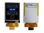
TFT (Thin-Film Transistor) Liquid Crystal Display Module
NHD1.8128160EFCTXI#FT-
Newhaven Display
1.8” Diagonal
128 x 160 Pixels (Portrait Mode)
Model
Built-in Controller
White LED Backlight
TFT
6:00 Optimal View, Wide Temperature
RoHS Compliant
FFC ZIF Connection Style
4-wire Resistive Touch Panel
Newhaven Display International, Inc.
2661 Galvin Ct.
Elgin IL, 60124
Ph: 847-844-8795
Fax: 847-844-8796
www.newhavendisplay.com
nhtech@newhavendisplay.com
nhsales@newhavendisplay.com
�Document Revision History
Revision
0
1
2
Date
9/11/2013
8/12/16
9/26/18
3
4
5
3/21/19
1/13/21
3/8/21
Description
Initial Release
Datasheet Reformat
Mechanical Drawing, Backlight Characteristics & Supply
Current Updated
Driver Updated from ILI9163C to ILI9163V
Updated 2D Mechanical Drawing & Quality Information
2D Mechanical Drawing Redesign; Updated Footnote for
Backlight Drive Conditions, Typical Backlight Voltage, Optical
Characteristics & Quality Information
Functions and Features
•
•
•
•
•
•
128 x 160 pixels (portrait mode)
LED backlight
2.8V power supply
8-bit Parallel interface
Built-in ILI9163V controller
4-wire Resistive touch panel
[2]
Changed by
AK
SB
SB
SB
AS
AS
�3
Mechanical Drawing
Green Tear tape
XR
Front
YD
0.5±0.1
F
Notes:
1. Display Size:
2. Op�mal View:
3. Display Mode:
4. Driver IC:
5. Supply Voltage:
6. Backlight:
7. Luminance:
8. Touch Panel:
1
8.4±0.2
P=0.5
11.5±0.1
0.3±0.05
8.95±0.2
3
Pin No.
1
2
3
4
5
6
7
8
9
10
11
12
13
14
15
16
17
18
19
20
21
22
23
24
.3
R0
1.0max
single area
Stiffener
12.5±0.1
1.77” TFT
6:00
Transmissive /Normal White / An�-Glare
ILI9163V
2.8 V
White LED / 3.2 V / 30 mA (Typ)
280 cd/m² (Typ)
4-Wire Resis�ve
2
TFT Pinout:
component area
24
1
B
tape
Stiffener
CONTACT SIDE
WWYY
Date code on the
back of FPC
W=0.35
30.19±0.2
E
550R6
3±0.5
17.63±0.3
2.36±0.3
D.S.T
T=0.10MM
YU XL YD XR
D
D.S.T
T=0.10MM
White silk on FPC
YU XL YD XR
DATE
3±0.3
37.04/TP(V,A)
36.04/TP(A,A)
A.A 35.04
22±0.5
tape
8
(16.5)
10±0.5
YU
128(RGB)X160 DOTS
7
REVISION
NEWHAVEN DISPLAY
WWYY
NHD-1.8-128160EF-CTXI#-FT_rev14
3.45±0.2
Except the double side tape
4.5±0.5
(2.27)
(2.77)
(3.27)
1.9±0.4
37.79±0.2/TOP-POL
BL 46.75±0.2
46.35±0.2/TP
C
0.2±0.2
1.73±0.4
(2.33)
(2.83)
(3.34)
A.A 28.03
XL
6
A
31.23±0.2/TOP-POL
30.03/TP(V,A)
29.03TP/(A,A)
RGB
5
SYMBOL
BL 34.7±0.2
34.3±0.2/TP
B
4
Back
A
2
NEWHAVEN DISPLAY
WWYY
NHD-1.8-128160EF-CTXI#-FT_rev14
1
Symbol
GND
IOVDD
VDD
/CS
/RST
D/C
/WR
/RD
DB0
DB1
DB2
DB3
DB4
DB5
DB6
DB7
LED-A
LED-K1
LED-K2
GND
YU
XL
YD
XR
C
D
E
Standard Tolerance:
(Unless otherwise specified)
Linear:
±0.3mm
Unless otherwise specified:
• Dimensions are in Millimeters
• Third Angle Projection
Drawing/Part Number:
NHD-1.8-128160EF-CTXI#-FT
Drawn By:
Drawn Date:
A. Shah
3/5/2021
Approved By:
Approved Date:
Do Not Scale Drawing
A. Shah
3/5/2021
Revision:
14
Size:
A3
Scale:
NS
Sheet 1 of 1
This drawing is solely the property of Newhaven Display International, Inc.
The information it contains is not to be disclosed, reproduced or copied in
whole or part without written approval from Newhaven Display.
4
5
6
7
8
F
�Pin Description and Wiring Diagram
Pin No.
1
2
3
4
5
6
7
8
9
10
11
12
13
14
15
16
17
18
19
20
21
22
23
24
Symbol
GND
IOVDD
VDD
/CS
/RST
D/C
/WR
/RD
DB0
DB1
DB2
DB3
DB4
DB5
DB6
DB7
LED-A
LED-K1
LED-K2
GND
YU
XL
YD
XR
External Connection
Power Supply
Power Supply
Power Supply
MPU
MPU
MPU
MPU
MPU
MPU
MPU
MPU
MPU
MPU
MPU
MPU
MPU
Power Supply
Power Supply
Power Supply
Power Supply
Touch Controller
Touch Controller
Touch Controller
Touch Controller
Function Description
Ground
Supply Voltage for Logic (2.8V) – Can be tied to VDD
Power Supply for LCD (2.8V)
Active LOW Chip Select signal
Active LOW Reset signal
Data / Command selection: ‘1’ = Data; ‘0’ = Command
Active LOW Write signal
Active LOW Read signal
8-bit bi-directional data bus
Backlight Anode (30mA @ 3.2V)
Backlight Cathode (Ground)
Backlight Cathode (Ground)
Ground
Touch Panel Up
Touch Panel Left
Touch Panel Down
Touch Panel Right
LCD connector: 24pin 0.5mm FFC connector. Molex P/N: 52435-2471
[4]
�Electrical Characteristics
Item
Operating Temperature Range
Storage Temperature Range
Supply Voltage for Logic
Supply Voltage for LCD
Supply Current
“H” Level input
“L” Level input
“H” Level output
“L” Level output
Backlight Supply Current
Backlight Supply Voltage
Backlight Lifetime*
Symbol
TOP
TST
IOVDD
VDD
IDD
VIH
VOH
VIL
VOH
Condition
Absolute Max
Absolute Max
VDD = 2.8V
-
Min.
-20
-30
1.65
2.5
1
0.7*IOVDD
GND
0.8*IOVDD
GND
Typ.
2.8
2.8
3
-
Max.
+70
+80
3.3
3.3
5
IOVDD
0.3*IOVDD
IOVDD
0.2*IOVDD
Unit
°C
°C
V
V
mA
V
V
V
V
ILED
VLED
ILED = 30 mA
ILED = 30 mA
TOP = 25°C
2.8
20,000
30
3.2
50,000
40
3.3
-
mA
V
Hrs.
-
*Backlight lifetime is rated as Hours until half-brightness, under normal operating conditions. The LED of the backlight is driven by current drain; drive voltage is for
reference only. Drive voltage must be selected to ensure backlight current drain is below MAX level stated
Optical Characteristics
Optimal
Viewing
Angle
Item
Top
Bottom
Left
Right
Contrast Ratio
Luminance
Response Time (Rise + Fall)
Symbol
ϕY+
ϕYθXθ+
CR
LV
TR+TF
Condition
Min.
400
220
-
CR ≥ 10
ILED = 30mA
TOP = 25°C
Typ.
40
60
60
60
500
280
8
Max.
16
Touch Panel Characteristics
Item
Linearity
Circuit Resistance – X-Axis
Circuit Resistance – Y-Axis
Insulation Resistance
Operating Voltage
Chattering
Activation Force
Pen Writing Durability
Pitting Durability
Surface Hardness
Min.
-1.5
150
250
20
20
100,000
1,000,000
3
Typ.
5
-
Max.
1.5
550
800
10
10
80
-
Unit
%
Ω
Ω
MΩ
V
ms
g
Characters
Touches
H
Controller Information
Built-in ILI9163V controller.
Please download specification at http://www.newhavendisplay.com/app_notes/ILI9163.pdf
[5]
Unit
⁰
⁰
⁰
⁰
cd/m2
ms
�Table of Commands
[6]
�For Command Descriptions, please see: http://www.newhavendisplay.com/app_notes/ILI9163.pdf
[7]
�Timing Characteristics
Parallel 8-bit Bus
[8]
�Reset Timing
[9]
�Example Program Code
void TFT_18E_Init(void)
{
GPIO_ResetBits(GPIOC, CS1);
GPIO_SetBits(GPIOC, nRD);
GPIO_ResetBits(GPIOC, nWR);
GPIO_WriteBit(GPIOC, RES, Bit_RESET);
delay(5);
TFT_delay(10);
GPIO_WriteBit(GPIOC, RES, Bit_SET);
delay(100);
TFT_delay(10);
TFT_18E_Write_Command(0x11);
TFT_delay(100);
TFT_18E_Write_Command(0x26);TFT_18E_Write_Data(0x04);
TFT_18E_Write_Command(0xF2);TFT_18E_Write_Data(0x00);
TFT_18E_Write_Command(0xB1);TFT_18E_Write_Data(0x0A);TFT_18E_Write_Data(0x14);
TFT_18E_Write_Command(0xC0);TFT_18E_Write_Data(0x0A);TFT_18E_Write_Data(0x00);
TFT_18E_Write_Command(0xC1);TFT_18E_Write_Data(0x02);
TFT_18E_Write_Command(0xC5);TFT_18E_Write_Data(0x2F);TFT_18E_Write_Data(0x3E);
TFT_18E_Write_Command(0xC7);TFT_18E_Write_Data(0x40);
TFT_18E_Write_Command(0x2A);
TFT_18E_Write_Data(0x00);
TFT_18E_Write_Data(0x00);
TFT_18E_Write_Data(0x00);
TFT_18E_Write_Data(0x7F);
TFT_18E_Write_Command(0x2B);
TFT_18E_Write_Data(0x00);
TFT_18E_Write_Data(0x00);
TFT_18E_Write_Data(0x00);
TFT_18E_Write_Data(0x9F);
TFT_18E_Write_Command(0x36);TFT_18E_Write_Data(0x48);
TFT_18E_Write_Command(0x3A);TFT_18E_Write_Data(0xC5);
TFT_18E_Write_Command(0x29);
TFT_18E_Write_Command(0x2C);
}
/***************************************************************************************/
void TFT_18E_Write_Command(unsigned char command)
{
GPIO_ResetBits(GPIOC, RS);
GPIO_Write(GPIOB, command);
GPIO_ResetBits(GPIOC, nWR);
GPIO_SetBits(GPIOC, nWR);
}
/***************************************************************************************/
void TFT_18E_Write_Data(unsigned char data1)
{
GPIO_SetBits(GPIOC, RS);
GPIO_Write(GPIOB, data1);
GPIO_ResetBits(GPIOC, nWR);
GPIO_SetBits(GPIOC, nWR);
}
/***************************************************************************************/
[10]
�Quality Information
Test Item
Content of Test
High Temperature storage
Endurance test applying the high storage
temperature for a long time.
Endurance test applying the low storage
temperature for a long time.
Endurance test applying the electric stress
(voltage & current) and the high thermal
stress for a long time.
Endurance test applying the electric stress
(voltage & current) and the low thermal
stress for a long time.
Endurance test applying the electric stress
(voltage & current) and the high thermal
with high humidity stress for a long time.
Endurance test applying the electric stress
(voltage & current) during a cycle of low
and high thermal stress.
Endurance test applying vibration to
simulate transportation and use.
Endurance test applying electric static
discharge.
Low Temperature storage
High Temperature
Operation
Low Temperature
Operation
High Temperature /
Humidity Storage
Thermal Shock resistance
Vibration test
Static electricity test
Test Condition
2
-30⁰C , 96hrs
1,2
+70⁰C , 96hrs
2
-20⁰C , 96hrs
1,2
+50⁰C , 90% RH , 96hrs
1,2
-20℃ 30 min ~ +70℃ 30 min,
20 cycles
10-50Hz , 5G amplitude.
30min in each of 3 directions X, Y, Z
Air: ±8kV 150pF/330Ω, 5 Times
Contact: ±4kV 150pF/330Ω, 5 Times
Note 1: No condensation to be observed.
Note 2: Conducted after 4 hours of storage at 25⁰C, 0%RH.
Note 3: Test performed on product itself, not inside a container.
Precautions for using LCDs/LCMs
See Precautions at www.newhavendisplay.com/specs/precautions.pdf
Warranty Information
See Terms & Conditions at http://www.newhavendisplay.com/index.php?main_page=terms
[11]
Note
+80⁰C , 96hrs
3
�


 工商网监
湘ICP备2023018690号
工商网监
湘ICP备2023018690号