NHD-2.4-240320CF-CTXI#-F 数据手册
NHD-2.4-240320CF-CTXI#-F
TFT (Thin-Film Transistor) Liquid Crystal Display Module
NHD2.4240320CFCTXI#F-
Newhaven Display
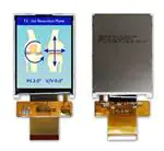
2.4” Diagonal
240 x 320 Pixels (Portrait Mode)
Model
Built-in Controller
White LED Backlight
TFT
6:00 Optimal View, Wide Temperature
RoHS Compliant
FFC ZIF Connection Style
Newhaven Display International, Inc.
2661 Galvin Ct.
Elgin IL, 60124
Ph: 847-844-8795
Fax: 847-844-8796
www.newhavendisplay.com
nhtech@newhavendisplay.com
nhsales@newhavendisplay.com
�Document Revision History
Revision
0
1
2
Date
12/9/14
3/10/15
10/1/15
3
4
5
6
7
8
9
10
11
3/18/16
4/7/16
6/3/16
2/7/17
5/9/18
8/23/19
2/25/20
3/3/20
3/31/21
Description
Initial Release
Luminance rating updated
Mechanical Drawing, Supply Voltage and Supply Current
Updated
Datasheet Reformat, Added Backlight Lifetime
Viewing Angle Clarification
Updated Brightness Rating
Bezel Redesign & Supply Current Updated
Updated for new controller
Interface Information Updated (8080-II)
Updated Electrical Characteristics
Backlight Design Updated, Updated Electrical Characteristics
Updated Alignment Tab Length + Tolerance on 2D
Mechanical Drawing
Functions and Features
•
•
•
•
•
•
•
•
240 x 320 pixels
LED backlight
3.3V power supply
8-bit or 16-bit Parallel MPU interface (8080-II Series)
FFC ZIF I/O connection
Built-in ST7789Vi controller
262K colors
Touch Panel available
[2]
Changed by
AK
AK
SB
SB
SB
SB
SB
TM
SM
TM
SB
AS
�1
2
3
4
5
6
SYMBOL
7
8
REVISION
DATE
A
A
B
B
C
C
D
D
E
E
F
1.
2.
3.
4.
5.
6.
7.
8.
Display Size:
Op�mal View:
Display Mode:
Driver IC:
Supply Voltage:
Backlight:
Brightness:
Film:
1
2.4” TFT
6:00
Transmissive / Normally White / An�-Glare
ST7789Vi: 8-16Bit Parallel Interface
3.3V
White LED/ 80 mA (Typ) / 3.1V
350cd/m² (Typ)
3M Brightness Enhancement
2
3
STANDARD TOLERANCE:
(UNLESS OTHERWISE SPECIFIED)
LINEAR: ±0.3mm
5
6
1C
NHD-2.4-240320CF-CTXI#-F
UNLESS OTHERWISE SPECIFIED:
DRAWN BY:
- DIMENSIONS ARE IN MILLIMETERS
DRAWN DATE:
- THIRD ANGLE PROJECTION
4
REVISION:
DRAWING/PART NUMBER:
A. Shah
3/31/21
APPROVED BY:
SIZE:
A3
A. Shah
SCALE:
APPROVED DATE:
DO NOT SCALE DRAWING
NS
3/31/21
SHEET 1 OF 1
THIS DRAWING IS SOLELY THE PROPERTY OF NEWHAVEN DISPLAY INTERNATIONAL, INC.
THE INFORMATION IT CONTAINS IS NOT TO BE DISCLOSED, REPRODUCED OR COPIED IN
WHOLE OR PART WITHOUT WRITTEN APPROVAL FROM NEWHAVEN DISPLAY.
7
8
F
�Pin Description
Pin No.
1
2
3
4
5
6
7
8
9
10
11
12
13
14
15
16
17
18
19
20
21
22
23
24
25
26
27
28
29
30
31
32
33
34
35
36
37
38
39
40
Symbol
GND
NC
NC
NC
NC
NC
VDD
IOVDD
NC
/CS
D/C
/WR
/RD
DB0
DB1
DB2
DB3
DB4
DB5
DB6
DB7
DB8
DB9
DB10
DB11
DB12
DB13
DB14
DB15
/RES
IM0
NC
GND
LED-K1
LED-K2
LED-K3
LED-K4
LED-A
GND
NC
External Connection
Power Supply
Power Supply
Power Supply
MPU
MPU
MPU
MPU
MPU
MPU
MPU
MPU
MPU
MPU
MPU
MPU
MPU
MPU
MPU
MPU
MPU
MPU
MPU
MPU
MPU
MPU
Power Supply
Power Supply
Power Supply
Power Supply
Power Supply
Power Supply
Power Supply
-
Function Description
Ground
No Connect
No Connect
No Connect
No Connect
No Connect
Supply Voltage for LCD (3.3)
Supply Voltage for Logic (1.8V, can tie to VDD)
No Connect
Active LOW Chip Select signal (can tie to GND)
Data / Command selection: ‘1’ = Data; ‘0’ = Command
Active LOW Write signal
Active LOW Read signal
Bi-directional data bus
8-bit: use DB8-DB15
16-bit: use DB0-DB15
Active LOW Reset signal
IM0=0: 16-bit (8080-II)
No Connect
Ground
Backlight Cathode (Ground)
Backlight Cathode (Ground)
Backlight Cathode (Ground)
Backlight Cathode (Ground)
Backlight Anode (3.1V)
Ground
No Connect
Recommended LCD connector: 40-pin, 0.5mm pitch FFC connector
[4]
IM0=1: 8-bit (8080-II)
Molex P/N: 54132-4062 or similar
�Wiring Diagram
[5]
�Electrical Characteristics
Item
Operating Temperature Range
Storage Temperature Range
Supply Voltage for LCD
Supply Voltage for Logic
Supply Current
“H” Level input
“L” Level input
“H” Level output
“L” Level output
Backlight Supply Current
Backlight Supply Voltage
Backlight Lifetime*
Symbol
TOP
TST
VDD
IOVDD
IDD
VIH
VIL
VOH
VOL
Condition
Absolute Max
Absolute Max
VDD=3.3V
-
Min.
-20
-30
2.4
1.65
2
0.7 * VDD
VSS
0.8 * VDD
VSS
Typ.
3.3
1.8
6
-
Max.
+70
+80
3.6
3.6
12
VDD
0.3 * VDD
VDD
0.2 * VDD
Unit
⁰C
⁰C
V
V
mA
V
V
V
V
ILED
VLED
-
ILED = 80 mA
TOP = 25° C
2.8
20,000
80
3.1
50,000
100
3.5
-
mA
V
Hrs.
*Backlight lifetime is rated as Hours until half-brightness, under normal operating conditions. The LED of the backlight is driven by current drain; drive voltage is for
reference only. Drive voltage must be selected to ensure backlight current drain is below MAX level stated
Optical Characteristics
Optimal
Viewing
Angles
Item
Top
Bottom
Left
Right
Contrast Ratio
Luminance
Response Time
Rise
Fall
Red
Green
Chromaticity
Blue
White
Symbol
ϕY+
ϕYθXθX+
CR
LV
TR
TF
XR
YR
XG
YG
XB
YB
XW
YW
Condition
CR ≥ 10
ILED = 80 mA
TOP = 25° C
TOP = 25° C
θX = 0°
ϕY = 0°
Min.
150
252
0.531
0.314
0.291
0.524
0.112
0.051
0.251
0.271
Typ.
50
55
55
55
200
350
4
12
0.561
0.334
0.319
0.564
0.142
0.081
0.291
0.311
Max.
448
8
24
0.591
0.374
0.351
0.614
0.162
0.112
0.331
0.351
Controller Information
Built-in ST7789Vi controller.
Please download specification at
https://www.newhavendisplay.com/resources_dataFiles/datasheets/LCDs/ST7789Vi.pdf
Table of Commands
Please download specification at
https://www.newhavendisplay.com/resources_dataFiles/datasheets/LCDs/ST7789Vi.pdf
[6]
Unit
⁰
⁰
⁰
⁰
cd/m2
ms
ms
-
�Timing Characteristics
Parallel 16/8-bit Interface Timing Characteristics (8080-II system)
[7]
�Reset Timing
Power ON/OFF Sequence
[8]
�Example Initialization Code
/*******************************************************************************/
void TFT_24_7789_Write_Command(unsigned int command)
{
GPIO_ResetBits(GPIOC, CS1);
GPIO_ResetBits(GPIOC, RS);
GPIO_SetBits(GPIOC, nRD);
GPIO_ResetBits(GPIOC, nWR);
GPIO_Write(GPIOB, command);
TFT_delay(10);
GPIO_SetBits(GPIOC, nWR);
TFT_delay(1);
}
/*******************************************************************************/
void TFT_24_7789_Write_Data(unsigned int data1)
{
GPIO_Write(GPIOB, data1);
GPIO_SetBits(GPIOC, RS);
GPIO_ResetBits(GPIOC, nWR);
TFT_delay(1);
GPIO_SetBits(GPIOC, nWR);
}
/*******************************************************************************/
void TFT_24_7789_Init(void)
{
int n;
GPIO_ResetBits(GPIOC, CS1);
GPIO_SetBits(GPIOC, nRD);
GPIO_ResetBits(GPIOC, nWR);
GPIO_WriteBit(GPIOC, RES, Bit_RESET);
TFT_delay(100);
GPIO_WriteBit(GPIOC, RES, Bit_SET);
TFT_delay(100);
TFT_24_7789_Write_Command(0x0011);//exit SLEEP mode
TFT_delay(100);
TFT_24_7789_Write_Command(0x0036);
TFT_24_7789_Write_Data(0x0080);//MADCTL: memory data access control
TFT_24_7789_Write_Command(0x003A);
TFT_24_7789_Write_Data(0x0066);//COLMOD: Interface Pixel format
TFT_24_7789_Write_Command(0x00B2);
TFT_24_7789_Write_Data(0x000C);
TFT_24_7789_Write_Data(0x0C);
TFT_24_7789_Write_Data(0x00);
TFT_24_7789_Write_Data(0x33);
TFT_24_7789_Write_Data(0x33);//PORCTRK: Porch setting
TFT_24_7789_Write_Command(0x00B7);
TFT_24_7789_Write_Data(0x0035);//GCTRL: Gate Control
TFT_24_7789_Write_Command(0x00BB);
TFT_24_7789_Write_Data(0x002B);//VCOMS: VCOM setting
TFT_24_7789_Write_Command(0x00C0);
TFT_24_7789_Write_Data(0x002C);//LCMCTRL: LCM Control
TFT_24_7789_Write_Command(0x00C2);
TFT_24_7789_Write_Data(0x0001);
TFT_24_7789_Write_Data(0xFF);//VDVVRHEN: VDV and VRH Command Enable
TFT_24_7789_Write_Command(0x00C3);
TFT_24_7789_Write_Data(0x0011);//VRHS: VRH Set
TFT_24_7789_Write_Command(0x00C4);
TFT_24_7789_Write_Data(0x0020);//VDVS: VDV Set
[9]
�TFT_24_7789_Write_Command(0x00C6);
TFT_24_7789_Write_Data(0x000F);//FRCTRL2: Frame Rate control in normal mode
TFT_24_7789_Write_Command(0x00D0);
TFT_24_7789_Write_Data(0x00A4);
TFT_24_7789_Write_Data(0xA1);//PWCTRL1: Power Control 1
TFT_24_7789_Write_Command(0x00E0);
TFT_24_7789_Write_Data(0x00D0);
TFT_24_7789_Write_Data(0x0000);
TFT_24_7789_Write_Data(0x0005);
TFT_24_7789_Write_Data(0x000E);
TFT_24_7789_Write_Data(0x0015);
TFT_24_7789_Write_Data(0x000D);
TFT_24_7789_Write_Data(0x0037);
TFT_24_7789_Write_Data(0x0043);
TFT_24_7789_Write_Data(0x0047);
TFT_24_7789_Write_Data(0x0009);
TFT_24_7789_Write_Data(0x0015);
TFT_24_7789_Write_Data(0x0012);
TFT_24_7789_Write_Data(0x0016);
TFT_24_7789_Write_Data(0x0019);//PVGAMCTRL: Positive Voltage Gamma control
TFT_24_7789_Write_Command(0x00E1);
TFT_24_7789_Write_Data(0x00D0);
TFT_24_7789_Write_Data(0x0000);
TFT_24_7789_Write_Data(0x0005);
TFT_24_7789_Write_Data(0x000D);
TFT_24_7789_Write_Data(0x000C);
TFT_24_7789_Write_Data(0x0006);
TFT_24_7789_Write_Data(0x002D);
TFT_24_7789_Write_Data(0x0044);
TFT_24_7789_Write_Data(0x0040);
TFT_24_7789_Write_Data(0x000E);
TFT_24_7789_Write_Data(0x001C);
TFT_24_7789_Write_Data(0x0018);
TFT_24_7789_Write_Data(0x0016);
TFT_24_7789_Write_Data(0x0019);//NVGAMCTRL: Negative Voltage Gamma control
TFT_24_7789_Write_Command(0x002A);
TFT_24_7789_Write_Data(0x0000);
TFT_24_7789_Write_Data(0x0000);
TFT_24_7789_Write_Data(0x0000);
TFT_24_7789_Write_Data(0x00EF);//X address set
TFT_24_7789_Write_Command(0x002B);
TFT_24_7789_Write_Data(0x0000);
TFT_24_7789_Write_Data(0x0000);
TFT_24_7789_Write_Data(0x0001);
TFT_24_7789_Write_Data(0x003F);//Y address set
TFT_delay(10);
}
/*******************************************************************************/
[10]
�Quality Information
Test Item
Content of Test
Test Condition
Note
High Temperature
Storage
Endurance test applying the high storage
temperature for a long time.
+80⁰C, 96hrs
2
Low Temperature
Storage
High Temperature
Operation
Endurance test applying the low storage
temperature for a long time.
Endurance test applying the electric stress
(voltage & current) and the high thermal
stress for a long time.
-30⁰C, 96hrs
1,2
+70⁰C, 96hrs
2
Low Temperature
Operation
Endurance test applying the electric stress
(voltage & current) and the low thermal
stress for a long time.
-20⁰C, 96hrs
1,2
High Temperature /
Humidity Operation
Endurance test applying the electric stress
(voltage & current) and the high thermal with
high humidity stress for a long time.
+40⁰C, 90-95% RH, 96hrs
1,2
Thermal Shock resistance
Endurance test applying the electric stress
(voltage & current) during a cycle of low and
high thermal stress.
-20⁰C,30min -> 25⁰C,5min ->
70⁰C,30min -> 25⁰C,5min = 1
cycle. 10 cycles
Vibration test
Endurance test applying vibration to simulate
transportation and use.
Endurance test applying electric static
discharge.
10Hz-55Hz, 1.5mm amplitude.
2hrs in each of 3 directions X,Y,Z
VS=8KV, RS=330kΩ, CS=150pF
Ten times
Static electricity test
Note 1: No condensation to be observed.
Note 2: Conducted after 4 hours of storage at 25⁰C, 0%RH.
Note 3: Test performed on product itself, not inside a container.
Precautions for using LCDs/LCMs
See Precautions at www.newhavendisplay.com/specs/precautions.pdf
Warranty Information
See Terms & Conditions at http://www.newhavendisplay.com/index.php?main_page=terms
[11]
3
�


 工商网监
湘ICP备2023018690号
工商网监
湘ICP备2023018690号