NHD-2.4-240320SF-CTXI#-1 数据手册
N
NHD‐‐2.4‐‐240320SSF‐C
CTXI##‐1
TFTT (Thin‐‐Film Trransisto
or) Liquid Crysttal Disp
play Mo
odule
NHD‐‐
2.4‐
2403
320‐
SF‐
C‐
T‐
X‐
I‐
#‐
1‐
Newhaven Display
2.4” Diagonal
24
40 x 320 Pixels (Portrait M
Mode)
Model
M
Built‐in Contro
oller
White LED Bac
W
cklight
TFT
12
2:00 Optimal View, Wide TTemperature
RoHS Compliant
ILLI9341 Contro
oller
Newh
haven Disp
play Intern
national, In
nc.
2511 Techno
ology Drive, SSuite 101
Elggin IL, 60124
Ph: 8
847‐844‐8795
5
Fax: 8847‐844‐87966
www.new
whavendisplayy.com
nhtech
h@newhaven
ndisplay.com
nhsaales@newhavvendisplay.co
om
�Document Revision History
Revision
0
1
2
3
Date
9/17/2010
5/9/2012
6/25/2012
12/11/2012
4
7/15/2013
5
10/10/2013
6
4/21/2014
Description
Initial Release
Timing characteristics updated
Electrical & Optical characteristics updated
Added wiring diagram. Updated mechanical drawing &
electrical characteristics.
Controller changed to ILI9341
Mechanical Drawing, Pin Description, Wiring Diagram,
Electrical/Optical Characteristics, Example Code updated
Changed optimal viewing direction in datasheet
Functions and Features
240 x 320 pixels
LED backlight
2.8V power supply
8‐bit or 16‐bit Parallel MPU interface
Hot‐Bar Solder I/O connection
Built‐in ILI9341 controller
262K colors
Touch Panel available
[2]
Changed by
MC
AK
TJ
JN
ML
ML
ML
�L
A
I
Mechanical Drawing
1
2
3
4
A
Rev
D
1
6
Date
GND
YD
XL
YU
XR
LCD_ID
VDD
IOVDD
FMARK
/CS
D/C
/WR
/RD
DB0
DB1
DB2
DB3
DB4
DB5
DB6
DB7
DB8
DB9
DB10
DB11
DB12
DB13
DB14
DB15
/RES
IM0
NC
GND
LED-K1
LED-K2
LED-K3
LED-K4
LED-A
GND
T
N
F
N
O
C
Description
E
D
I
B
C
5
B
C
D
Date
10/10/13
2
A
3
4
Gen. Tolerance
Unit
±0.3mm
mm
5
Model:
NHD-2.4-240320SF-CTXI#-1
6
The drawing contained herein is the exclusive property of Newhaven Display International, Inc. and shall not be copied, reproduced, and/or disclosed in any format without permission.
[3]
�Pin Descripttion
Pin N
No. Symbol
1
2
3
4
5
6
7
8
9
10
11
12
13
14
15
16
17
18
19
20
21
22
23
24
25
26
27
28
29
30
31
32
33
34
35
36
37
38
39
GND
D
YD
XL
YU
XR
LCD_ID
VDD
IOVDD
D
FMAR
RK
/CS
D/C
/WR
R
/RD
DB0
DB1
DB2
DB3
DB4
DB5
DB6
DB7
DB8
DB9
DB10
0
DB11
1
DB12
2
DB13
3
DB14
4
DB15
5
/RESS
IM0
NC
GND
D
LED‐K
K1
LED‐K
K2
LED‐K
K3
LED‐K
K4
LED‐A
A
GND
D
External
Connection
Pow
wer Supply
‐
‐
‐
‐
MPU/NC
M
Pow
wer Supply
Pow
wer Supply
MPU/NC
M
MPU
MPU
MPU
MPU
MPU
MPU
MPU
MPU
MPU
MPU
MPU
MPU
MPU
MPU
MPU
MPU
MPU
MPU
MPU
MPU
MPU
MPU
‐
Pow
wer Supply
Pow
wer Supply
Pow
wer Supply
Pow
wer Supply
Pow
wer Supply
Pow
wer Supply
Pow
wer Supply
Function Desccription
Ground
No Connect
No Connect
No Connect
No Connect
LCD ID pin (No
o Connect)
Supply Voltage for LCD (2.8V
V)
Supply Voltage for Logic (2.88V)
Used when wrriting RAM datta in sync with frame (No Con
nnect)
Active LOW Ch
hip Select sign al (can tie to G
GND)
Data / Commaand selection: ‘1’ = Data ; ‘0’ = Command
Active LOW W
Write signal
Active LOW Re
ead signal
Bi‐directional data bus
8‐DB15
8‐bit: use DB8
16‐bit: use DB
B0‐DB15
Active LOW Re
eset signal
IM0=0: 16‐bit i80 IM
M0=1: 8‐bit i800
No Connect
Ground
Backlight Cath
hode (Ground)
Backlight Cath
hode (Ground)
Backlight Cath
hode (Ground)
Backlight Cath
hode (Ground)
Backlight Anode (3.2V)
Ground
CB. 1mm pitcch.
LCD cconnector: Hot‐bar solderr directly to PC
[4]
�Wirring Diagram
[5]
�Electrical Characteristics
Item
Operating Temperature Range
Storage Temperature Range
Supply Voltage for LCD
Supply Voltage for Logic
Supply Current
“H” Level input
“L” Level input
“H” Level output
“L” Level output
Backlight Supply Voltage
Backlight Supply Current
Symbol
Top
Tst
VDD
IOVDD
IDD
Vih
Vil
Voh
Vol
Vled
Iled
Condition
Absolute Max
Absolute Max
‐
‐
VDD=2.8V
‐
‐
‐
‐
Min.
‐20
‐30
2.5
1.65
‐
0.8*VDD
GND
0.8*VDD
GND
Typ.
‐
‐
2.8
2.8
7
‐
‐
‐
‐
3.2
60
Max.
+70
+80
3.3
3.3
9
VDD
0.2*VDD
VDD
0.2*VDD
3.4
‐
Unit
⁰C
⁰C
V
V
mA
V
V
V
V
V
mA
‐
Vled=3.2V
2.9
‐
Symbol
‐
‐
‐
‐
Cr
Lv
Tr+Tf
Condition
Min.
‐
‐
‐
‐
400
‐
‐
Typ.
60
70
70
70
500
310
20
Max.
‐
‐
‐
‐
‐
‐
30
Unit
⁰
⁰
⁰
⁰
‐
cd/m2
ms
Optical Characteristics
Item
Viewing Angle – Top
Viewing Angle – Bottom
Viewing Angle – Left
Viewing Angle – Right
Contrast Ratio
Luminance
Response Time (rise + fall)
Cr ≥ 10
‐
‐
‐
Viewing angles based on 6:00 gray scale inversion
Controller Information
Built‐in ILI9341 controller.
Please download specification at http://www.newhavendisplay.com/app_notes/ILI9341.pdf
Table of Commands
Please download specification at http://www.newhavendisplay.com/app_notes/ILI9341.pdf
[6]
�Tim
ming Charracteristiccs
Paraallel 18/16//9/8‐bit Intterface Timing Charactteristics (80080‐II systeem)
[7]
�
[8]
�Example Recommended Initialization Code
/**************************************************************/
void TFT_24S_Write_Command(int command)
{
GPIO_ResetBits(GPIOC, DC);
GPIO_Write(GPIOB, command);
GPIO_ResetBits(GPIOC, nWR);
GPIO_SetBits(GPIOC, nWR);
}
void TFT_24S_Write_Data(int data)
{
GPIO_SetBits(GPIOC, DC);
GPIO_Write(GPIOB, data);
GPIO_ResetBits(GPIOC, nWR);
GPIO_SetBits(GPIOC, nWR);
}
/**************************************************************/
void init()
{
GPIO_ResetBits(GPIOC, CS);
GPIO_SetBits(GPIOC, nRD);
GPIO_ResetBits(GPIOC, nWR);
GPIO_WriteBit(GPIOC, RES, Bit_RESET);
delay(120);
GPIO_WriteBit(GPIOC, RES, Bit_SET);
delay(120);
TFT_24S_Write_Command(0x0028);
//display OFF
TFT_24S_Write_Command(0x0011);
//exit SLEEP mode
TFT_24S_Write_Data(0x0000);
TFT_24S_Write_Command(0x00CB);
//Power Control A
TFT_24S_Write_Data(0x0039);
//always 0x39
TFT_24S_Write_Data(0x002C);
//always 0x2C
TFT_24S_Write_Data(0x0000);
//always 0x00
TFT_24S_Write_Data(0x0034);
//Vcore = 1.6V
TFT_24S_Write_Data(0x0002);
//DDVDH = 5.6V
TFT_24S_Write_Command(0x00CF);
//Power Control B
TFT_24S_Write_Data(0x0000);
//always 0x00
TFT_24S_Write_Data(0x0081);
//PCEQ off
TFT_24S_Write_Data(0x0030);
//ESD protection
TFT_24S_Write_Command(0x00E8);
//Driver timing control A
TFT_24S_Write_Data(0x0085);
//non‐overlap
TFT_24S_Write_Data(0x0001);
//EQ timing
//Pre‐charge timing
TFT_24S_Write_Data(0x0079);
TFT_24S_Write_Command(0x00EA);
//Driver timing control B
TFT_24S_Write_Data(0x0000);
//Gate driver timing
TFT_24S_Write_Data(0x0000);
//always 0x00
[9]
�TFT_24S_Write_Command(0x00ED);
TFT_24S_Write_Data(0x0064);
TFT_24S_Write_Data(0x0003);
TFT_24S_Write_Data(0x0012);
TFT_24S_Write_Data(0x0081);
//Power‐On sequence control
//soft start
//power on sequence
//power on sequence
//DDVDH enhance on
TFT_24S_Write_Command(0x00F7);
TFT_24S_Write_Data(0x0020);
TFT_24S_Write_Command(0x00C0);
TFT_24S_Write_Data(0x0026);
TFT_24S_Write_Data(0x0004);
//Pump ratio control
//DDVDH=2xVCI
//power control 1
TFT_24S_Write_Command(0x00C1);
TFT_24S_Write_Data(0x0011);
//power control 2
TFT_24S_Write_Command(0x00C5);
TFT_24S_Write_Data(0x0035);
TFT_24S_Write_Data(0x003E);
//VCOM control 1
TFT_24S_Write_Command(0x00C7);
TFT_24S_Write_Data(0x00BE);
//VCOM control 2
TFT_24S_Write_Command(0x0036);
TFT_24S_Write_Data(0x0088);
//memory access control = BGR
TFT_24S_Write_Command(0x00B1);
TFT_24S_Write_Data(0x0000);
TFT_24S_Write_Data(0x0010);
//frame rate control
TFT_24S_Write_Command(0x00B6);
TFT_24S_Write_Data(0x000A);
TFT_24S_Write_Data(0x00A2);
//display function control
TFT_24S_Write_Command(0x003A);
TFT_24S_Write_Data(0x0055);
//pixel format = 16 bit per pixel
TFT_24S_Write_Command(0x00F2);
TFT_24S_Write_Data(0x0002);
//3G Gamma control
//off
TFT_24S_Write_Command(0x0026);
TFT_24S_Write_Data(0x0001);
//Gamma curve 3
TFT_24S_Write_Command(0x002A);
TFT_24S_Write_Data(0x0000);
TFT_24S_Write_Data(0x0000);
TFT_24S_Write_Data(0x0000);
TFT_24S_Write_Data(0x00EF);
//column address set
//second parameter for ILI9340 (ignored by ILI9341)
//start 0x0000
//end 0x00EF
TFT_24S_Write_Command(0x002B);
TFT_24S_Write_Data(0x0000);
TFT_24S_Write_Data(0x0000);
TFT_24S_Write_Data(0x0001);
TFT_24S_Write_Data(0x003F);
//page address set
//start 0x0000
//end 0x013F
}
[10]
�Quality Information
Test Item
Content of Test
Test Condition
Note
High Temperature
Storage
Endurance test applying the high storage
temperature for a long time.
+80⁰C, 96hrs
2
Low Temperature
Storage
High Temperature
Operation
Endurance test applying the low storage
temperature for a long time.
Endurance test applying the electric stress
(voltage & current) and the high thermal
stress for a long time.
‐30⁰C, 96hrs
1,2
+70⁰C, 96hrs
2
Low Temperature
Operation
Endurance test applying the electric stress
(voltage & current) and the low thermal
stress for a long time.
‐20⁰C, 96hrs
1,2
High Temperature /
Humidity Operation
Endurance test applying the electric stress
(voltage & current) and the high thermal with
high humidity stress for a long time.
+50⁰C, 90% RH, 96hrs
1,2
Thermal Shock resistance
Endurance test applying the electric stress
(voltage & current) during a cycle of low and
high thermal stress.
‐10⁰C,30min ‐> 25⁰C,5min ‐>
60⁰C,30min = 1 cycle
100 cycles
Vibration test
Endurance test applying vibration to simulate
transportation and use.
10Hz‐55Hz‐10Hz , 1.5mm
amplitude.
60 mins in each of 3 directions
X,Y,Z
Static electricity test
Endurance test applying electric static
discharge.
VS=8KV, RS=330kΩ, CS=150pF
Ten times
Note 1: No condensation to be observed.
Note 2: Conducted after 4 hours of storage at 25⁰C, 0%RH.
Note 3: Test performed on product itself, not inside a container.
Precautions for using LCDs/LCMs
See Precautions at www.newhavendisplay.com/specs/precautions.pdf
Warranty Information
See Terms & Conditions at http://www.newhavendisplay.com/index.php?main_page=terms
[11]
3
�
NHD-2.4-240320SF-CTXI#-1 价格&库存
很抱歉,暂时无法提供与“NHD-2.4-240320SF-CTXI#-1”相匹配的价格&库存,您可以联系我们找货
免费人工找货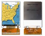


 工商网监
湘ICP备2023018690号
工商网监
湘ICP备2023018690号