NHD-320240WG-BXSFH-VZ 数据手册
NHD‐320240WG‐BxSFH‐VZ#
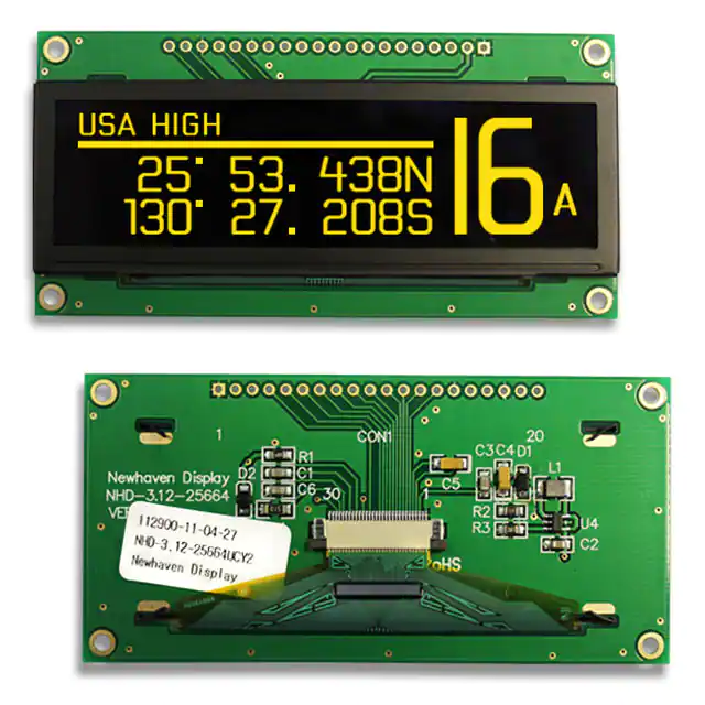
Graphic Liquid Crystal Display Module
NHD‐ 320240‐ WG‐ Bx‐ S‐ F‐ H‐ VZ#‐ Newhaven Display 320 x 240 pixels Display Type: Graphic Model Bright White LED Backlight FSTN (+) Transflective, 6:00 view, Wide Temperature (‐20°C ~+70°C) Built‐in Negative Voltage RoHS Compliant
Newhaven Display International, Inc.
2511 Technology Drive, Suite 101 Elgin IL, 60124 Ph: 847‐844‐8795 Fax: 847‐844‐8796
www.newhavendisplay.com nhsales@newhavendisplay.com nhtech@newhavendisplay.com [1]
�
Document Revision History
Revision 0 1 2 • • • • Date 6/7/2007 3/12/2010 9/2/2010 Description Initial Release User guide reformat Mechanical drawing update Changed by ‐ MC MP
Functions and Features
320 x 240 pixels Built‐in S1D13700 Controller +5.0V power supply RoHS Compliant
[2]
�Mechanical Drawing
160.0 0.5 4.0
11.31
25.0 28.41
152.0 122.0(VA) 115.18(AA)
13.0MAX 6.5 1.0
101.0
320*240 Dots 190.0 5.0
1.0 (PCB) LED B/L
4-3.5PTH 4-PAD
The non-specified tolerance of dimension is
0.3mm.
1 2 3 4 5 6 7 8 9 10 11 12 13 14 15 16 17 18 19 20
VSS VDD Vo A0 R/W E DB0 DB1 DB2 DB3 DB4 DB5 DB6 DB7 /CS /RST Vee NC NC WAIT
4.0
2.15
8.5
109.0 0.5
86.38(AA)
104.7 92.0(VA)
RD W R A0 DB0~DB7 CS RES SEL1 *
SED13700 Controller
CL1 M FLM
0.36 0.34
LED B/L drive directly fromA and K.
R
Driver Driver
Com1~80 Com81~160
0.36 0.34
MPU
Power ON Reset
320X240 DOT
VR 10K~20K
Bias and Power Circuit
Vdd Vo
DOT SIZE SCALE 10/1
A K
B/L LCM
Com161~240 Seg1~80 Seg81~160 Seg161~240 Seg241~320
Driver
Driver
Driver
Driver
Driver
-25V
Vee FGND
External contrast adjustment.
N.V. Generator Frame PAD
CL2 DB0~DB3
Newhaven Display
NHD-320240WG-BxSFH-VZ#
*:6800 family or 8080family interface selectable.
� Pin Description and Wiring Diagram
Pin No. Symbol 1 2 3 4 5 6 7‐14 15 16 17 18 19 20 VSS VDD V0 A0 R/W E DB0‐DB7 /CS /RST VEE NC NC WAIT External Connection Power Supply Power Supply Adj Power Supply MPU MPU MPU MPU MPU MPU Power Supply ‐ ‐ MPU Function Description Ground Power supply for logic (+5.0V) Power supply for contrast (approx. ‐18.8V) Register select signal. A0=0: Command, A0=1: Data Read/Write select signal, R/W=1: Read R/W: =0: Write Operation enable signal. Falling edge triggered. Bi‐directional three‐state data bus lines. Active LOW chip select Active LOW reset signal Negative voltage output (‐25V) No Connect No Connect Check busy
Recommended LCD connector: 1.0mm pitch, 20‐pos FFC connector Backlight connector: JST p/n: XHP‐3 Mates with: JST p/n: B 3B‐XH‐A
[4]
� Electrical Characteristics
Item Operating Temperature Range Storage Temperature Range Supply Voltage Supply Current Supply for LCD (contrast) “H” Level input “L” Level input “H” Level output “L” Level output Backlight Supply Voltage Backlight Supply Current Backlight Lifetime Symbol Top Tst VDD IDD VDD‐VLCD VIH VIL VOH VOL VLED ILED Condition Absolute Max Absolute Max Ta=25°C, VDD=5.0V Ta=25°C ‐ ‐ ‐ Min. ‐20 ‐30 4.75 65.0 22.0 0.5VDD 0 ‐0.4VDD ‐ 3.4 120 ‐ Typ. ‐ ‐ 5.0 75.0 23.8 ‐ ‐ ‐ ‐ 3.5 160 50,000 Max. +70 +80 5.25 85.0 26.1 VDD 0.2VDD ‐ 0.4 3.6 180 ‐ Unit ⁰C ⁰C V mA V V V V V V mA Hrs
VLED=3.5V ILED=160mA
Optical Characteristics
Item Viewing Angle ‐ Vertical Viewing Angle ‐ Horizontal Contrast Ratio Response Time (rise) Response Time (fall) Symbol AV AH Cr Tr Tf Condition Cr ≥ 3 Cr ≥ 3 ‐ ‐ Min. ‐20 ‐30 ‐ ‐ ‐ Typ. ‐ ‐ 3 200 150 Max. 40 30 ‐ 300 200 Unit ⁰ ⁰ ‐ ms ms
Controller Information
Built‐in S1D13700. Download specification at http://www.newhavendisplay.com/app_notes/S1D13700.pdf
[5]
� Table of Commands
[6]
�[7]
� Timing Characteristics
[8]
� Example Initialization Program:
//------------------------------------------------------------------------------Sub Writecom Set P3.0 'A0 = H = Write command P1 = A 'move data to P1 Reset P3.1 'chip select Reset P3.7 'R/W Set P3.4 'E Reset P3.4 'E Set P3.7 'R/W Set P3.1 'CS End Sub Sub Writedata Reset P3.0 'A0 = L = Write data P1 = A Reset P3.1 Reset P3.7 Set P3.4 Reset P3.4 Set P3.7 Set P3.1 End Sub //------------------------------------------------------------------------------Sub Init Set P3.2 'SEL=1 = Motorola 6800 write interface Reset P3.6 'RESET Waitms 10 'wait Set P3.6 'RESET done Waitms 100 'wait A = &H40 'system set command
[9]
�Call Writecom A = &H30 Call Writedata A = &H87 Call Writedata A = &H07 Call Writedata A = &H27 Call Writedata A = &H50 Call Writedata A = &HEF Call Writedata A = &H28 Call Writedata A = &H00 Call Writedata A = &H44 Call Writecom A = &H00 Call Writedata A = &H00 Call Writedata A = &HEF Call Writedata A = &HB0 Call Writedata A = &H04 Call Writedata A = &HEF Call Writedata A = &H00 Call Writedata A = &H00 Call Writedata A = &H00 Call Writedata A = &H00 Call Writedata A = &H5A Call Writecom A = &H00 Call Writedata A = &H5B Call Writecom A = &H00 Call Writedata A = &H5D Call Writecom A = &H04 Call Writedata A = &H86 Call Writedata A = &H4C Call Writecom Call Clr
'set parameters 'horizontal character size=8 'vertical character size=8 'display addresses per line 'total address range per line '240 display lines 'virtual address1 'virtual address2 'scroll 'start address1 'start address2 '240 lines '2nd screen start1 '2nd screen start2 '2nd screen 240 lines '3rd screen address1 '3rd screen address2 '4th screen address1 '4th screen address2 'hdot scr 'horizontal pixel shift=0 'overlay 'OR 'cursor form '5 pixels 'by 7 pixels 'cursor direction = right
'clear the screen
A = &H59 'disp on/off Call Writecom A = &H14 'on Call Writedata End Sub //-------------------------------------------------------------------------------
[10]
�Quality Information
Test Item
High Temperature storage Low Temperature storage High Temperature Operation Low Temperature Operation High Temperature / Humidity Operation Thermal Shock resistance
Content of Test
Endurance test applying the high storage temperature for a long time. Endurance test applying the low storage temperature for a long time. Endurance test applying the electric stress (voltage & current) and the high thermal stress for a long time. Endurance test applying the electric stress (voltage & current) and the low thermal stress for a long time. Endurance test applying the electric stress (voltage & current) and the high thermal with high humidity stress for a long time. Endurance test applying the electric stress (voltage & current) during a cycle of low and high thermal stress. Endurance test applying vibration to simulate transportation and use.
Test Condition
+80⁰C , 200hrs ‐30⁰C , 200hrs +70⁰C 200hrs
Note
2 1,2 2
‐20⁰C , 200hrs
1,2
+60⁰C , 90% RH , 96hrs
1,2
Vibration test
Static electricity test
Endurance test applying electric static discharge.
‐20⁰C,30min ‐> 25⁰C,5min ‐> 70⁰C,30min = 1 cycle 10 cycles 10‐55Hz , 15mm amplitude. 60 sec in each of 3 directions X,Y,Z For 15 minutes VS=800V, RS=1.5kΩ, CS=100pF One time
3
Note 1: No condensation to be observed. Note 2: Conducted after 4 hours of storage at 25⁰C, 0%RH. Note 3: Test performed on product itself, not inside a container.
Precautions for using LCDs/LCMs
See Precautions at www.newhavendisplay.com/specs/precautions.pdf
Warranty Information and Terms & Conditions
http://www.newhavendisplay.com/index.php?main_page=terms
[11]
�
NHD-320240WG-BXSFH-VZ 价格&库存
很抱歉,暂时无法提供与“NHD-320240WG-BXSFH-VZ”相匹配的价格&库存,您可以联系我们找货
免费人工找货


 工商网监
湘ICP备2023018690号
工商网监
湘ICP备2023018690号
