NHD-7.0-800480WF-CTXI#-T 数据手册
NHD-7.0-800480WF-CTXI#-T
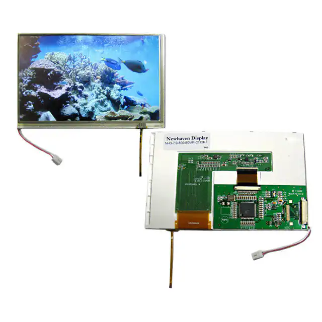
TFT (Thin-Film-Transistor) Color Liquid Crystal Display Module
NHD7.0800480WFCTXI#T-
Newhaven Display
7.0” Diagonal
800xRGBx480 pixels
Model
Built-in Controller
White LED backlight
TFT
6:00 view, Wide Temp
RoHS Compliant
Touch Panel
Newhaven Display International, Inc.
2511 Technology Drive, Suite 101
Elgin IL, 60124
Ph: 847-844-8795
Fax: 847-844-8796
www.newhavendisplay.com
nhtech@newhavendisplay.com
nhsales@newhavendisplay.com
�Document Revision History
Revision
Date
Description
Changed by
0
1
2
3
4
5
6
8/31/2010
10/5/2010
2/8/2011
2/23/2011
10/7/2011
1/6/2012
8/7/2013
Initial Release
Mechanical Drawing updated
Initialization code added
Grammar/symbols updated
Backlight and Touch Panel pin descriptions added
Pixel data format updated
Updated Functions and Features, Mechanical Drawing,
Electrical and Optical Characteristics.
MC
BE
AK
BE
AK
AK
JN
Functions and Features
•
•
•
•
•
800xRGBx480 resolution
LED backlight
8-bit MCU interface
262,144 colors
SSD1963 8-bit controller
[2]
�Mechanical Drawing
[3]
�[4]
�CON2 LCD Pin Description
Pin No.
1
2
3
4
5
Symbol
GND
VDD
NC
D/C#
WR#
Connection
Power Supply
Power Supply
MPU
MPU
Function Description
Ground
Power supply for logic (+3.3V)
No Connect
Register Select signal: 1=Data, 0=Command
Active LOW Write signal (8080 mode)
Read/Write signal (6800 mode)
Active LOW Read signal (8080 mode)
Edge trigger Enable signal (6800 mode)
6
RD#
MPU
7-14
15
16
17
18
19
20
DB0~DB7
CS#
NC
NC
RST#
NC
NC
MPU
8-bit bi-directional data bus
MPU
MPU
-
Active LOW Chip Select signal
No Connect
No Connect
Active LOW Reset signal
No Connect
No Connect
LCD connector: 1.0mm pitch,20-Conductor FFC, top contact
Recommended connection: 1.0mm pitch, 20-conductor FFC cable
CON1 TFT Pin-Out (before controller board):
Pin No.
1
2
3
4-7
8
9
10-12
13-15
16
17-19
20
21-23
24
25-27
28
29-31
32
33-35
36-37
38
39-40
Symbol
GND
GND
NC
VDD
NC
DE
GND
B5-B3
GND
B2-B0
GND
G5-G3
GND
G2-G0
GND
R5-R3
GND
R2-R0
GND
DCLK
GND
Connection
Power Supply
Power Supply
Power Supply
MPU
Power Supply
MPU
Power Supply
MPU
Power Supply
MPU
Power Supply
MPU
Power Supply
MPU
Power Supply
MPU
Power Supply
MPU
Power Supply
Function Description
Power Ground
Power Ground
No connect
Power Supply (+3.3V)
No connect
Data Enable
Power Ground
Blue B5 (MSB) to B3
Power Ground
Blue B2 – B0(LSB)
Power Ground
Green B5 (MSB) to B3
Power Ground
Green B2 – B0(LSB)
Power Ground
Red B5 (MSB) to B3
Power Ground
Red B2 – B0(LSB)
Power Ground
Clock (Falling edge triggered)
Power Ground
LCD connector: 0.5mm pitch,40-Conductor FFC, Bottom contact
Recommended connection: 0.5mm pitch, 40-conductor FFC cable
Backlight Pin-Out:
Pin No.
1
2
Symbol
VDD
GND
Connection
Power Supply
Power Supply
Function Description
Power Supply (+9.9V)
Power Ground
Backlight connector: JST p/n: BHSR-02VS-1
Recommended mating connector: JST p/n: SM 02B-BHSS-1
[5]
�Touch Panel Pin-Out:
Pin No.
1
2
3
4
Symbol
XYX+
Y+
Connection
Touch Panel
Touch Panel
Touch Panel
Touch Panel
Function Description
Touch Panel – RIGHT
Touch Panel – BOTTOM
Touch Panel – LEFT
Touch Panel – TOP
Touch Panel Characteristics
Item
Linearity
Circuit Resistance – X-Axis
Circuit Resistance – Y-Axis
Insulation Resistance
Operating Voltage
Chattering
Transmittance
Activation Force
Pen Writing Durability
Pitting Durability
Surface Hardness
Haze
Min.
450
100
10
82
50
100,000
1,000,000
3
-
Typ.
800
350
7
Max.
1.5
1300
800
5
10
200
-
[6]
Unit
%
Ω
Ω
MΩ
V
ms
%
g
Characters
Touches
H
%
�Electrical Characteristics
Item
Operating Temperature Range
Storage Temperature Range
Supply Voltage
Supply Current
“H” Level input
“L” Level input
Backlight Supply Voltage
Backlight Supply Current
Backlight Lifetime
Symbol
Top
Tst
VDD
IDD
Vih
Vil
VLED
ILED
-
Condition
Absolute Max
Absolute Max
o
VDD=3.3V 25 C
VLED=9.9V
Until half-brightness
Min.
-20
-30
3.0
0.8V*DD
-
Typ.
3.3
200
-
Max.
+70
+80
3.6
260
VDD+ 0.5
0.2*VDD
Unit
⁰C
⁰C
V
mA
V
V
140
10,000
9.9
160
20,000
180
-
V
mA
Hrs.
Optical Characteristics
Item
Viewing Angle – Top
Viewing Angle – Bottom
Viewing Angle – Left
Viewing Angle – Right
Contrast Ratio
Luminance
Response Time (rise)
Response Time (fall)
Symbol
Condition
Cr ≥10
Cr
YL
Tr
Tf
-
Min.
250
300
-
Typ.
50
70
70
70
400
350
5
11
Max.
10
16
Unit
⁰
⁰
⁰
⁰
2
cd/m
ms
ms
Controller Information
Built-in SSD1963 controller.
Please download specification at http://www.newhavendisplay.com/app_notes/SSD1963.pdf
[7]
�Parallel Interface:
The SSD1963 controller supports both 8080 mode and 6800 mode.
See the SSD1963 datasheet for detailed timing diagrams.
Command Instructions:
See the SSD1963 datasheet for the Instruction Table and Command Descriptions.
Pixel Data Format:
[8]
�Example Initialization Code
/*******************************************************************************
* Function Name : UILCD_Init
* Description : Initializes LCD.
* Input
: None
* Output
: None
* Return
: None
*******************************************************************************/
void TFT_7_Init(void)
{
GPIO_ResetBits(GPIOC, CS1);
GPIO_SetBits(GPIOC, nRD);
GPIO_ResetBits(GPIOC, nWR);
GPIO_WriteBit(GPIOC, RES, Bit_RESET);
TFT_delay(5);
GPIO_WriteBit(GPIOC, RES, Bit_SET);
TFT_delay(100);
TFT_7_Write_Command(0x01); //Software Reset
TFT_7_Write_Command(0x01);
TFT_7_Write_Command(0x01);
TFT_delay(10);
TFT_7_Command_Write(0xe0,0x01); //START PLL
TFT_7_Command_Write(0xe0,0x03); //LOCK PLL
TFT_7_Write_Command(0xb0);
//SET LCD MODE SET TFT 18Bits MODE
GPIO_SetBits(GPIOC, RS);
TFT_7_Write_Data(0x08);
//SET TFT MODE & hsync+Vsync+DEN MODE
TFT_7_Write_Data(0x80);
//SET TFT MODE & hsync+Vsync+DEN MODE
TFT_7_Write_Data(0x03);
//SET horizontal size=800-1 HightByte
TFT_7_Write_Data(0x1f);
//SET horizontal size=800-1 LowByte
TFT_7_Write_Data(0x01);
//SET vertical size=480-1 HightByte
TFT_7_Write_Data(0xdf);
//SET vertical size=480-1 LowByte
TFT_7_Write_Data(0x00);
//SET even/odd line RGB seq.=RGB
TFT_7_Command_Write(0xf0,0x00); //SET pixel data I/F format=8bit
TFT_7_Command_Write(0x36,0x09); //SET address mode=flip vertical, BGR
TFT_7_Command_Write(0x3a,0x60); // SET R G B format = 6 6 6
TFT_7_Write_Command(0xe2);
//SET PLL freq=113.33MHz
GPIO_SetBits(GPIOC, RS);
TFT_7_Write_Data(0x22);
TFT_7_Write_Data(0x03);
TFT_7_Write_Data(0x04);
TFT_7_Write_Command(0xe6);
//SET PCLK freq=33.26MHz
GPIO_SetBits(GPIOC, RS);
TFT_7_Write_Data(0x02);
TFT_7_Write_Data(0xff);
TFT_7_Write_Data(0xff);
TFT_7_Write_Command(0xb4);
//SET HBP,
GPIO_SetBits(GPIOC, RS);
TFT_7_Write_Data(0x03);
//SET HSYNC Total
TFT_7_Write_Data(0xef);
TFT_7_Write_Data(0x00);
//SET HBP
TFT_7_Write_Data(0xa3);
TFT_7_Write_Data(0x07);
//SET VBP
TFT_7_Write_Data(0x00);
//SET Hsync pulse start position
TFT_7_Write_Data(0x00);
[9]
�TFT_7_Write_Data(0x00);
TFT_7_Write_Command(0xb6);
GPIO_SetBits(GPIOC, RS);
TFT_7_Write_Data(0x01);
TFT_7_Write_Data(0xef);
TFT_7_Write_Data(0x00);
TFT_7_Write_Data(0x04);
TFT_7_Write_Data(0x01);
TFT_7_Write_Data(0x00);
TFT_7_Write_Data(0x00);
TFT_7_Write_Command(0x2a);
GPIO_SetBits(GPIOC, RS);
TFT_7_Write_Data(0x00);
TFT_7_Write_Data(0x00);
TFT_7_Write_Data(0x03);
TFT_7_Write_Data(0x1f);
TFT_7_Write_Command(0x2b);
GPIO_SetBits(GPIOC, RS);
TFT_7_Write_Data(0x00);
TFT_7_Write_Data(0x00);
TFT_7_Write_Data(0x01);
TFT_7_Write_Data(0xdf);
/*TFT_7_Write_Command(0x33);
GPIO_SetBits(GPIOC, RS);
TFT_7_Write_Data(0x00);
TFT_7_Write_Data(0x00);
TFT_7_Write_Data(0x01);
TFT_7_Write_Data(0xdf);
TFT_7_Write_Data(0x00);
TFT_7_Write_Data(0x00);
TFT_7_Write_Command(0x28);
}
//SET Hsync pulse subpixel start position
//SET VBP,
//SET Vsync total = 496
//SET VBP=4
//SET Vsync pulse 2=1+1
//SET Vsync pulse start position
//SET column address
//SET start column address=0
//SET end column address=799
//SET page address
//SET start page address=0
//SET end page address=479
//SET scroll area
//SET top fixed area=0
//SET vertical scrolling area=479
//SET bottom fixed area=0
//SET display off */
void TFT_7_Write_Command(unsigned char command)
{
GPIO_Write(GPIOB, command);
GPIO_ResetBits(GPIOC, RS);
GPIO_ResetBits(GPIOC, nWR);
GPIO_SetBits(GPIOC, nWR);
}
void TFT_7_Write_Data(unsigned char data1)
{
GPIO_SetBits(GPIOC, RS);
GPIO_Write(GPIOB, data1);
GPIO_ResetBits(GPIOC, nWR);
GPIO_SetBits(GPIOC, nWR);
}
void TFT_7_Command_Write(unsigned char REG,unsigned char VALUE)
{
TFT_7_Write_Command(REG);
TFT_7_Write_Data(VALUE);
}
void TFT_7_SendData(unsigned long color)
[10]
�{
GPIO_SetBits(GPIOC, RS);
GPIO_Write(GPIOB, (color>>16));
GPIO_ResetBits(GPIOC, nWR);
GPIO_SetBits(GPIOC, nWR);
GPIO_Write(GPIOB, (color>>8));
GPIO_ResetBits(GPIOC, nWR);
GPIO_SetBits(GPIOC, nWR);
GPIO_Write(GPIOB, (color));
GPIO_ResetBits(GPIOC, nWR);
GPIO_SetBits(GPIOC, nWR);
}
void TFT_7_WindowSet(unsigned int s_x,unsigned int e_x,unsigned int s_y,unsigned int e_y)
{
TFT_7_Write_Command(0x2a);
//SET page address
TFT_7_Write_Data((s_x)>>8);
//SET start page address=0
TFT_7_Write_Data(s_x);
TFT_7_Write_Data((e_x)>>8);
//SET end page address=639
TFT_7_Write_Data(e_x);
TFT_7_Write_Command(0x2b);
TFT_7_Write_Data((s_y)>>8);
TFT_7_Write_Data(s_y);
TFT_7_Write_Data((e_y)>>8);
TFT_7_Write_Data(e_y);
}
//SET column address
//SET start column address=0
//SET end column address=479
[11]
�Quality Information
Test Item
Content of Test
High Temperature storage
Endurance test applying the high storage
temperature for a long time.
Endurance test applying the low storage
temperature for a long time.
Endurance test applying the electric stress
(voltage & current) and the high thermal
stress for a long time.
Endurance test applying the electric stress
(voltage & current) and the low thermal
stress for a long time.
Endurance test applying the electric stress
(voltage & current) and the high thermal
with high humidity stress for a long time.
Endurance test applying the electric stress
(voltage & current) during a cycle of low
and high thermal stress.
Endurance test applying vibration to
simulate transportation and use.
Low Temperature storage
High Temperature
Operation
Low Temperature
Operation
High Temperature /
Humidity Operation
Thermal Shock resistance
Vibration test
Static electricity test
Test Condition
Endurance test applying electric static
discharge.
2
-30⁰C , 240hrs
1,2
+70⁰C 240hrs
2
-20⁰C , 240hrs
1,2
+60⁰C , 90% RH , 240hrs
1,2
-30⁰C,30min -> 25⁰C,5min >80⁰C,30min = 1 cycle
10 cycles
10-55Hz , 15mm amplitude.
60 sec in each of 3 directions
X,Y,Z
For 15 minutes
VS=800V, RS=1.5kΩ, CS=100pF
One time
Note 1: No condensation to be observed.
Note 2: Conducted after 4 hours of storage at 25⁰C, 0%RH.
Note 3: Test performed on product itself, not inside a container.
Precautions for using LCDs/LCMs
See Precautions at www.newhavendisplay.com/specs/precautions.pdf
Warranty Information and Terms & Conditions
http://www.newhavendisplay.com/index.php?main_page=terms
[12]
Note
+80⁰C , 240hrs
3
�


 工商网监
湘ICP备2023018690号
工商网监
湘ICP备2023018690号