NHD-C24064WO-ATFH#-3V3 数据手册
NHD-C24064WO-ATFH#-3V3
COG (Chip-On-Glass) Liquid Crystal Display Module
NHDC24064WOATFH3V3-
Newhaven Display
240 x 64 Pixels
Model
Transflective
White LED Backlight
FSTN Positive
6:00 Optimal View, Wide Temperature
3.3V LCD, 3.5V Backlight
RoHS Compliant
Newhaven Display International, Inc.
2661 Galvin Ct.
Elgin IL, 60124
Ph: 847-844-8795
Fax: 847-844-8796
www.newhavendisplay.com
nhtech@newhavendisplay.com
nhsales@newhavendisplay.com
�Document Revision History
Revision
0
1
2
3
4
5
6
7
8
10
11
12
Date
5/10/07
9/23/09
10/08/09
11/20/09
8/26/11
2/3/12
11/16/12
4/4/13
2/25/14
12/21/16
2/17/17
12/8/20
Description
Initial Release
User guide reformat
Updated Backlight Information
Updated backlight supply current typ.
Mechanical Drawing Updated
Controller link updated
Electrical characteristics & Wiring diagram updated
Backlight mating connector updated
Serial interface timing added
Electrical Characteristics Updated
Backlight Characteristics Updated
Part Revision Upgraded to Rev1A
Functions and Features
•
•
•
•
•
240 x 64 pixels
Built-in DUAL ST7565S controllers
+3.3V power supply
Parallel/Serial Interface
RoHS Compliant
[2]
Changed by
BE
MC
MC
TJ
AK
AK
AK
AK
SB
SB
AS
�1
A
2
3
Mechanical Drawing
4
5
6
12
P1
BLACK(-)
UL1007 26AWG
BLACK
CN3
18.85
2.00
C
127.17(AA)
130.20 (V.A)
133.40 ± 0.2
135.20
142.50 ± 0.3
149.50
2.0MAX
1.50
D
127.20
20.00
1
0.53
0.5
1/65 Duty
3.3V VDD, 11V VLCD
FSTN Posi�ve / Transflec�ve
6:00
White LED
ST7565S
2
3
www.newhavendisplay.com
datecode
Made in china
13
14
15
16
17
18
19
20
21
22
23
24
DB2
DB3
DB4
DB5
DB6
DB7
VDD
VSS
VOUT
C3C1+
C1-
25
26
27
28
29
30
31
32
33
34
35
36
C2C2+
V1
V2
V3
V4
V5
VR
C86
P/S
NC
NC
D
E
(Unless otherwise specified)
Linear:
±0.3mm
Unless otherwise specified:
CN1-MASTER(IC1)
CN2-SLAVE(IC2)
5
NC
FR
CL
/DOF
/CS1
CS2
/RES
A0
/WR
/RD
DB0
DB1
Standard Tolerance:
1
2
DOT SIZE
4
NEWHAVEN DISPLAY
NHD-C24064WO-ATFH#-3V3_Rev1A
CN3
0.53
0.5
Notes:
1. Driver:
2. Voltage:
3. Display Mode:
4. Op�mal View:
5. Backlight:
6. Driver IC:
1
2
3
4
5
6
7
8
9
10
11
12
3.00
E
F
9.80
12.00
4.00
0.90
67.60
4.02
2.50
0.90
7.15
3.50
1.70
5.10
9.80
14.90
2-Ø 3.5PTH
3.98
3.00
3.50
20.95
240*64 DOTS
.0
Ø2
*2-
*4.0
0.8
33.89(AA)
37.6(V.A)
41.40
49.90
51.70
44.70
5.5
B
CONTACT SIDE
8.50
CN2
100.0
200.0
CN1
STIFFNER
0.5
63.60
Ø 3.2PTH
C
DATE
A
35.80
3.40
8
REVISION
RED(+)
UL1007 26AWG
RED
B
7
SYMBOL
6
• Dimensions are in Millimeters
• Third Angle Projection
Drawing/Part Number:
NHD-C24064WO-ATFH#-3V3
Drawn By:
Drawn Date:
A. Shah
12/8/2020
Approved By:
Approved Date:
Do Not Scale Drawing
A. Shah
12/8/2020
Revision:
1A
Size:
A3
Scale:
NS
Sheet 1 of 1
This drawing is solely the property of Newhaven Display International, Inc.
The information it contains is not to be disclosed, reproduced or copied in
whole or part without written approval from Newhaven Display.
7
8
F
�Pin Description
Pin No.
1
2
3
4
5
6
7
8
9
10
11
12
13
14
15
16
17
18
19
20
21
22
23
24
25
26
27
28
29
30
31
32
33
34
35
36
Symbol
NC
FR
CL
/DOF
/CS1
CS2
/RES
A0
/WR
R/W
/RD
E
DB0
DB1
DB2
DB3
DB4
DB5
DB6 (SCL)
DB7 (SI)
VDD
VSS
VOUT
C3C1+
C1C2C2+
V1
V2
V3
V4
V5
VR
C86
P/S
NC
NC
External Connection
MPU
MPU
MPU
MPU
MPU
MPU
MPU
Function Description
No Connect
Alternating current signal (tie both FR pins together)
Clock input terminal (tie both CL pins together)
Blanking control output (tie both /DOF pins together)
Active LOW Chip Select Signal
Active HIGH Chip Select Signal (can tie HIGH)
Active LOW Reset signal
Register Select. 0: Instruction; 1: Data
In 8080 mode: Active LOW Write signal
In 6800 mode: R/W=1 for Read; R/W=0 for Write
In 8080 mode: Active LOW Read signal
In 6800 mode: Enable signal; Falling edge triggered
Parallel Interface
DB0-DB7: Bi-directional 8-bit data bus
Serial Interface:
DB0-DB5: No connect in serial mode
DB6 = Serial clock
DB7 = Serial data input
Power Supply
Power Supply
Power Supply
Power Supply
Power Supply
Power Supply
Power Supply
Power Supply
Power Supply
Power Supply
Power Supply
Power Supply
Power Supply
MPU
MPU
-
Supply Voltage for Logic (3.3V)
Ground
1.0uF Cap to Ground
1.0uF-2.2uF cap to C1+ (Pin-23)
1.0uF-2.2uF cap to C3- (Pin-22) and C1- (Pin-24)
1.0uF-2.2uF cap to C1+ (Pin-23)
1.0uF-2.2uF cap to C2+ (Pin-26)
1.0uF-2.2uF cap to C2-(Pin-25)
1.0uF-2.2uF cap to VDD
1.0uF-2.2uF cap to VDD
1.0uF-2.2uF cap to VDD
1.0uF-2.2uF cap to VDD
1.0uF-2.2uF cap to VDD
No connection
Select MPU interface pin. C86 = H: 6800; C86 = L: 8080
Parallel/Serial select. PS = H: Parallel; PS = L: Serial
No connection
No connection
Recommended LCD connectors: 0.5mm pitch pins. Molex p/n: 54132-3697
Backlight connector: A2001H-02P
Mates with: A2001WR-2P, A2001WR-S-2P, A2001WV-2P, A2001WV-S-2P
[4]
�Wiring Diagram
[5]
�Electrical Characteristics
Item
Operating Temperature Range
Storage Temperature Range
Supply Voltage
Supply Current
Supply for LCD (contrast)
“H” Level input
“L” Level input
“H” Level output
“L” Level output
Backlight Supply Voltage
Backlight Supply current
Symbol
TOP
TST
VDD
IDD
VLCD
VIH
VIL
VOH
VOL
Condition
Absolute Max
Absolute Max
VDD = 3.3V
TOP = 25°C
-
Min.
-20
-30
3.0
0.5
10.6
0.8 * VDD
VSS
0.8 * VDD
VSS
Typ.
3.3
1.5
11
-
Max.
+70
+80
3.6
2.5
11.4
VDD
0.2 * VDD
VDD
0.2 * VDD
Unit
⁰C
⁰C
V
mA
V
V
V
V
V
VLED
ILED
ILED = 110mA
-
3.4
35
3.5
112
3.6
140
V
mA
Optical Characteristics
Optimal
Viewing
Angles
Item
Top
Bottom
Left
Right
Contrast Ratio
Response Time
Rise
Fall
Symbol
ϕY+
ϕYθXθX+
CR
TR
TF
Condition
CR ≥ 2
TOP = 25°C
Min.
-
Typ.
30
60
45
45
5
200
250
Max.
300
350
Controller Information
Built-in ST7565S controller.
Please download specification at http://www.newhavendisplay.com/app_notes/ST7565S.pdf
[6]
Unit
°
°
°
°
ms
ms
�Table of Commands
[7]
�Timing Characteristics
8080 Series MPU
[8]
�6800 Series MPU
[9]
�Serial Interface
[10]
�Example Initialization Program
/******************************NHD-C24064WO******************************************/
void init()
{
command_master(0xA2);
//1/9 bias
command_master(0xA0);
//ADC segment driver direction (A0=Normal)
command_master(0xC8);
//Com output reverse
command_master(0xA4);
//Display all points normal
command_master(0x40);
//Display Start line set
command_master(0x25);
//Internal resistor ratio
command_master(0x81);
//Electronic volume mode set
command_master(0x10);
//Electronic Volume
command_master(0x2F);
//Power controller set
command_master(0xAF);
//Display on
command_slave(0xA2);
command_slave(0xA0);
command_slave(0xC8);
command_slave(0xA4);
command_slave(0x40);
command_slave(0x25);
command_slave(0x81);
command_slave(0x10);
command_slave(0x2F);
command_slave(0xAF);
//1/9 bias
//ADC segment driver direction (A0=Normal)
//Com output reverse
//Display all points normal
//Display Start line set
//Internal resistor ratio
//Electronic volume mode set
//Electronic Volume
//Power controller set
//Display on
}
/**************************************************************************************/
void command_master(unsigned int c)
{
CS_Master = reset;
AO = reset;
WRT = reset;
P1 = c;
delay(1);
WRT = set;
CS_Master = set;
}
//Command
LOW
/**************************************************************************************/
void data_master(unsigned int d)
{
CS_Master = reset;
AO = set;
//Data
High
delay(1);
WRT = reset;
P1 = d;
delay(1);
WRT = set;
CS_Master = set;
}
/**************************************************************************************/
[11]
�/**************************************************************************************/
void commmand_slave(unsigned int c)
{
CS_Slave = reset;
AO = reset;
//Command
LOW
WRT = reset;
P1 = c;
delay(1);
WRT = set;
CS_Slave = set;
}
/**************************************************************************************/
void data_slave(unsigned int d)
{
CS_Slave = reset;
AO = set;
delay(1);
WRT = reset;
P1 = d;
delay(1);
WRT = set;
CS_Slave = set;
}
//Data
High
/**************************************************************************************/
[12]
�Quality Information
Test Item
Content of Test
High Temperature storage
Endurance test applying the high storage
temperature for a long time.
Endurance test applying the low storage
temperature for a long time.
Endurance test applying the electric stress
(voltage & current) and the high thermal
stress for a long time.
Endurance test applying the electric stress
(voltage & current) and the low thermal
stress for a long time.
Endurance test applying the electric stress
(voltage & current) and the high thermal
with high humidity stress for a long time.
Endurance test applying the electric stress
(voltage & current) during a cycle of low
and high thermal stress.
+80⁰C , 200hrs
2
-30⁰C , 200hrs
1,2
+70⁰C , 200hrs
2
-20⁰C , 200hrs
1,2
+60⁰C , 90% RH , 96hrs
1,2
Vibration test
Endurance test applying vibration to
simulate transportation and use.
Static electricity test
Endurance test applying electric static
discharge.
10-55Hz, 1.5mm amplitude.
60 sec in each of 3 directions X,Y,Z
For 15 minutes
Air: ±800V 150pF/330Ω, 5 Times
Contact: ±600V 150pF/330Ω, 5 Times
Low Temperature storage
High Temperature
Operation
Low Temperature
Operation
High Temperature /
Humidity Storage
Thermal Shock resistance
Test Condition
-20°C ← 25°C → 70°C
30min ←5min→ 30min = 1 cycle
For 10 cycles
Note 1: No condensation to be observed.
Note 2: Conducted after 4 hours of storage at 25⁰C, 0%RH.
Note 3: Test performed on product itself, not inside a container.
Precautions for using LCDs/LCMs
See Precautions at www.newhavendisplay.com/specs/precautions.pdf
Warranty Information and Terms & Conditions
http://www.newhavendisplay.com/index.php?main_page=terms
[13]
Note
3
�
NHD-C24064WO-ATFH#-3V3 价格&库存
很抱歉,暂时无法提供与“NHD-C24064WO-ATFH#-3V3”相匹配的价格&库存,您可以联系我们找货
免费人工找货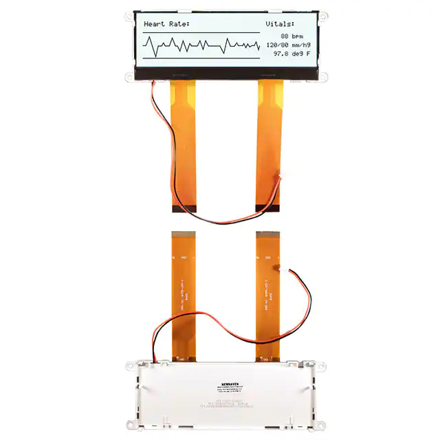


 工商网监
湘ICP备2023018690号
工商网监
湘ICP备2023018690号