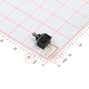
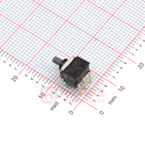
Digital Output Modules for Compact FieldPoint
NI cFP-DO-400, NI cFP-DO-401, NI cFP-DO-403, NI cFP-DO-410
• 8 or 16 digital outputs • 5 VDC • 12 VDC • 24 VDC • Fused outputs for short circuit protection cFP-DO-410 • 2,300 Vrms bank isolation for transient overvoltage protection • Hot-swappable with autoconfiguration • -40 to 70 °C operating range
Module cFP-DO-400 cFP-DO-401 cFP-DO-403 cFP-DO-410
Output Channels 8 16 16 8
Output Ranges 10 to 30 VDC, sourcing 10 to 30 VDC, sourcing 5 to 30 VDC, sinking 5 to 30 VDC, sourcing
Output Current Rating (see Specifications for More Details) 1.5 A 1.5 A 2A 1A
Compatibility Examples 12 and 24 VDC 12 and 24 VDC 5, 12, and 24 VDC 5, 12, and 24 VDC
Electronically Fused Outputs – – – �
All Channel Update Rate 20 KHz 20 KHz 20 KHz 20 KHz
Overview
The National Instruments cFP-DO-4xx devices are versatile digital output modules for Compact FieldPoint that you can use to control digital signals ranging from 5 to 30 V. These modules are commonly used to control indicator lights, external relays, and CMOS and TTL devices. All the modules include onboard diagnostics to ensure trouble-free installation and maintenance.
Digital Output Modules
The cFP-DO-4xx modules provide built-in module-to-module isolation to protect your Compact FieldPoint system and controller or communication interface from high voltage levels. All the digital output modules use a common ground plane for the digital output channels. The cFP-DO-400 and cFP-DO-401 sourcing digital output modules are capable of providing up to 2 A per channel, with a maximum power limit across the entire module as explained in the specifications section.
The cFP-DO-403 sinking digital output module is capable of providing up to 2 A per channel, with a maximum power limit across the entire module as explained in the specifications section. The cFP-DO-410 sourcing digital output module is capable of providing up to 1 A per channel. It also features an electronic fuse that prevents damage to the module due to short circuits or other overcurrent situations. The fuses automatically reset when the output returns to a normal state. An LED indicates an overcurrent fault. All the channels on the cFP-DO-4xx modules feature LEDs that indicate the output state of each channel. The modules feature an all-channel update rate of 20 kHz. Overall data throughput depends on software loop speeds and network speeds.
Isolation
The cFP-DO-4xx modules feature optical bank isolation with 2,300 Vrms of breakdown isolation. These Compact FieldPoint modules do not have channel-to-channel isolation.
�Digital Output Modules for Compact FieldPoint
Field I/O Connections
Compact FieldPoint modules include a built-in power distribution bus that offers multiple power connections on the module. A field-wired power supply connected to the voltage (V) and common (C) terminals is internally connected to a power distribution bus that provides additional breakout terminals for voltage supply (VSUP) and common (COM). These terminals deliver a convenient way to distribute power to field devices that require external power. Each cFP-DO-400 and cFP-DO-410 has: . . . . . . . . . . . . . . . . . . . . . . . . • 8 digital output terminals (VOUT) . . . . . . . . . . . . . . . . . . . . . . . . . . . • 16 common terminals (COM) . . . . . . . . . . . . . . . . . . . . . . . . . . . . . . • 8 power connections to power field devices (VSUP) . . . . . . . . . . . . . Each cFP-DO-401 and cFP-DO-403 has: • 16 digital output terminals (VOUT) • 8 common terminals (COM) • 8 power connections to power field devices (VSUP)
V
2 A Max User Supplied Fuse
5 to 30 VDC External Power Supply 5 to 30 VDC External Power Supply 2 A Max User Supplied Fuse
–
V V
SUP OUT
+
V V SUP
Load
+ –
VOUT
Load
COM VOUT C
1.5 A Max User Supplied Fuse
cFP-DO-403
COM
Load
Figure 1. Wiring Schematics for Digital Output Modules
cFP-DO-400/401/410
C
To next channel
Ordering Information
NI cFP-DO-400 NI cFP-DO-401 NI cFP-DO-403 NI cFP-DO-410 ....................................................................777318-400 ....................................................................777318-401 ....................................................................777318-403 ....................................................................777318-410
Recommended Compact FieldPoint System Products NI cFP-2020 ......................................................................777317-2020 NI cFP-BP-4 ............................................................................778617-04 NI cFP-CB-1............................................................................778618-01 NI PS-4 power supply............................................................778805-90 NI Developer Suite Professional Control Edition..................777906-03
BUY NOW!
For complete product specifications, pricing, and accessory information, call 800 813 3693 (U.S.) or go to ni.com/info and enter cfpdo400, cfpdo401, cfpdo403, and/or cfpdo410.
BUY ONLINE a t ni.com o r CALL 800 813 3693 (U.S.)
2
�Digital Output Modules for Compact FieldPoint
Environment
Operating temperature ....................... -40 to 70 °C Storage temperature........................... -55 to 85 °C Relative humidity ................................ 10 to 90%, noncondensing
Specifications
Typical for -40 to 70 °C unless otherwise noted.
Digital Output Channels
Number of output channels cFP-DO-400, cFP-DO-410 ................ 8 cFP-DO-401, cFP-DO-403 ................ 16 Voltage range...................................... 5 to 30 VDC Output impedance at 10 to 30 V ........ 0.3 (0.3 V drop at 1 A) cFP-DO-403 ..................................... 0.12 Ω Output impedance at 5 to 10 V .......... 2 Ω Maximum output current per channel at 10 to 30 V range cFP-DO-400, cFP-DO-401 ................ 1.5 A cFP-DO-403 ..................................... 2.0 A cFP-DO-410 ..................................... 1 A Maximum output current on all channels cFP-DO-400 ..................................... 8 A2 cFP-DO-401 ..................................... 8 A2 cFP-DO-403 ..................................... 16 A2 at -40 to 60 °C 12 A2 at 60 to 70 °C cFP-DO-410 ..................................... 8 A Maximum output current at 5 to 10 V range Per channel ..................................... 0.67 A All channels, cFP-DO-4001 .............. 1.35 A2 All channels, cFP-DO-4011 .............. 1.2 A2 Output delay time Turn ON........................................... 20 µs Turn OFF .......................................... 50 µs Protection Flyback diode to COM for inductive loads Leakage, overcurrent condition Power-on state.................................... Off, until set to power-on state stored in local network module
1The
Shock and Vibration
Operating vibration, random (IEC 60068-2-64) ............................. 10 to 500 Hz, 5 grms Operating vibration, sinusoidal (IEC 60068-2-6) ............................... 10 to 500 Hz, 5 g Operating shock (IEC 60068-2-27) ............................. 50 g, 3 ms half sine, 18 shocks at 6 orientations; 30 g, 11 ms half sine, 18 shocks at 6 orientations
Safety and Compliance
Safety
This product is designed to meet the requirements of the following standards of safety for electrical equipment for measurement, control, and laboratory use: • IEC 61010-1, EN 61010-1 • UL 61010-1, CSA 61010-1 Note: For UL and other safety certifications, refer to the product label or visit ni.com/certification, search by model number or product line, and click the appropriate link in the Certification column.
Electromagnetic Compatibility
This product is designed to meet the requirements of the following standards of EMC for electrical equipment for measurement, control, and laboratory use: • EN 61326 EMC requirements; Minimum Immunity • EN 55011 Emissions; Group 1, Class A • CE, C-Tick, ICES, and FCC Part 15 Emissions; Class A Note: For EMC compliance, operate this device according to product documentation.
sum of the squares of the output currents on every channel must be less than or equal to this value.
Power Requirements
Power from network module cFP-DO-400 ..................................... 300 mW cFP-DO-401 and cFP-DO-403 .......... 600 mW cFP-DO-410 ..................................... 400 mW
CE Compliance
This product meets the essential requirements of applicable European Directives, as amended for CE marking, as follows: • 2006/95/EC; Low-Voltage Directive (safety) • 2004/108/EC; Electromagnetic Compatibility Directive (EMC) Note: Refer to the Declaration of Conformity (DoC) for this product for any additional regulatory compliance information. To obtain the DoC for this product, visit ni.com/certification, search by model number or product line, and click the appropriate link in the Certification column.
Isolation Voltage
Channel-to-channel isolation.............. No isolation between channels Transient overvoltage.......................... 2,300 Vrms
Physical Characteristics
LED indicators POWER (green) ............................... READY (green) ................................ or (green) .............. Dimensions (including terminal base) Power on and self-test passed Module configured and ready On/off state of each channel 10.7 by 10.9 by 9.1 cm (4.2 by 4.3 by 3.6 in.) Weight................................................. 136 g (4.8 oz)
Waste Electrical and Electronic Equipment (WEEE)
EU Customers: At the end of their life cycle, all products must be sent to a WEEE recycling center. For more information about WEEE recycling centers and National Instruments WEEE initiatives, visit ni.com/environment/weee.htm.
BUY ONLINE a t ni.com o r CALL 800 813 3693 (U.S.)
3
�NI Services and Support
IN TA
PL
SERVICE NEEDS
LO Y
V DE
NI has the services and support to meet your needs around the globe and through the application life cycle – from planning and development through deployment and ongoing maintenance. We offer services and service levels to meet customer requirements in research, design, validation, and manufacturing. Visit ni.com/services.
Local Sales and Technical Support
In offices worldwide, our staff is local to the country, giving you access to engineers who speak your language. NI delivers industry-leading technical support through online knowledge bases, our applications engineers, and access to 14,000 measurement and automation professionals within NI Developer Exchange forums. Find immediate answers to your questions at ni.com/support. We also offer service programs that provide automatic upgrades to your application development environment and higher levels of technical support. Visit ni.com/ssp.
MA IN
Training and Certification
NI training is the fastest, most certain route to productivity with our products. NI training can shorten your learning curve, save development time, and reduce maintenance costs over the application life cycle. We schedule instructor-led courses in cities worldwide, or we can hold a course at your facility. We also offer a professional certification program that identifies individuals who have high levels of skill and knowledge on using NI products. Visit ni.com/training.
EL OP
AN
Professional Services
Our NI Professional Services team is composed of NI applications and systems engineers and a worldwide National Instruments Alliance Partner program of more than 600 independent consultants and integrators. Services range from start-up assistance to turnkey system integration. Visit ni.com/alliance.
OEM Support
We offer design-in consulting and product integration assistance if you want to use our products for OEM applications. For information about special pricing and services for OEM customers, visit ni.com/oem.
P DE
Hardware Services
NI Factory Installation Services
NI Factory Installation Services (FIS) is the fastest and easiest way to use your PXI or PXI/SCXI combination systems right out of the box. Trained NI technicians install the software and hardware and configure the system to your specifications. NI extends the standard warranty by one year on hardware components (controllers, chassis, modules) purchased with FIS. To use FIS, simply configure your system online with ni.com/pxiadvisor.
Calibration Services
NI recognizes the need to maintain properly calibrated devices for high-accuracy measurements. We provide manual calibration procedures, services to recalibrate your products, and automated calibration software specifically designed for use by metrology laboratories. Visit ni.com/calibration.
Repair and Extended Warranty
NI provides complete repair services for our products. Express repair and advance replacement services are also available. We offer extended warranties to help you meet project life-cycle requirements. Visit ni.com/services.
ni.com • 800 813 3693
National Instruments • info@ni.com
*351564B-01*
351564B-01 2008-9484-161-101-D
©2008 National Instruments Corporation. All rights reserved. FieldPoint, National Instruments, National Instruments Alliance Partner, NI, ni.com, NI Developer Suite, and SCXI are trademarks of National Instruments. Other product and company names listed are trademarks or trade names of their respective companies. A National Instruments Alliance Partner is a business entity independent from NI and has no agency, partnership, or joint-venture relationship with NI.
�