DECOUPLING DEVICE FOR HIGH FREQUENCY
F18
Higher Capacitance.
Low ESR, Low ESL, High ripple current.
Resin-molded Chip.
Designed for surface mounting on high density PC board.
Two terminals product for high frequency.
Compliant to the RoHS directive (2002/95/EC).
Specifications
Item
Performance Characteristics
Category Temperature Range −55 to +105°C
Capacitance Tolerance ±20% (at 120Hz)
Dissipation Factor
Refer to next table
ESR
Refer to next table
Leakage Current
After 5 minute’s application of rated voltage,
leakage current is not more than 0.1CV
At 60°C 90%RH 500hours (No voltage applied)
Capacitance Change..Within −20 to +30% of the initial specified value
Dissipation Factor.......200% or less than the Initial specified value
ESR............................200% or less than the Initial specified value
Leakage Current.........Initial specified value or less
Damp Heat
(Steady State)
−55°C / +105°C 30minutes each 5cycle
Capacitance Change..Within ±20% of the Initial specified value
Dissipation Factor.......200% or less than the Initial specified value
ESR ............................200% or less than the Initial specified value
Leakage Current.........Initial specified value or less
Temperature Cycles
Type numbering system (Example : 2.5V 33µF)
1
2
4
3
5
6
7
8
9
10
11
Temperature Change Capacitance Change
Dissipation Factor
Characteristics
ESR
Leakage Current
F 1 8 0 E 3 3 6 M C C
Series
Case
Rated
code
capacitance
Rated voltage
Capacitance
tolerance
Taping code
(Refer to page 325 for details)
−55°C
+105°C
Within −20 to +0%
Initial specified value or less
Initial specified value or less
Initial specified value or less
Within −0 to +50%
150% or less than the Initial specified value
150% or less than the Initial specified value
10 times Initial specified value
Capacitor meets the following characteristics after solder reflow
(Peak: 240°C for 10sec, 2cycle).
Temperature should be measured at the terminals.
Resistance
to Soldering Heat
Capacitance Change..Within ±20% of the Initial specified value
Dissipation Factor.......Initial specified value or less
ESR............................Initial specified value or less
Leakage Current.........Initial specified value or less
After application of 115% of rating voltage at the rate of
30 seconds ON, 30 seconds OFF, for 1000 successive
test cycles at 105°C, capacitors meet the characteristics
requirements listed below.
Surge
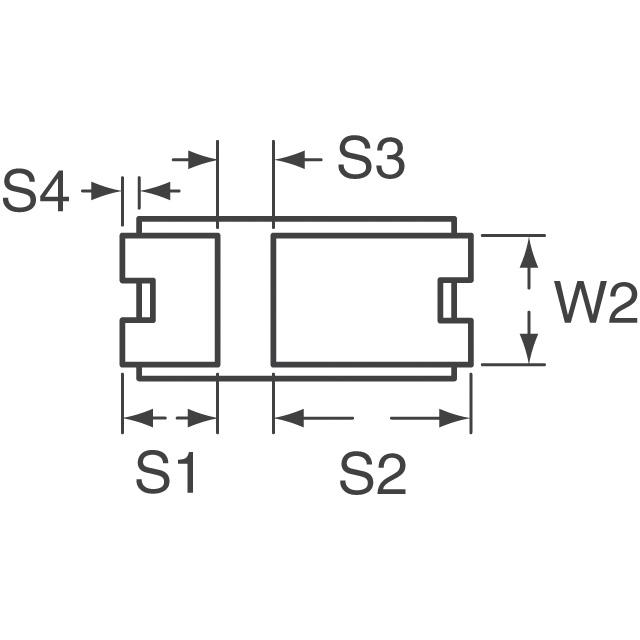
Dimensions
Capacitance Change...Within ±20% of the initial specified value
Dissipation Factor.........200% or less than the Initial specified value
ESR ..............................200% or less than theInitial specified value
Leakage Current...........Initial specified value or less
L1
S4
J336
L2
W1
S3
S1
After 2000 hours’ application of rated voltage at 105°C, they will meet
the specified value for life charecteristics listed below.
W2
S2
Capacitance Change....Within ±20% of the initial value
Dissipation Factor.........200% or less than the Initial specified value
ESR ..............................200% or less than the Initial specified value
Leakage Current...........Initial specified value or less
Endurance
H
T
Printed on the package top.
Marking
(mm)
Case Code
L1
L2
W1
W2
H
C
6.5 ± 0.2
6.0 ± 0.2
3.2 ± 0.2
2.5 ± 0.2
1.9MAX.
T
S1
S3
S4
1.0 ± 0.2
(0.25)
S2
1.0 ± 0.2 1.65 ± 0.2 3.85 ± 0.2
S 4 dimension only for refence
Marking
Standard ratings
V
Cap.(µF)
J336
Rated Capacitance
22
33
47
68
100
Code
2.5
0E
226
336
476
686
107
C
C
C
(C)
4
0G
C
C
C
(C)
6.3
0J
C
C
(C)
(Capacitance code)
Rated Voltage (Voltage code)
( ) The series in parentheses are being developed.
Please contact to your local Nichicon sales office when
these series are being designed in your application.
CAT.8100Y
�DECOUPLING DEVICE FOR HIGH FREQUENCY
F18
Ratings Table
< Standard >
Rated Volt
(V)
Rated
Capacitance
(µF)
Case
code
Part Number
Leakage
Current
(µA)
Disspation
Factor
(% @120Hz)
0033
C
F180E336MCC
0008.3
05
70.0
1.1
0047
C
F180E476MCC
0011.8
05
70.0
1.1
0068
C
F180E686MCC
0017.0
05
60.0
1.2
0022
C
F180G226MCC
0008.8
05
70.0
1.1
0033
C
F180G336MCC
0013.2
05
70.0
1.1
0047
C
F180G476MCC
0018.8
05
60.0
1.2
0022
C
F180J226MCC
0013.9
05
70.0
1.1
0033
C
F180J336MCC
0020.8
05
60.0
1.2
2.5
4.0
6.3
ESR
Rated Ripple
(mΩ@100kHz) (Arms@100kHz)
Layout Land Pattern (Example)
a3
a1
b4
a2
b2
b1
b4
b3
(mm)
Case
C
a1
3.0
a2
1.0
a3
1.0
b1
2.25
b2
2.0
b3
3.45
b4
1.05
The land for high density implemention (The fillet forms even following dimensions)
Case
C
a1
2.7
a2
1.0
a3
0.85
b1
1.95
b2
2.0
b3
3.15
b4
0.75
Frequency characteristic
〔
The characteristics are measured by a network
analyzer and converted from S21 to impedance.
〕
10000
Impedance (m½)
1000
100
F18 6.3V-47µF (C)
10
1
100k
1M
10M
100M
1G
10G
Frequency (Hz)
< Notice > The graph illustrates representative data.
Please use this for reference only.
CAT.8100Y
�
很抱歉,暂时无法提供与“F180G476MCC”相匹配的价格&库存,您可以联系我们找货
免费人工找货