0
登录后你可以
  • 下载海量资料
  • 学习在线课程
  • 观看技术视频
  • 写文章/发帖/加入社区
会员中心
创作中心
发布
  • 发文章

  • 发资料

  • 发帖

  • 提问

  • 发视频

创作活动
F930J477KNC

F930J477KNC

  • 厂商:

    NICHICON(尼吉康)

  • 封装:

    X7343-43

  • 描述:

    钽电容 X7343-43 470µF ±10% 6.3V 300mΩ 7.30 x 4.30mm 3.00mm

  • 详情介绍
  • 数据手册
  • 价格&库存
F930J477KNC 数据手册
SOLID TANTALUM ELECTROLYTIC CAPACITORS F93 Resin-molded Chip, Standard Series Specifications Compliant to the RoHS directive (2002/95/EC). Item Category Temperature Range Capacitance Tolerance Dissipation Factor (120Hz) ESR (100kHz) Leakage Current Capacitance Change by Temperature Damp Heat (Steady State) Type numbering system (Example: 10V 10µF) 1 2 3 4 5 6 7 8 9 10 F 9 3 1 A 1 0 6 M A 11 Taping code (Refer to page 333 for details) Case code Capacitance tolerance Rated capacitance Rated voltage Temperature Cycles Resistance to Soldering Heat Series Drawing A • B Case W1 L S S (mm) Case code A B C N 3.2 3.5 6.0 7.3 L ± 0.2 ± 0.2 ± 0.2 ± 0.2 W1 1.6 ± 0.2 2.8 ± 0.2 3.2 ± 0.2 4.3 ± 0.2 W2 1.2 ± 0.1 2.2 ± 0.1 2.2 ± 0.1 2.4 ± 0.1 H 1.6 ± 0.2 1.9 ± 0.2 2.5 ± 0.2 2.8 ± 0.2 20V 25V 35V (Capacitance code) N Case 47 16V 22 16V C685 G J A C C Case 1mm B Case 100 16V A Case (Rated voltage code) Terminal Strength Keeping a capacitor surface-mounted on a substrate upside down and supporting the substrate at both of the opposite bottom points 45mm apart from the center of 20 capacitor, the pressure strength is R230 applied with a specified jig at the center of substrate so that the substrate may bend by 1mm as illustrated. Then, there shall be found 45 45 no remarkable abnormality on the capacitor terminals. S 0.8 ± 0.2 0.8 ± 0.2 1.3 ± 0.2 1.3 ± 0.2 Marking 4V 6.3V 10V 16V Shear Test After applying the pressure load of 5N for 10±1 seconds horizontally to the center of capacitor side body which has no electrode and has been soldered beforehand on a substrate, there shall be ¥ found neither exfoliation nor its sign at the 5N (0.51kg f) For 10±1 seconds terminal electrode. S Dimensions 10 seconds reflow at 260˚C , 5 seconds immersion at 260˚C Capacitance Change...Refer to next page (* 1) Dissipation Factor........Initial specified value or less Leakage Current..........Initial specified value or less Endurance∗ W2 S --55˚C / +125˚C 30 minutes each 5 cycles Capacitance Change...Refer to next page (* 1) Dissipation Factor........Initial specified value or less Leakage Current..........Initial specified value or less After 2000 hours' application of rated voltage in series with a 3Ω resistor at 85 ˚C , or derated voltage in series with a 3 Ω resistor at 125 ˚C , capacitors shall meet the characteristic requirements table below. Capacitance Change......Refer to next page (* 1) Dissipation Factor..........Initial specified value or less Leakage Current............Initial specified value or less H W2 Refer to next page • After 1 minute's application of rated voltage, leakage current at 20˚C is not more than 0.01CV or 0.5µA, whichever is greater. • After 1 minute's application of rated voltage, leakage current at 85˚C is not more than 0.1CV or 5µA, whichever is greater. • After 1 minute's application of derated voltage, leakage current at 125˚C is not more than 0.125CV or 6.3µA, whichever is greater. +15% Max. (at +125˚C) +10% Max. (at +85˚C) --10% Max. (at --55˚C) At 40˚C 90 to 95% R.H. 500 hours (No voltage applied) Capacitance Change...Refer to next page (* 1) Dissipation Factor........Initial specified value or less Leakage Current..........Initial specified value or less Surge∗ W1 H --55 to +125˚C (Rated temperature : +85˚C) ± 20%, ±10% (at 120Hz) Refer to next page After application of surge voltage in series with a 33Ω resistor at the rate of 30 seconds ON, 30 seconds OFF, for 1000 successive test cycles at 85˚C, capacitors shall meet the characteristic requirements table below. Capacitance Change.....Refer to next page (* 1) Dissipation Factor.........Initial specified value or less Leakage Current...........Initial specified value or less C • N Case L Performance Characteristics ∗ As for the surge and derated voltage at 125˚C, refer to page 332 for details. Rated voltage (V) Capacitance (µF) Rated voltage (V) D E V We can supply the type of compliance to AEC-Q200. Please contact to your local Nichicon sales office when these series are being designed in your application. Standard Ratings V Cap. (µF) 0.68 1 1.5 2.2 3.3 4.7 6.8 10 15 22 33 47 68 100 150 220 330 470 680 Code 684 105 155 225 335 475 685 106 156 226 336 476 686 107 157 227 337 477 687 4 0G 6.3 0J 10 1A 16 1C 20 1D 25 1E A A A A A A A A A A A A•B B (A) • B • C C N N A A A A A •B A •B A•B•C B•C B•C •N N N A A A A •B A•B A•B•C B•C B•C•N C•N N N A A A A A •B A•B A•B •C B •C (B) • C • N N C•N N N A A A • • • B B B C B• C C• N C• N (N) A •B B•C C C •N N N 35 1V A A A A •B B B•C C C N N ( ) The series in parentheses are being developed. Please contact to your local Nichicon sales office when these series are being designed in your application. CAT.8100B SOLID TANTALUM ELECTROLYTIC CAPACITORS F93 Standard Ratings Rated Rated Volt Capacitance (µF) 4V 6.3V 10V 22 33 47 68 100 100 150 220 220 330 470 680 10 15 22 33 47 47 68 68 100 100 100 150 150 220 220 220 330 470 6.8 10 15 22 22 33 33 47 47 47 68 68 100 100 100 150 150 220 330 Case code Part Number Leakage Current (µA) A A A A A B B B C C N N A A A A A B A B A B C B C B C N N N A A A A B A B A B C B C B C N C N N N F930G226MAA F930G336MAA F930G476MAA F930G686MAA F930G107MAA F930G107MBA F930G157MBA F930G227MBA F930G227MCC F930G337MCC F930G477MNC F930G687MNC F930J106MAA F930J156MAA F930J226MAA F930J336MAA F930J476MAA F930J476MBA F930J686MAA F930J686MBA F930J107MAA F930J107MBA F930J107MCC F930J157MBA F930J157MCC F930J227MBA F930J227MCC F930J227MNC F930J337MNC F930J477MNC F931A685MAA F931A106MAA F931A156MAA F931A226MAA F931A226MBA F931A336MAA F931A336MBA F931A476MAA F931A476MBA F931A476MCC F931A686MBA F931A686MCC F931A107MBA F931A107MCC F931A107MNC F931A157MCC F931A157MNC F931A227MNC F931A337MNC 0.9 1.3 1.9 2.7 4.0 4.0 6.0 8.8 8.8 13.2 18.8 27.2 0.6 0.9 1.4 2.1 3.0 3.0 4.3 4.3 6.3 6.3 6.3 9.5 9.5 13.9 13.9 13.9 20.8 29.6 0.7 1.0 1.5 2.2 2.2 3.3 3.3 4.7 4.7 4.7 6.8 6.8 10.0 10.0 10.0 15.0 15.0 22.0 33.0 Disspation *1 ESR ∆C/C Factor (%@120Hz) (Ω@100kHz) (%) 6 8 18 24 30 14 16 18 12 14 16 18 6 6 8 8 18 6 20 8 35 14 8 18 12 30 14 10 14 16 6 6 8 12 6 18 8 40 8 6 12 8 18 10 8 14 10 12 18 2.5 2.5 2.5 2.5 2.0 0.9 0.7 0.7 0.7 0.7 0.3 0.3 3.0 2.9 2.5 2.5 2.5 1.0 2.0 1.0 2.0 0.9 0.7 0.9 0.7 1.2 0.7 0.5 0.5 0.3 3.5 3.0 2.9 2.5 1.9 2.5 1.4 2.0 1.0 0.9 0.9 0.8 1.2 0.7 0.6 0.7 0.6 0.5 0.5 ∗ ∗ ∗ ∗ ∗ ∗ ∗ ∗ ∗ ∗ ∗ ∗ ∗ ∗ ∗ ∗ ∗ ∗ ∗ ∗ ± 15 ∗ ∗ ∗ ∗ ± 15 ∗ ∗ ∗ ∗ ∗ ∗ ∗ ∗ ∗ ∗ ∗ ± 15 ∗ ∗ ± 15 ∗ ± 15 ∗ ∗ ∗ ∗ ∗ ∗ Rated Rated Volt Capacitance (µF) 16V 20V 25V 35V *1 : ∆C/C Marked "∗" Item Damp Heat Tempereature cycles Resistance soldering heat Surge Endurance A • B • C • N Case (%) ±10 ±5 ±5 ±5 ±10 1 2.2 3.3 4.7 6.8 10 10 15 15 22 22 22 33 33 47 47 68 100 100 150 220 2.2 3.3 4.7 4.7 6.8 6.8 10 10 15 22 22 33 33 47 47 1 1.5 2.2 3.3 4.7 4.7 10 10 15 22 22 33 47 0.68 1 1.5 2.2 2.2 3.3 4.7 4.7 6.8 10 15 22 Case code Part Number Leakage Current (µA) A A A A A A B A B A B C B C C N N C N N N A A A B A B A B C B C C N C N A A A A A B B C C C N N N A A A A B B B C C C N N F931C105MAA F931C225MAA F931C335MAA F931C475MAA F931C685MAA F931C106MAA F931C106MBA F931C156MAA F931C156MBA F931C226MAA F931C226MBA F931C226MCC F931C336MBA F931C336MCC F931C476MCC F931C476MNC F931C686MNC F931C107MCC F931C107MNC F931C157MNC F931C227MNC F931D225MAA F931D335MAA F931D475MAA F931D475MBA F931D685MAA F931D685MBA F931D106MAA F931D106MBA F931D156MCC F931D226MBA F931D226MCC F931D336MCC F931D336MNC F931D476MCC F931D476MNC F931E105MAA F931E155MAA F931E225MAA F931E335MAA F931E475MAA F931E475MBA F931E106MBA F931E106MCC F931E156MCC F931E226MCC F931E226MNC F931E336MNC F931E476MNC F931V684MAA F931V105MAA F931V155MAA F931V225MAA F931V225MBA F931V335MBA F931V475MBA F931V475MCC F931V685MCC F931V106MCC F931V156MNC F931V226MNC 0.5 0.5 0.5 0.8 1.1 1.6 1.6 2.4 2.4 3.5 3.5 3.5 5.3 5.3 7.5 7.5 10.9 16.0 16.0 24.0 35.2 0.5 0.7 0.9 0.9 1.4 1.4 2.0 2.0 3.0 4.4 4.4 6.6 6.6 9.4 9.4 0.5 0.5 0.6 0.8 1.2 1.2 2.5 2.5 3.8 5.5 5.5 8.3 11.8 0.5 0.5 0.5 0.8 0.8 1.2 1.6 1.6 2.4 3.5 5.3 7.7 Disspation *1 ESR ∆C/C Factor (%@120Hz) (Ω@100kHz) (%) 4 4 4 6 6 6 6 10 6 15 8 6 8 6 8 6 6 15 10 15 25 4 4 6 6 6 6 8 6 6 8 8 8 6 10 8 4 4 6 6 8 6 12 6 8 8 6 8 8 4 4 6 6 4 4 8 6 6 6 6 8 7.5 5.0 4.5 4.0 3.5 3.0 2.0 3.0 2.0 3.0 1.9 1.1 1.9 1.1 0.9 0.7 0.6 0.7 0.6 0.6 0.7 5.0 4.5 3.0 2.8 3.5 2.5 3.5 2.1 1.2 1.9 1.1 1.1 0.7 1.1 0.7 7.5 6.7 6.3 6.0 4.0 2.8 1.9 1.5 1.2 1.1 0.7 0.7 0.7 7.6 7.5 7.5 7.0 3.8 3.5 3.1 1.8 1.8 1.6 0.7 0.7 ∗ ∗ ∗ ∗ ∗ ∗ ∗ ∗ ∗ ± 15 ∗ ∗ ∗ ∗ ∗ ∗ ∗ ± 10 ∗ ∗ ± 10 ∗ ∗ ∗ ∗ ∗ ∗ ∗ ∗ ∗ ∗ ∗ ∗ ∗ ∗ ∗ ∗ ∗ ∗ ∗ ∗ ∗ ∗ ∗ ∗ ∗ ∗ ∗ ∗ ∗ ∗ ∗ ∗ ∗ ∗ ∗ ∗ ∗ ∗ ∗ ∗ In case of capacitance tolerance ±10% type, K will be put at 9th digit of type numbering system. CAT.8100B
F930J477KNC AI解析
物料型号:SOLID TANTALUM ELECTROLYTIC CAPACITORS,即固体钽电解电容器。

器件简介:这是nichicon F93系列的树脂封装标准型SMD电容器,符合RoHS指令(2002/95/EC)。

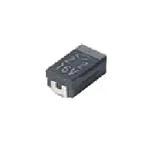
引脚分配:文档中没有提供具体的引脚分配图,但通常SMD电容器的引脚分配是对称的,两端为电容器的正负极。

参数特性: - 类别温度范围:-55至+125°C(额定温度:+85°C) - 电容公差:+20%,±10%(在120Hz时) - 耗散因子(120Hz)和等效串联电阻(ESR,100kHz):详见下一页 - 漏电流:在20°C时,额定电压下1分钟后的漏电流不超过0.01CV或0.5μA(取较大值);在85°C时,不超过0.1CV或5μA;在125°C时,不超过0.125CV或6.3μA。 - 电容温度变化:在+125°C时最大+15%,在+85°C时最大+10%,在-55°C时最大-10%。

功能详解:文档提供了详细的性能特性表,包括温度循环、耐焊接热性、冲击测试、端子强度测试等。

应用信息:文档提到可以提供符合AEC-Q200标准的类型,并建议在设计应用时联系当地的Nichicon销售办公室。

封装信息:提供了不同尺寸的封装代码和对应的尺寸数据,例如长度(L)、宽度(W)、高度(H)和端子间距(S)。
*介绍内容由AI识别生成
F930J477KNC 价格&库存

很抱歉,暂时无法提供与“F930J477KNC”相匹配的价格&库存,您可以联系我们找货

免费人工找货