ALUMINUM ELECTROLYTIC CAPACITORS
UUG
Chip Type, Higher Capacitance Range
Chip Type , higher capacitance in larger case sizes (φ12.5, φ16, φ18)
Designed for surface mounting on high density PC board.
Applicable to automatic mounting machine fed with carrier tape.
Compliant to the RoHS directive (2011/65/EU,(EU)2015/863).
AEC-Q200 compliant. Please contact us for details.
UUJ
Wide
Temperature
UUG
Specifications
Item
Performance Characteristics
–40 to +85°C
6.3 to 450V
4.7 to 10000µF
± 20% at 120Hz, 20°C
Category Temperature Range
Rated Voltage Range
Rated Capacitance Range
Capacitance Tolerance
Rated voltage (V)
6.3 to 100
—
After 1 minute's application of rated voltage at 20°C, leakage current is not
more than 0.03CV or 4 (µA), whichever is greater.
Leakage Current
160 to 450
I = 0.04CV+100 ( µA) max.
(1 minute's at 20°C)
Measurement frequency : 120Hz at 20°C
Tangent of loss angle (tan δ)
Rated voltage (V)
tan δ (MAX.)
6.3
0.28
10
0.24
16
0.20
25
0.16
35
0.14
50
0.12
63
0.10
100
0.08
160 to 250 400 • 450
0.25
0.20
For capacitance of more than 1000µF, add 0.02 for every increase of 1000µF. ( φ12.5 to φ18 )
Measurement frequency: 120Hz
Stability at Low Temperature
Rated voltage (V)
Z–25°C / Z+20°C
Z–40°C / Z+20°C
Impedance ratio
(MAX.)
6.3
5
12
10
4
10
16
3
8
25
2
5
35
2
4
50
2
3
Capacitance change
tan δ
Leakage current
63
2
3
100
2
3
160 to 250 400 • 450
3
6
6
10
Endurance
The specifications listed at right shall be met when the
capacitors are restored to 20°C after the rated voltage is
applied for 2000 hours at 85°C.
Shelf Life
After storing the capacitors under no load at 85°C for 1000 hours and then performing voltage treatment based on JIS C 5101-4
clause 4.1 at 20°C, they shall meet the specified values for the endurance characteristics listed above.
Marking
Black print on the case top.
Plastic platform
Capacitance
L ±1.0
Pressure
relief vent
L ±1.0
1
2
3
H
12.5×13.5
4.8
12.5×13.5
13.6
4.8
13.6
13.6
4.0
13.6
13.5
1.04.0
to 1.4
13.5
1.0 to 1.4
12.5×16.
4.8
12.5×16.
13.6
4.8
13.6
13.6
4.0
13.6
16.0
1.04.0
to 1.4
16.0
1.0 to 1.4
12.5×21.
4.8
12.5×21.
13.6
4.8
13.6
13.6
4.0
13.6
21.0
1.04.0
to 1.4
21.0
1.0 to 1.4
16×16.5.
5.4
16×16.5.
17.1
5.4
17.1
17.1
6.3
17.1
16.5
1.06.3
to 1.4
16.5
1.0 to 1.4
8
9
10 11 12 13
14
Capacitance Tolerance (±20%)
Rated capacitance (330µF)
A ±0.2
Negative
18×16.5.
6.4
18×16.5.
19.1
6.4
19.1
19.1
6.3
19.1
16.5
1.06.3
to 1.4
16.5
1.0 to 1.4
7
Size code
Negative
16×21.5.
5.4
16×21.5.
17.1
5.4
17.1
17.1
6.3
17.1
21.5
1.06.3
to 1.4
21.5
1.0 to 1.4
6
Configuration
Rated voltage (50V)
Series name
(mm)
φD
A
φD
B
A
C
B
E
C
L
E
H
L
H
5
Package code
H
Series
4
U U G 1 H 3 3 1 M NQ 1 M S
EA ±0.2A ±0.2
E
Pressure
relief vent
Positive
Type numbering system (Example : 50V 330µF)
A ±0.2
Series
C ±0.2
B ±0.2 B ±0.2
0.3 MAX.
φD ±0.5φD ±0.5
Voltage
Lot No.
330 µF 330 µF
UG 50VUG 50V
H1015 H1015
Trade mark
n i c h i c onni c h i c o n
0.3 MAX.
Plastic platform
Capacitance
Positive
C ±0.2
Voltage
Lot No.
0.5 MAX. 0.5 MAX.
Chip Type
Trade mark
Within ±20% of the initial capacitance value
200% or less than the initial specified value
Less than or equal to the initial specified value
Type
18×21.5.
(mm)
6.4
18×21.5.
19.1
6.4
19.1
19.1
6.3
19.1
21.5
1.06.3
to 1.4
21.5
1.0 to 1.4
The vibration structure-resistant product is also available upon request,
please ask for details.
Frequency coefficient of rated ripple current
V
6.3 to 100
160 to 450
Cap.(µF)
Frequency
68
100 to 4700
1000 to 10000
4.7 to 100
50Hz
0.75
0.80
0.85
0.80
120Hz
1.00
1.00
1.00
1.00
300Hz
1.35
1.23
1.10
1.25
1kHz
1.57
1.34
1.13
1.40
10kHz or more
2.00
1.50
1.15
1.60
Dimension table in next page.
CAT.8100K
�ALUMINUM ELECTROLYTIC CAPACITORS
UUG
■ Dimensions
Rated Voltage
(V)
(code)
Rated
Capacitance
(µF)
2200
3300
3300
6.3
(0J)
10
(1A)
35
(1V)
Part Number
0.30
415.8
890
UUG0J222MNQ1MS
0.32
623.7
1200
UUG0J332MNQ1MS
0.32
623.7
1200
UUG0J332MNQ6MS
0.34
888.3
1400
UUG0J472MNQ1MS
0.38
1285.2
1650
UUG0J682MNQ1MS
6800
16 ×21.5
0.38
1285.2
1650
UUG0J682MNQ6MS
10000
18 ×21.5
0.46
1890
2000
UUG0J103MNQ1MS
1000
12.5× 13.5
0.24
300
620
UUG1A102MNQ1MS
2200
12.5× 16
0.26
660
960
UUG1A222MNQ1MS
3300
16×16.5
0.28
990
1300
UUG1A332MNQ1MS
4700
18 ×16.5
0.30
1410
1500
UUG1A472MNQ1MS
4700
16 ×21.5
0.30
1410
1500
UUG1A472MNQ6MS
6800
18 ×21.5
0.34
2040
1850
UUG1A682MNQ1MS
10000
18×21.5
0.42
3000
2200
UUG1A103MNQ6MS
1000
12.5×13.5
0.20
480
710
UUG1C102MNQ1MS
2200
16×16.5
12.5 ×21
0.22
1056
1150
UUG1C222MNQ1MS
0.22
1056
1150
UUG1C222MNQ6MS
3300
18× 16.5
0.24
1584
1450
UUG1C332MNQ1MS
3300
16× 21.5
0.24
1584
1450
UUG1C332MNQ6MS
2256
1750
UUG1C472MNQ1MS
550
UUG1E471MNQ1MS
4700
18× 21.5
0.26
470
12.5×13.5
0.16
2200
12.5×16
18× 16.5
352.5
0.16
750
820
UUG1E102MNQ1MS
0.18
1650
1350
UUG1E222MNQ1MS
2200
16× 21.5
0.18
1650
1350
UUG1E222MNQ6MS
3300
18× 21.5
0.20
2475
1700
UUG1E332MNQ1MS
470
12.5×13.5
0.14
1000
16× 16.5
0.14
1000
12.5× 21
18 ×21.5
493.5
1050
580
UUG1V471MNQ1MS
1000
UUG1V102MNQ1MS
0.14
1050
1000
UUG1V102MNQ6MS
0.16
2310
1550
UUG1V222MNQ1MS
220
12.5×13.5
0.12
330
450
UUG1H221MNQ1MS
330
12.5× 13.5
0.12
495
520
UUG1H331MNQ1MS
470
16× 16.5
12.5× 21
0.12
705
740
UUG1H471MNQ1MS
0.12
705
740
UUG1H471MNQ6MS
1000
18× 21.5
0.12
1500
1150
UUG1H102MNQ1MS
100
12.5× 13.5
0.10
189
370
UUG1J101MNQ1MS
220
12.5× 16
330
330
16× 16.5
415.8
580
UUG1J221MNQ1MS
623.7
680
UUG1J331MNQ1MS
0.10
623.7
680
UUG1J331MNQ6MS
0.10
888.3
850
UUG1J471MNQ1MS
470
16× 21.5
0.10
888.3
850
UUG1J471MNQ6MS
68
12.5× 13.5
0.08
204
350
UUG2A680MNQ1MS
100
220
12.5× 21
0.10
0.10
18× 16.5
470
100
(2A)
)
16 ×16.5
470
63
(1J)
12.5× 21
(
Rated Ripple
(mArms)
(85℃/120Hz)
18 ×16.5
2200
50
(1H)
16 ×16.5
Leakage Current
(µA)
at 20℃ after
1 minute
4700
1000
25
(1E)
12.5× 16
tan δ
6800
2200
16
(1C)
Case Size
φD×L(mm)
12.5× 16
18× 16.5
0.08
300
440
UUG2A101MNQ1MS
0.08
660
665
UUG2A221MNQ1MS
220
16× 21.5
0.08
660
665
UUG2A221MNQ6MS
330
18× 21.5
0.08
990
825
UUG2A331MNQ1MS
CAT.8100K
�ALUMINUM ELECTROLYTIC CAPACITORS
UUG
■ Dimensions
Rated Voltage
(V)
(code)
Rated
Capacitance
(µF)
47
68
160
(2C)
68
16×16.5
400.8
370
UUG2C470MNQ1MS
0.20
535.2
500
UUG2C680MNQ1MS
12.5×21
0.20
535.2
500
UUG2C680MNQ6MS
0.20
740
590
UUG2C101MNQ1MS
16×21.5
0.20
740
590
UUG2C101MNQ6MS
22
12.5× 13.5
0.20
276
235
UUG2D220MNQ1MS
33
12.5× 16
0.20
364
310
UUG2D330MNQ1MS
0.20
476
415
UUG2D470MNQ1MS
0.20
476
415
UUG2D470MNQ6MS
47
16× 16.5
12.5× 21
68
18× 16.5
0.20
644
505
UUG2D680MNQ1MS
68
16× 21.5
0.20
644
505
UUG2D680MNQ6MS
100
18× 21.5
0.20
900
590
UUG2D101MNQ1MS
10
12.5× 13.5
0.20
200
150
UUG2E100MNQ1MS
22
12.5× 16
0.20
320
240
UUG2E220MNQ1MS
0.20
430
340
UUG2E330MNQ1MS
33
16× 16.5
0.20
430
340
UUG2E330MNQ6MS
47
18× 16.5
0.20
570
415
UUG2E470MNQ1MS
47
16× 21.5
0.20
570
415
UUG2E470MNQ6MS
68
18× 21.5
0.20
780
490
UUG2E680MNQ1MS
12.5× 13.5
0.25
175.2
115
UUG2G4R7MNQ1MS
16× 16.5
0.25
260
140
UUG2G100MNQ1MS
4.7
10
12.5× 21
0.25
260
140
UUG2G100MNQ6MS
22
18× 16.5
0.25
452
280
UUG2G220MNQ1MS
22
16× 21.5
0.25
452
280
UUG2G220MNQ6MS
33
18× 21.5
0.25
628
350
UUG2G330MNQ1MS
47
4.7
10
450
(2W)
0.20
12.5×16
)
18×16.5
10
400
(2G)
Part Number
(
100
33
250
(2E)
Rated Ripple
(mArms)
(85℃/120Hz)
tan δ
100
47
200
(2D)
Leakage Current
(µA)
at 20℃ after
1 minute
Case Size
φD×L(mm)
10
12.5× 21
18× 21.5
0.25
852
430
UUG2G470MNQ6MS
12.5× 13.5
0.25
184.6
115
UUG2W4R7MNQ1MS
16× 16.5
0.25
280
140
UUG2W100MNQ1MS
0.25
280
140
UUG2W100MNQ6MS
12.5× 21
22
16× 21.5
0.25
496
275
UUG2W220MNQ1MS
33
18× 21.5
0.25
694
345
UUG2W330MNQ1MS
For taping specifications, recommended land size/soldering by
reflow and minimum order quantity, please refer to the Guidelines
for Aluminum Electrolytic Capacitors.
CAT.8100K
�Mouser Electronics
Authorized Distributor
Click to View Pricing, Inventory, Delivery & Lifecycle Information:
Nichicon:
UUG1V222MNS1MS UUG1V102MNQ1GS
�
很抱歉,暂时无法提供与“UUG1H471MNQ6ZD”相匹配的价格&库存,您可以联系我们找货
免费人工找货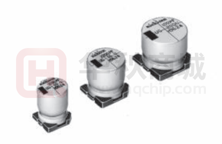


 工商网监
湘ICP备2023018690号
工商网监
湘ICP备2023018690号
