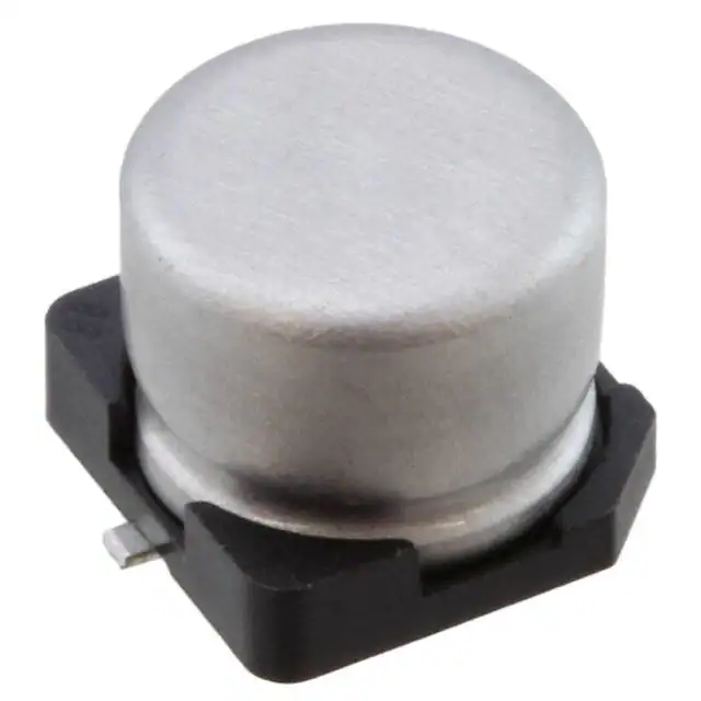
ALUMINUM ELECTROLYTIC CAPACITORS
UWP
5.5mmL Chip Type, Bi-Polarized
Designed for surface mounting on high density PC board.
Applicable to automatic mounting machine fed with carrier tape.
Compliant to the RoHS directive (2011/65/EU).
AEC-Q200 compliant. Please contact us for details.
UWX
Bi-polarized
UWP
Specifications
Item
Performance Characteristics
Category Temperature Range
–40 to +85°C
Rated Voltage Range
6.3 to 50V
Rated Capacitance Range
0.1 to 100µF
Capacitance Tolerance
±20% at 120Hz, 20°C
Leakage Current
After 2 minutes' application of rated voltage at 20°C, leakage current is not more than 0.05CV or 10 (µA) ,whichever is greater.
Measurement frequency : 120Hz at 20°C
6.3
0.24
Rated voltage (V)
tan δ (MAX.)
Tangent of loss angle (tan δ)
10
0.20
16
0.17
25
0.17
35
0.15
50
0.15
Measurement frequency : 120Hz
ZT / Z20 (MAX.)
Z– 40°C / Z+20°C
The specifications listed at right shall be met
when the capacitors are restored to 20°C after the
rated voltage is applied for 1000 hours at 85°C
with the polarity inverted every 250 hours.
Endurance
Within ±20% of the initial capacitance value
200% or less than the initial specified value
Less than or equal to the initial specified value
Capacitance change
tan δ
Leakage current
After storing the capacitors under no load at 85°C for 1000 hours and then performing voltage treatment based on JIS C 5101-4
clause 4.1 at 20°C, they shall meet the specified values for the endurance characteristics listed above.
The capacitors are kept on a hot plate for 30 seconds, which
Within ±10% of the initial capacitance value
Capacitance change
is maintained at 250°C. The capacitors shall meet the
Less than or equal to the initial specified value
tan δ
characteristic requirements listed at right when they are
Less than or equal to the initial specified value
Leakage current
removed from the plate and restored to 20°C.
Shelf Life
Resistance to soldering
heat
Marking
Black print on the case top.
Chip Type
0.5 MAX.
Type numbering system (Example : 16V 10µF)
Plastic platform
Voltage
C±0.2
0.3 MAX.
B±0.2
φD±0.5
A2
10
16V
Lot No.
5.4
Voltage mark for 6.3V is
+0.1
–0.2
1
0.1
0.22
0.33
0.47
1
2.2
3.3
4.7
10
22
33
47
100
0R1
R22
R33
R47
010
2R2
3R3
4R7
100
220
330
470
101
6.3
0J
5
6.3
6.3
8
4
1.8
4.3
4.3
1.0
5
2.1
5.3
5.3
1.3
10
1A
28
37
45
82
5
6
7
8
9 10
11 12 13 14
Capacitance tolerance (±20%)
A
B
C
E
V
4
Taping code
φD
6V .
Code
3
Configuration
0.5 to 0.8
Dimensions
Cap. (µF)
2
UWP 1 C 1 0 0 M C L 1 G B
A±0.2 E A±0.2
Capacitance
50
2
3
35
2
3
25
2
4
16
2
4
10
3
6
6.3
4
8
Rated voltage (V)
Z– 25°C / Z+20°C
Impedance ratio
Stability at Low Temperature
4
6.3
6.3
8
Rated capacitance (10µF)
(mm)
6.3 8
2.4 3.3
6.6 8.3
6.6 8.3
2.2 2.3
Rated voltage (16V)
Series name
Type
16
1C
17
33
41
61
4
5
6.3
6.3
8
25
1E
12
23
37
49
75
5
5
6.3
8
8
35
1V
12
16
27
50
61
4
5
5
6.3
8
8.4
16
18
29
54
50
1H
4
1.0
4
2.0
4
2.8
4
4.0
4
8.4
5
13
5
17
6.3
20
8
36
Allowable
ripple
Rated
Case size
ripple
φ D (mm)
Rated ripple current (mArms) at 85°C 120Hz
Frequency coefficient of rated ripple current
Frequency
Coefficient
50 Hz
0.70
120 Hz
1.00
300 Hz
1.17
1 kHz
1.36
10 kHz or more
1.50
120
Taping specifications are given in page 23.
Recommended land size, soldering by reflow are given in page 18, 19.
Please select UUN(p.166) if high C/V products are reqired.
Please refer to page 3 for the minimum order quantity.
CAT.8100H
�
很抱歉,暂时无法提供与“UWP1V100MCL1GB”相匹配的价格&库存,您可以联系我们找货
免费人工找货- 国内价格
- 5+1.76127
- 50+1.40001
- 150+1.24524
- 国内价格 香港价格
- 1+6.985651+0.90171
- 10+4.4053510+0.56865
- 50+3.3105450+0.42733
- 100+2.96190100+0.38233
- 500+2.36263500+0.30497
- 国内价格 香港价格
- 1000+2.173571000+0.28057
- 2000+2.016322000+0.26027
- 3000+1.936953000+0.25003
- 5000+1.848485000+0.23861
- 7000+1.796497000+0.23190
- 10000+1.7462710000+0.22541