6mm Process Sealed Tactiles
Series CB
Distinctive Characteristics
Sealed construction prevents contact contamination and allows automated soldering and cleaning. .244” (6.2mm) square body allows compact mounting.
Actuator and base meet UL flammability rating of 94V-0.
Dome contact gives crisp tactile feedback to positively indicate circuit transfer and assures high reliability and long life – more than 100,000 operations.
Crimped terminals ensure secure mounting and prevent dislodging during wave soldering.
Insert molded terminals lock out flux, solvents, and other contaminants.
Packaged in stick tube or partitioned tray.
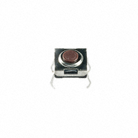
Actual Size
N KK Switches • email: sales@nkkswitches.com • Phone (480) 991-0942 • Fax (480) 998-1435 • www.nkkswitches.com
03-07
�6mm Process Sealed Tactiles
Series CB
General Specifications
Electrical Capacity (Resistive Load)
Low Level: 50mA @ 24V DC maximum
Other Ratings
Contact Resistance: Insulation Resistance: Dielectric Strength: Mechanical Life: Electrical Life: Nominal Operating Force: Total Travel: 100 milliohms maximum 100 megohms minimum @ 250V DC 250V AC minimum between contacts & between contacts & case for 1 minute minimum 100,000 operations minimum 100,000 operations minimum 1.57N .010” (.250mm)
Materials & Finishes
Actuator: Case: Seal: Base: Movable Contacts: Stationary Contacts: Terminals: Glass fiber reinforced polyamide (UL94V-0) Stainless steel Polytetrafluoroethylene Polyphthalamide (UL94V-0) Beryllium copper with silver plating Brass with silver plating Brass with silver plating
Environmental Data
Operating Temperature Range: Humidity: Vibration: Shock: –25°C through +70°C (–13°F through +158°F) 90 ~ 95% humidity for 96 hours @ 40°C (104°F) 10 ~ 55Hz with peak-to-peak amplitude of 1.5mm traversing the frequency range & returning in 1 minute; 3 right angled directions for 2 hours 50G (490m/s2) acceleration (tested in 6 right angled directions, with 5 shocks in each direction)
PCB Processing
Soldering: Cleaning: Wave Soldering Recommended. See Profile A in Supplement section. Manual Soldering: See Profile A in Supplement section. Automated cleaning. See Cleaning specifications in Supplement section.
Standards & Certifications
Flammability Standards: UL Recognition or CSA Certification: UL94V-0 actuator & base The CB Series tactiles have not been tested for UL recognition or CSA certification. These switches are designed for use in a low-voltage, low-current, logic-level circuit. When used as intended in a logic-level circuit, the results do not produce hazardous energy.
N KK Switches • email: sales@nkkswitches.com • Phone (480) 991-0942 • Fax (480) 998-1435 • www.nkkswitches.com
03-07
�6mm Process Sealed Tactiles
TYPICAL SWITCH ORDERING EXAMPLE
Series CB
CB
15
F
P
POLE & CIRCUIT
15 SPST OFF (ON) F ( ) = Momentary
ACTUATOR
Flat Button P
TERMINALS
Straight PC S No Code
PACKAGING
Stick-Tube 50 Pieces/Tube Partitioned Tray
DESCRIPTION FOR TYPICAL ORDERING EXAMPLE
CB15FP
Flat Button Straight PC Terminals SPST OFF-(ON) Circuit
POLE & CIRCUIT
Actuator Position ( ) = Momentary Normal Pole SP Model CB15 OFF (ON) Down
1 3 4
Switch Throw & Schematic
SPST
2
Note: Terminal numbers are not actually on the switch.
TYPICAL SWITCH DIMENSIONS
Single Pole • Single Throw
(3.0) Dia .118 (6.2) .244 (4.35) Dia .171 (0.65) .026 (3.1) .122 (0.3) Typ .012 (6.5) .256
2 4
1
3
3
1
4
2
(6.5) .256 (1.0) Dia Typ .039
(0.7) Typ .028
(6.2) .244
(3.5) .138
(4.0) .157
(4.0) .157
CB15FP
N KK Switches • email: sales@nkkswitches.com • Phone (480) 991-0942 • Fax (480) 998-1435 • www.nkkswitches.com
03-07
�6mm Process Sealed Tactiles
PACKAGING S
Stick-Tube
Switches must be ordered in 50-piece increments when stick-tube packaging is selected.
Series CB
No Code
Partitioned Tray
If ordered in less than 50-piece increments, the switches are packaged in a partitioned tray.
Stick-Tube Dimensions
(12.0) .472 (340.0) 13.386
Each stick-tube contains 50 switches
(11.0) .433
K EYBOARD MATRIX
Common Bus Matrix
5 1 2 9 3 13
X-Y Matrix
4 7 3 8
6 11 8 12
2 7 8
9
9 6
A 1 2
0
B
A
0
B 7
= ON
5 4 3
7
Blue = PCB Trace, Black = Switch Circuit These single pole, single throw switches can be used in a keyboard matrix and, using strapped terminals, achieve a common bus electrical configuration on a single-sided PC board.
Blue = PCB Trace, Black = Switch Circuit These single pole, single throw switches can be arranged on a single-sided PC board matrix with strapped terminals to achieve an X-Y type electrical interconnection.
03-07
N KK Switches • email: sales@nkkswitches.com • Phone (480) 991-0942 • Fax (480) 998-1435 • www.nkkswitches.com
Keys (Switches)
4
5
6
10
1 2 3 4 5 6 7 8 9 0 A B
P C Te r m i n a t i o n s 1 2 3 4 5 6 7 8 9 10 11 12 13
1
2
3 1
4
5
6
P C Terminations 1 234 567 1 2 3 4 5 6 7 8 9 0 A B = ON
Keys (Switches)
�
很抱歉,暂时无法提供与“CB15FP-S”相匹配的价格&库存,您可以联系我们找货
免费人工找货- 国内价格 香港价格
- 1+22.057411+2.85300
- 10+18.5231010+2.39586
- 50+16.2125750+2.09701
- 100+15.30199100+1.97923
- 250+14.19887250+1.83655
- 500+13.44685500+1.73928
- 1000+12.767781000+1.65144
- 2500+11.980502500+1.54961
- 5000+11.464655000+1.48289