Series G
Toggles
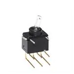
Fully Illuminated Ultra-Miniature Toggles
A
Rockers
General Specifications
Electrical Capacity (Resistive Load)
Logic Level: 0.4VA maximum @ 28V AC/DC maximum (Applicable Range 0.1mA ~ 0.1A @ 20mV ~ 28V) Note: Find additional explanation of operating range in Supplement section.
Programmable Illuminated PB
Pushbuttons
Other Ratings
Contact Resistance: Insulation Resistance: Dielectric Strength: Mechanical Life: Electrical Life:
Keylocks
Nominal Operating Force: Angle of Throw:
80 milliohms maximum 500 megohms minimum @ 500V DC 500V AC minimum for 1 minute minimum 100,000 operations minimum 100,000 operations minimum 10,000 operations minimum @ 0.1A @ 28V AC/DC 1.30N 28°
Materials & Finishes
Rotaries
Actuator: Case: Sealing Rings: Movable Contacts: Stationary Contacts: Base: Power Terminals: Lamp Terminals:
Polyamide Glass fiber reinforced polyamide Nitrile butadiene rubber Phosphor bronze with gold plating Phosphor bronze with gold plating Glass fiber reinforced polyamide Phosphor bronze with gold plating Phosphor bronze with gold plating
Tactiles
Slides
Environmental Data
Operating Temperature Range: Humidity: Vibration: Shock:
–25°C through +55°C (–13°F through +131°F) 90 ~ 95% humidity for 240 hours @ 40°C (104°F) 10 ~ 500Hz with peak-to-peak amplitude of 1.5mm traversing the frequency range & returning in 1 minute; 3 right angled directions for 2 hours 50G (490m/s2) acceleration (tested in 6 right angled directions, with 5 shocks in each direction)
Tilt
Touch
PCB Processing
Soldering: Cleaning:
Wave Soldering recommended. See Profile A in Supplement section. Manual Soldering: See Profile A in Supplement section. Automated cleaning. See Cleaning specifications in Supplement section.
Indicators
Standards & Certifications
Supplement
Accessories
The G Series toggles have not been tested for UL recognition or CSA certification. These switches are designed for use in a low-voltage, low-current, logic-level circuit. When used as intended in a logic-level circuit, the results do not produce hazardous energy.
A38
www.nkk.com
�Fully Illuminated Ultra-Miniature Toggles
Series G
A
Toggles Supplement Accessories Indicators Touch Tilt Tactiles Slides Rotaries Keylocks Programmable Illuminated PB Pushbuttons Rockers
Distinctive Characteristics
Fully illuminated toggle for highly visible status indication with LED in red, green, or amber for single color and red/green for bicolor. Ultra-miniature size allows high density mounting, and extremely light weight makes these switches ideal for handheld equipment. Totally sealed body construction prevents contact contamination and allows time- and money-saving automated soldering and cleaning. Molded-in, epoxy sealed terminals lock out flux, solvents, and other contaminants. Award-winning STC contact mechanism with benefits unavailable in conventional mechanisms: smooth, positive detent actuation, increased contact stability, and unparalleled logic-level reliability. (Additional STC details in Terms & Acronyms; see Supplement section.) .100” x .100” (2.54mm x 2.54mm) terminal spacing conforms to standard PC board grid spacing. Round terminals facilitate easier throughhole mounting on PC boards.
Actual Size
www.nkk.com
A39
�Series G
Toggles
Fully Illuminated Ultra-Miniature Toggles
TYPICAL SWITCH ORDERING EXAMPLE
A
Rockers
G
Pole
1 SPDT 2
1
Circuits
ON NONE ON
2
Actuator
J Clear
J
P H V
H
PC Terminals
Straight Right Angle Vertical C D F
C
LEDS
Single Color Red Amber Green Bicolor CF Red/Green ON-NONE-ON & ON-OFF-ON
Pushbuttons
Programmable Illuminated PB
Combines with single color or bicolor LEDs 3 ON OFF ON Combines with bicolor LED only SPDT ON-NONE-ON Circuit Clear Toggle, Red LED
ON-NONE-ON only
DESCRIPTION FOR TYPICAL ORDERING EXAMPLE
Keylocks
G12JHC
Right Angle PC Terminals
P OLES & CIRCUITS
Toggle Position Up Pole Throw Model G12 G13
Slot
Rotaries
Connected Terminals Up
Slot
Schematics Note: Terminal numbers are not actually on the switch. LED circuit is isolated and requires an external power source.
2 (COM) 3 1 (4) Red (5) (6) (5) (6) Green
Center
Down
Center
Down
Slides
SPDT
ON ON
NONE OFF
ON ON
2-3 2-3
NONE OPEN
2-1 2-1
Single Color
Bicolor
Tactiles
ACTUATOR J
28°
Clear Toggle
(3.8) .150
(1.7) Dia .067 (4.0) Dia .157
Tilt
Touch
LED COLORS & SPECIFICATIONS
Single Color LEDs are an integral part of the switch and not available separately. The electrical specifications shown are determined at a basic temperature of 25°C. If the source voltage exceeds the rated voltage, a ballast resistor is required. The resistor value can be calculated by using the formula in the Supplement; see Supplement Index. Bicolor
Indicators
C
Colors Forward Peak Current Continuous Forward Current Forward Voltage Reverse Peak Voltage I FM IF VF VRM Red 25mA 20mA 2.0V 4V
D
Amber 25mA 20mA 2.1V 4V
F
Green 25mA 20mA 2.1V 4V 0.33mA/°C –25° ~ +55°C
CF
Red/Green 25mA/25mA 20mA/20mA 2.0V/2.1V 4V/4V
Accessories
Supplement
Current Reduction Rate Above 25°C ∆I F Ambient Temperature Range
A40
www.nkk.com
�Fully Illuminated Ultra-Miniature Toggles
PC TERMINALS P
Straight
(2.54) Typ .100 (0.4) Dia Typ .016 (2.54) Typ .100 (2.6) .102
Series G
A
V
Vertical
(2.54) Typ .100 (0.4) Dia Typ .016
(7.0) .276
(4.5) .177
(7.0) .276
TYPICAL SWITCH DIMENSIONS
Straight PC
(1.7) Dia .067 (4.0) Dia .157 (0.4) Dia Typ .016
1 2 3 4 5 6
(2.54) .100 (7.0) .276 (0.6) Dia Typ .024 (2.54) .100
4 5 6
1 2 3
28°
(2.54) Typ .100
Slot (4.5) .177 (3.8) .150
(1.6) .063 (7.0) .276
(2.54) Typ .100 (2.6) .102
5 & 6 are LED terminals; 4 is a support pin on single color models & an LED terminal on bicolor models.
G12JPC
Right Angle PC
28°
Slot
(1.7) Dia .067
(4.0) Dia .157
3
2
1
(0.4) .016 (4.9) .193
4
5
6
(2.54) .100 (5.08) .200
(2.6) .102 (0.4) Dia Typ .016 (5.08) .200 (7.8) .307 (3.8) .150 (5.08) .200 (1.6) .063 (10.22) .402 (0.5) .020 (2.54) .100
6
5
4
(0.6) Dia Typ .024 (0.4) Dia Typ .016 (2.54) Typ .100
(7.0) .276
Vertical PC
(1.7) Dia .067 (4.0) Dia .157
1 2 3 4 5 6
(0.4) .016 (7.4) .292
4 5 6
1 2 3
28° (2.6) .102 (1.0) .039 (5.08) .200 (12.76) .502 (0.5) Typ .020 (2.54) Typ .100
(2.54) Typ .100 (5.08) .200
(0.4) Dia Typ .016 (2.54) .100 (5.3) .209
(1.6) .063 (3.8) .150
(0.4) Dia Typ .016 (2.54) .100 (4.5) .177
5 & 6 are LED terminals; 4 is a support pin on single color models & an LED terminal on bicolor models.
www.nkk.com
G12JVCF
A41
Supplement
Accessories
Slot
(0.6) Dia Typ .024
Indicators
(2.54) .100
Touch
5 & 6 are LED terminals; 4 is a support pin on single color models & an LED terminal on bicolor models.
G12JHD
Tilt
Tactiles
(2.54) Typ .100 1
2
3
Slides
Rotaries
Keylocks
Programmable Illuminated PB
(4.5) .177 (2.54) Typ .100
(7.0) .276
(4.5) .177
Pushbuttons
(0.5) Typ .020 (0.4) Dia Typ .016 (2.54) Typ .100
(2.54) Typ .100 (0.5) Typ .020
Rockers
H
Right Angle
Toggles
�
很抱歉,暂时无法提供与“G12JHCF”相匹配的价格&库存,您可以联系我们找货
免费人工找货- 国内价格 香港价格
- 1+100.941091+12.93470
- 10+87.1156610+11.16310
- 25+82.1415125+10.52570
- 50+78.5636850+10.06724
- 100+75.13495100+9.62787
- 250+70.82353250+9.07541
- 500+67.72074500+8.67781
- 1000+64.747521000+8.29682