Toggles
Series HB2
Rockers
General Specifications
Electrical Capacity (Resistive Load)
Slides
Rotaries
Keylocks
Programmable Illuminated PB
Pushbuttons
Logic Level (gold): 0.4VA maximum @ 28V AC/DC maximum
(Applicable Range 0.1mA ~ 0.1A @ 20mV ~ 28V)
Note: Find additional explanation of operating range in Supplement section.
Other Ratings
Contact Resistance:
Insulation Resistance:
Dielectric Strength:
Mechanical Life:
Electrical Life:
Nominal Operating Force:
Travel:
D
Materials & Finishes
Housing:
Base:
Movable Contact:
Switch Terminals:
Lamp Terminals:
Environmental Data
Operating Temperature Range:
Humidity:
Vibration:
Tactiles
Shock:
Installation
Cap Installation Force:
Tilt
PCB Processing
Soldering:
Cleaning:
Standards & Certifications
80 milliohms maximum
500 megohms minimum @ 500V DC
500V AC minimum for 1 minute minimum
100,000 operations minimum for momentary;
100,000 operations minimum
1.8N
Pretravel .051” (1.3mm); Overtravel .020” (0.5mm); Total Travel .071” (1.8mm)
Glass fiber reinforced polyamide
Glass fiber reinforced polyamide
Phosphor bronze with gold plating
Brass with gold plating
Steel with silver plating
–25°C through +50°C (–13°F through +122°F)
90 ~ 95% humidity for 240 hours @ 40°C (104°F)
10 ~ 55Hz with peak-to-peak amplitude of 1.5mm traversing the frequency range & returning
in 1 minute; 3 right angled directions for 2 hours
50G (490m/s2) acceleration (tested in 6 right angled directions, with 5 shocks in each direction)
15.0N (3.37 lbf) maximum downward force on cap
Wave Soldering: See Profile A in Supplement section.
Manual Soldering: See Profile B in Supplement section.
These devices are not process sealed. Hand clean locally using alcohol based solution.
The HB2 pushbuttons have not been tested for UL recognition or CSA certification.
These switches are designed for use in a low-voltage, low-current, logic-level circuit.
When used as intended in a logic-level circuit, the results do not produce hazardous energy.
Supplement
Accessories
Indicators
Touch
Subminiature Audio/Video Pushbuttons
D18
www.nkkswitches.com
10/24/19
�Toggles
Series HB2
Rockers
Distinctive Characteristics
Pushbuttons
Quiet actuation combined with crisp tactile feedback suited for broadcast equipment.
Full face illumination with choice of red/green or red/yellow
bicolor LEDs, as well as simultaneous bicolor illumination
which produces amber.
D
Option of legends on caps or film insert.
Keylocks
Compact design with short body .669” (17.0mm) from
PCB to top of cap and .295” (7.5mm) square cap.
Programmable Illuminated PB
Subminiature Audio/Video Pushbuttons
Rotaries
Sliding Twin Crossbar (STC) mechanism provides
unequalled logic-level reliability, contact stability,
smooth positive detent actuation, and long life.
Slides
Crimped power terminals ensure secure PCB mounting
and prevent dislodging during soldering.
Touch
Tilt
Tactiles
Suitable applications include broadcast, telecommunication,
and medical equipment, as well as measuring instruments, etc.
Supplement
Accessories
Indicators
Actual Size
www.nkkswitches.com
D19
�Series HB2
Toggles
Subminiature Audio/Video Pushbuttons
TYPICAL SWITCH ORDERING EXAMPLE
Rockers
Pushbuttons
5
Pole
1
S
K
Shape
S
SPST
D
OFF
Square
JB
Cap Colors
Gold Contacts and
PC Terminals, Rated
0.4VA @ 28V AC/DC
G03
(ON)
K
LEDs
Black
CE
Red/Yellow
CF
Red/Green
Amber can be achieved
by simultaneous
illumination of LEDs.
DESCRIPTION FOR TYPICAL ORDERING EXAMPLE
HB215SKG03CF-JB
Red/Green LED
Clear Lens/
White Diffuser
JB
Housing
( ) = Momentary
Clear Lens
with White Diffuser
Black Housing
SPST
OFF–(ON) Circuit
Rotaries
CF
Contacts & Terminals
Square Shape
Gold Contacts & PC Terminals with
0.4VA @ 28V AC/DC Rating
POLE & CIRCUIT
Slides
Tactiles
G03
Circuit
5
Keylocks
Programmable Illuminated PB
1
HB2
Plunger Position
( ) = Momentary
Normal
Pole
Down
Connected Terminals
Normal
Down
Model
Throw & Switch/Lamp Schematics
Notes:
Switch terminals are not marked on the switch.
Red LED terminal is marked with “R”.
Lamp circuit is isolated and requires
external power source.
Red
Tilt
3 (+)
HB215
SP
OFF
(ON)
OPEN
1-2
4 (-)
SPST
1
2
5 (+)
Yellow or Green
Touch
HOUSING SHAPE & COLOR
S
K
Indicators
.307” (7.8mm) Square Body
Black Housing
CONTACT MATERIALS, RATINGS & TERMINALS
Accessories
G03
CL
Gold Contacts
Logic Level
Supplement
Switch Terminal
(0.4)
.016
(0.5) Sq
.020
D20
(3.5)
.138
0.4VA maximum @ 28V AC/DC maximum
Lamp Terminal
(0.4)
.016
(0.5) Sq
.020
www.nkkswitches.com
(3.5)
.138
PCB Footprint
(0.5)
.020
(2.5) Typ
.098
(5.0)
.197
(1.0) Dia
.039
(0.85) Dia Typ
.033
(2.25) Typ
.089
(1.0) Dia
.039
3
4
5
(4.5)
.177
1
2
(0.92)
.036
(2.54)
.100
�Series HB2
Toggles
Subminiature Audio/Video Pushbuttons
IF
Anode
Color
VF
E
Cathode
–
R =
Where: R =
E =
VF =
IF =
E – VF
IF
Resistor Value (Ohms)
Source Voltage (V)
Forward Voltage (V)
Forward Current (A)
CE
CF
Red/Yellow
Red/Green
LED is an integral part of the switch.
Red
Yellow
Red
Green
Maximum Forward Current
IFM
* 30mA
* 25mA
* 30mA
* 25mA
Typical Forward Current
IF
20mA
20mA
20mA
20mA
Forward Voltage
VF
2.0V
2.2V
2.0V
2.25V
Maximum Reverse Voltage
VRM
5V
5V
5V
5V
Current Reduction Rate Above 25°C
∆IF
0.40mA/°C
0.33mA/°C
0.40mA/°C
0.33mA/°C
Ambient Temperature Range
Pushbuttons
+
–25° ~ +50°C
The electrical specifications shown are determined at a basic temperature of 25°C. LED circuit is isolated and requires an external
power source. If the source voltage exceeds the rated voltage, a ballast resistor is required. The resistor value can be calculated by
using the formula in the Supplement section.
* Value applies to single color illumination for either Red or Yellow or Red or Green. When both colors are illuminated simultaneously,
the sum of the currents should not exceed the smallest value of the maximum forward current.
(3.5)
.138
Clear Transparent Lens
AT3081
Square Lens
B
AT3082
Square Diffuser
(7.5) Sq
.295
Lens & Diffuser Material: Polycarbonate
(1.0)
.039
White Translucent Diffuser
Lens Finish: Glossy
Rotaries
J
Keylocks
CAP COLORS
(5.8) Sq
.228
Diffuser Finish: Frosted
Slides
TYPICAL SWITCH DIMENSIONS
Single Pole
(0.8) Dia Typ
.031
(2.54)
.100
3
(7.5) Sq
.295
(0.5) Sq Typ
.020
2
(0.4)
.016
(3.5)
.138
(5.0)
.197
5
(4.5)
.177
(7.8) Sq
.307
(11.7)
.461
(3.1)
.122
(0.5)
.020
HB215SKG03CF-JB
Touch
(17.0)
.669
R
4
1
(0.92)
.036
Square
(0.5) Sq Typ
.020
Tactiles
(1.4)
.055
Tilt
D
Programmable Illuminated PB
R
Rockers
BICOLOR LEDS & SPECIFICATIONS
LEGENDS
Suggested Printable Area for HB2 Lens & Film Insert
Lens
Recommended Methods: Screen Print or Pad Print on Lens; Laser Print on Film Insert.
Epoxy based ink is recommended. Film Insert: Clear Polyester, 4 mil max. thickness
(0.6) R
.024
Lens
Shaded areas are printable areas.
Film Insert
Diffuser
(5.98) Sq
.235
(7.5) Sq
.295
(0.76) Typ
.030
(5.7) Sq
.224
www.nkkswitches.com
Supplement
UP
Film
Insert
Accessories
Indicators
NKK Switches can provide custom legends for caps. Contact factory for more information.
(4.17) Sq
.164
(0.76) Typ
.030
D21
�
很抱歉,暂时无法提供与“HB215SKG03CE-JB”相匹配的价格&库存,您可以联系我们找货
免费人工找货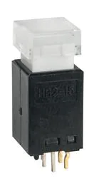


 工商网监
湘ICP备2023018690号
工商网监
湘ICP备2023018690号
