Toggles
Series HS TS PS
GENERAL SPECIFICATIONS
Rockers
Electrical Capacity
Pushbuttons
Resistive Load:
Other Ratings
Materials & Finishes
Knob:
Shaft:
Bushing:
Case:
Movable Contacts:
Stationary Contacts:
Terminals:
Environmental Data
Installation
Indicators
Tilt
G
Touch
Tactiles
Slides
Rotaries
Keylocks
Programmable Illuminated PB
Contact Resistance:
Insulation Resistance:
Dielectric Strength:
Mechanical Life:
Electrical Life:
Indexing:
Contact Timing:
Range of Operating Torque:
Operating Temp Range:
Humidity:
Vibration:
Shock:
HS13: 6A @ 125V AC, 3A @ 250V AC, or 5A @ 30V DC
HS16: 12A @ 125V AC or 6A @ 250V AC
TS: 6A @ 125/250V AC
PS: 30A @ 125/250V AC
10 milliohms maximum
200 megohms minimum @ 500V DC
1,500V AC minimum for 1 minute minimum
HS: 15,000 operations minimum
TS: 30,000 operations minimum
PS: 10,000 operations minimum
HS: 7,500 operations minimum
TS: 10,000 operations minimum
PS: 5,000 operations minimum
30° for HS16, TS & PS; 45° for HS13
Nonshorting HS13; Shorting & Nonshorting HS16; Nonshorting TS; Nonshorting PS
HS16: 0.54 ~ 0.64Nm for first pole & 0.05Nm for each additional pole
HS13: 0.15 ~ 0.24Nm
TS: 0.09Nm for first pole & (0.07Nm x total number of poles) + 0.13Nm for additional poles
PS: 0.14Nm for each pole
Phenolic resin
HS13: brass; HS16, TS, & PS: brass with nickel plating
HS13: brass; HS16, TS, & PS: brass with nickel plating
Phenolic resin
HS13, HS16, & TS phosphor bronze; PS silver alloy
HS13, HS16, & PS: brass with silver plating; TS: phosphor bronze
HS: phosphor bronze; TS & PS: copper with silver plating
–10°C through +70°C (+14°F through +158°F)
90 ~ 98% humidity for 96 hours @ 40°C (104°F)
10 ~ 55 Hz with peak-to-peak amplitude of 1.5mm traversing the frequency range
& returning in 1 minute; 3 right angled directions for 2 hours
50G (490m/s2) acceleration (tested in 3 right angled directions, with 3 shocks in each direction)
Mounting Torque: 2.94Nm (26 lb•in)
Maximum Panel Thickness: Shown with panel cutouts in following drawings
Soldering Time & Temperature: Manual Soldering (HS series only): See Profile A in Supplement section.
Standards & Certifications
UL: File No. E44145 - Recognized only when ordered with marking on switch.
Add “/U” or “/CUL” to end of part number to order UL recognized switch.
HS16 models 1– through 6–pole are recognized at 12A @ 125V AC & 6A @ 250V AC
See Supplement section to find UL or cULus rating details.
Supplement
Accessories
Standard Size Rotaries
G46
www.nkkswitches.com
�Toggles
Series HS
Standard Size Rotaries
6 AMP SINGLE POLE/NONSHORTING/45° INDEXING
Stopper
Settings
Number of
Terminals
Load
Terminals
HS13X
HS13X-D
2
Fixed
1 COM, 2 LOAD
1&2
HS13Y
HS13Y-D
3
Fixed
1 COM, 3 LOAD
1, 2, & 3
HS13Z
HS13Z-D
4
Fixed
1 COM, 4 LOAD
1, 2, 3, & 4
Schematics
HS13X
CL of Keyway
HS13Y
2
HS13Z
CL of Keyway
3
2
CL of Keyway
3
4
2
1
1
1
C1
C1
C1
Rockers
Number of
Positions
Pushbuttons
D-flat
Shaft
Switch is viewed from shaft end and shown in position 1. Terminal numbers are not on switch. Standard Hardware shown on last page of this section.
45° T
yp
4
(6.0) Dia
.236
(5.7) Typ
.224
(0.3)
.012
(10.0) (10.0) (16.0)
.394 .394 .630
(40.0)
1.575
(34.0) Dia
1.339
(9.5)
.374
(9.0)
.354
2
(1.5)
.059
(3.0) Dia
.118
1
(4.8) Typ
.189
(10.3) Dia
.406
(10.5) Dia
.413
3
Maximum Effective Panel Thickness
With Locking Ring
.150” (3.8mm)
Without Locking Ring
.189” (4.8mm)
COM
(2.6) Dia Typ
.102
Programmable Illuminated PB
(0.7) Typ
.028
M10 P0.75
Keyway
HS13X
D-flat Shaft
Shorting
Nonshorting
Shorting
Pole
Number of
Positions
Stopper
Settings
Number of
Terminals
HS16-1
HS16-1S
HS16-1N
HS16-1SN
1P
2-11
2, 3, 4 . . . 11
1 COM, 11 LOAD
Schematic
HS16-2
HS16-2S
HS16-2N
HS16-2SN
2P
2-11
2, 3, 4 . . . 11
2 COM, 22 LOAD
HS16-3
HS16-3S
HS16-3N
HS16-3SN
3P
2-11
2, 3, 4 . . . 11
3 COM, 33 LOAD
HS16-4
HS16-4S
HS16-4N
HS16-4SN
4P
2-11
2, 3, 4 . . . 11
4 COM, 44 LOAD
HS16-5
HS16-5S
HS16-5N
HS16-5SN
5P
2-11
2, 3, 4 . . . 11
5 COM, 55 LOAD
HS16-6
HS16-6S
HS16-6N
HS16-6SN
6P
2-11
2, 3, 4 . . . 11
6 COM, 66 LOAD
C1
1
11
G
2
3
10
CL of Keyway
4
9
5
8
7
Slides
Knurled Shaft
Nonshorting
Keylocks
12 AMP/SHORTING & NONSHORTING/30° INDEXING
Rotaries
Round
Shaft
6
Switch is viewed from shaft end and shown in position 1. Terminal numbers are not on switch. Standard Hardware shown on last page of this section.
30
Tactiles
15°
°
Keyway
1
3
4
9
6
(55.0)
2.165
(1.5)
.059
Maximum Effective Panel Thickness
With Locking Ring
.189” (4.8mm)
Without Locking Ring
.228” (5.8mm)
(14.0)
.551
(0.84) Typ
.033
(54.5)
2.146
(74.5)
2.933
(64.5)
2.539
(2.6) Dia Typ
.102
(6.24) Typ
.246
(7.0) Max
.276
• On each deck of multipole devices common and load terminals
are in the same positions as shown in the schematic above.
Accessories
(3.0) Dia
.118
(9.5)
.374
(15.0)
.591
(44.5)
1.752
• Switch is viewed from the shaft end and shown in position 1.
• Terminal numbers are on the switch bottom. Stopper positions
are molded on the top of the switch.
• Standard Hardware shown on last page of this section.
www.nkkswitches.com
Supplement
(9.0)
.354
(10.3) Dia
.406
(34.5)
1.358
Touch
(24.5)
.965
Indicators
(10.0)
.394
(8.0) Typ
.315
7
(4.4)
.173
(10.5) Dia
.413
8
5
10
(65.0)
2.559
11
2
COM
Tilt
M10 P0.75
(6.0) Dia
.236
HS16-2N
G47
�Toggles
Series TS
Standard Size Rotaries
Rockers
6 AMP/NONSHORTING/ADJUSTABLE STOP/30° INDEXING
Model
Pole
Number of
Positions
Stopper
Settings
Number of
Terminals
Shaft
Type
TS1N
1P
2-11
2, 3, 4 . . . 11
1 COM, 11 LOAD
D Flat
Schematic
CL of Keyway
C1
1
2
Pushbuttons
11
TS2N
2-11
2, 3, 4 . . . 11
2 COM, 22 LOAD
10
3
9
4
D Flat
5
Keylocks
Programmable Illuminated PB
8
TS3N
3P
2-11
2, 3, 4 . . . 11
3 COM, 33 LOAD
D Flat
TS4N
4P
2-11
2, 3, 4 . . . 11
4 COM, 44 LOAD
D Flat
TS5N
5P
2-11
2, 3, 4 . . . 11
5 COM, 55 LOAD
D Flat
6
7
On each deck of multipole devices common
& load terminals are in the same positions
as shown in this schematic.
Switch is viewed from the shaft end and
shown in position 1.
Terminal numbers are on the switch bottom.
Stopper positions are molded on the top of
the switch.
• Standard Hardware shown on last page of this section.
Top
Panel Cutouts
15°
Keyway
3
4
2
3
5
4
6
5
6
(42.0) Dia
1.654
(44.0) Dia
1.732
Touch
M3 x 4 Typ
Indicators
M10 P0.75
Accessories
Supplement
(6.0) Dia
.236
(13.0)
.512
(15.6)
.614
TS5N
www.nkkswitches.com
7
Slides
1
9
7
Maximum Effective Panel Thickness
With Locking Ring
.189” (4.8mm)
Without Locking Ring
.228” (5.8mm)
G48
COM
10
(4.4)
.173
8
Tactiles
1
2
9
(1.5)
.059
(3.0) Dia
.118
Tilt
15°
1
(9.5)
.374
10
(9.0)
.354
°
30
(10.3) Dia
.406
11
(10.5) Dia
.413
Bottom
8
G
1
Rotaries
2P
(22.0)
.866
(14.0)
.551
(34.0)
1.339
(46.0)
1.811
(58.0)
2.283
(70.0)
2.756
�Toggles
Series PS
Standard Size Rotaries
30 AMP/NONSHORTING/ADJUSTABLE STOP/30° INDEXING
Knurled
Shaft
D Flat
Shaft
Pole
Number of
Positions
Stopper
Settings
Number of
Terminals
PS1
PS1N
1P
2-11
2, 3, 4 . . . 11
1 COM, 11 LOAD
Rockers
Schematic
CL of Keyway
C1
1
PS2
PS2N
2P
2-11
2, 3, 4 . . . 11
2 COM, 22 LOAD
PS3
PS3N
3P
2-11
2, 3, 4 . . . 11
3 COM, 33 LOAD
10
3
PS4
PS4N
4P
2-11
2, 3, 4 . . . 11
4 COM, 44 LOAD
9
4
PS5
PS5N
5P
2-11
2, 3, 4 . . . 11
5 COM, 55 LOAD
Pushbuttons
2
11
7
Programmable Illuminated PB
5
8
6
On each deck of multipole devices common & load terminals are in the same positions as shown in this schematic. Switch is viewed from
the shaft end and shown in position 1. Terminal numbers are on switch bottom. Stopper positions are molded on the top of the switch.
• Standard Hardware shown on last page of this section.
Top
Bottom
(10.5) Dia
.413
10
15°
11
COM
4
3
120°Typ
G
1
6
2
10
(3.0) Dia
.118
2
4
3
(40.0) Dia
1.575
Maximum Effective Panel Thickness
Without Locking Ring
.189” (4.8mm)
Slides
11
5
M4
(76.0) Dia
2.992
Tactiles
(20.0) R
.787
8
(9.0)
.354
7
° Typ
120
7
9
8
6
30
° Ty
p
(4.5) Dia Typ
.177
Keylocks
(4.4)
.173
Rotaries
Panel Cutout
(70.0) Dia
2.756
Tilt
M4 x 5 Typ
M10 P0.75
Touch
Keyway
Indicators
(6.0) Dia
.236
(15.0)
.591
(29.0)
1.142
(24.5)
.965
(42.0)
1.654
(59.5)
2.343
(77.0)
3.031
(94.5)
3.720
(15.0) Max
.591
www.nkkswitches.com
Supplement
(7.0)
.276
Accessories
(10.0)
.394
PS4N
G49
�Series HS TS PS
Toggles
Standard Size Rotaries
SHAFT TYPES
Rockers
D Flat Shaft
Dim A
(6.0) Dia
.236
(4.4)
.173
Pushbuttons
For use with
AT431 and AT432
Knurled Shaft
Dimension B
For TS (15.6)
.614
For HS (15.0)
or PS .591
(6.0) Dia
.236
Not for use with
AT431 or AT432
(20.0)
.787
Programmable Illuminated PB
OPTIONAL KNOBS FOR D FLAT SHAFTS
AT431
Large Knob
AT432
Small Knob
Phenolic Resin
Phenolic Resin
(19.5)
.768
Black only
with white
indicator
(24.0)
line
.945
Keylocks
Rotaries
Dim B
Dimension A
For TS (13.0)
.512
For HS (10.0)
or PS .394
(30.0) Dia
1.181
(15.6)
.614
(21.0)
.827
(25.0) Dia
.984
(5.5)
.217
(5.5)
.217
(24.0)
.945
(9.0)
.354
G
(57.0)
2.244
Black only
with white
indicator
line
Knob Orientation
(29.0)
1.142
(21.0)
.827
(9.0)
.354
(21.0)
.827
(28.0)
1.102
(20.0)
.787
M2.3 x 0.4 x 8.0
Assembly Screw
Set Screw
Adaptor
Shaft
Slides
M2.3 x 0.4 x 8.0
(41.0)
1.614
The rotary
knobs used
on the D-flat
shafts can
be oriented
on the switch
to suit the
customer’s
particular
front panel
needs simply
by sliding the
knob over
the square
adaptor at
the preferred
orientation.
Tactiles
AT526
The HS16, TS, and PS switches are supplied with the stopper plate set for the
maximum number of positions allowed for that model. Prior to installation,
the desired stopper setting should be made:
AT518
AT526
2. Loosen the nut far enough to allow raising the stopper plate for resetting.
3. Insert the stopper in the numbered hole for the desired stopper setting.
Satisfactory switch functioning cannot be assured if the stopper plate is
not properly positioned.
Supplement
G50
www.nkkswitches.com
5
4
3
11
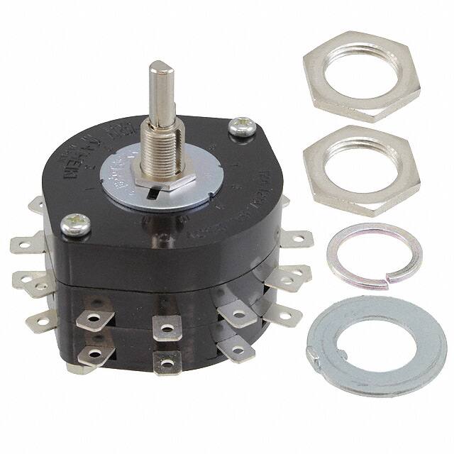
AT526 Hex Mounting Nut (quantity 3)
AT518 Locking Ring (quantity 1)
AT520 Split Lockwasher (quantity 1)
Use of mounting supports on PS is optional; screws are not provided.
10
Standard Hardware Supplied with HS, TS, and PS:
6
7
4. Tighten the nut firmly against the stopped plate.
2
Indicators
AT526
1. Be sure the shaft is turned counterclockwise to the extreme left. If the
shaft is not turned counterclockwise to the extreme left, proper setting
cannot be achieved.
9
Accessories
AT520
1
Touch
For HS16, TS, & PS Models
Tilt
STOPPER SETTING
�


 工商网监
湘ICP备2023018690号
工商网监
湘ICP备2023018690号
