Toggles
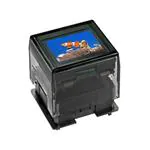
LCD 36 x 24 Pushbuttons & Display
DISTINCTIVE CHARACTERISTICS
Standard with Enhanced LED Illumination:
Rockers
• Broad and even light diffusion
• Consistent backlighting
Programmable LCD
Variety of LED Backlighting Colors
Rubber Dome
Epoxy Sealed Straight PC Terminals
E
Keylocks
RGB or bicolor red/green backlighting provides infinite color
availability.
Programmable to display graphics, alphanumeric characters
and animated sequences.
Rotaries
Integrated liquid crystal display provides wide viewing angle
with high contrast and clarity.
Viewing area for switches 17.0mm x 13.0mm
(horizontal x vertical) at 36 x 24 pixels;
Display viewing area 14.4mm x 11.8mm.
Slides
Actual Sizes
Tactiles
Dome gives crisp tactile feedback to positively indicate circuit
transfer.
High reliability and long life of one million actuations minimum.
Display
Touch
Switch
Tilt
Epoxy sealed terminals prevent entry of solder flux and other
contaminants.
Optional accessories available to enhance panel design and
simplify production process.
Programmable Illuminated PB
Pushbuttons
• Low energy consumption
Switch Description
LCD Mode
LED Color
IS15BBFP4RGB
SPST
Momentary ON
Gold Contacts
Straight PC Terminals
Black & White
FSTN Positive
* Red/Green/Blue
IS15BAFP4CF
SPST
Momentary ON
Gold Contacts
Straight PC Terminals
Black & White
FSTN Positive
* Red/Green
Supplement
Accessories
Part Number
Indicators
PART NUMBERS & DESCRIPTIONS
* Simultaneous illumination of LEDs achieves infinite colors.
www.nkkswitches.com
E35
10/03/19
�Toggles
LCD 36 x 24 Display
DISTINCTIVE CHARACTERISTICS
Rockers
Standard with Enhanced Illumination:
Standard SMARTDISPLAY TM can be used alone or in
conjunction with electromechanical switches.
Integrated liquid crystal display provides wide viewing
angle with high contrast and clarity.
RGB LED provides numerous color variations.
Viewing area 14.4mm x 11.8mm (horizontal x vertical)
at 36 x 24 pixels.
E
Terminals
LCD Mode
LED Color
IS01BBFRGB
Straight PC
Black & White
FSTN Positive
* Red/Green/Blue
Rotaries
Part Number
Keylocks
PART NUMBER & DESCRIPTION
Programmable Illuminated PB
Pushbuttons
Programmable to display graphics, alphanumeric characters
and animated sequences.
* Simultaneous illumination of LED achieves infinite colors.
Slides
CHARACTERISTICS OF DISPLAY
14.4mm x 11.8mm (horizontal x vertical)
Pixel Size
0.371mm x 0.445mm (horizontal x vertical)
Backlight LED
RGB: red/green/blue
Tactiles
Viewing Area
TYPICAL DISPLAY DIMENSIONS FOR RGB LED
(10.0)
.394
(0.5) Sq Typ
.020
(8.6)
.339
(9.9)
.390
(17.8)
.701
(0.371)
.0146
(0.02) Typ
.0008
12
11
(2.0)
.079
(0.7) Typ
.028
(3.0)
.118
(14.7)
.579
Touch
1
(2.0) Typ (16.8)
.079
.661
(14.06)
.554
Pixel Detail
Key
2
(11.14)
.439
(11.8)
.465
(0.445)
.0175
(0.65) Typ
.026
(2.0) Typ
.079
Indicators
(12.2)
.480
(17.2)
.677
(10.0)
.394
(0.4) Typ
.016
(0.8) Dia
.031
(15.0)
.591
1
(10.0)
.394
Footprint
(2.0)
.079
www.nkkswitches.com
CL
2
(14.7)
.579
(2.0) Typ
.079
11
Accessories
(3.7)
.146
(14.4)
.567
12
(10.0)
.394
(15.0)
.591
(16.8)
.661
Supplement
See
Pixel Detail
Tilt
Terminal numbers are not on the device.
19x (0.9) Dia
.035
E39
�Toggles
LCD 36 x 24 Display
Pushbuttons
Programmable Illuminated PB
7
IS01BBFRGB
RGB LED Backlight
Black and White LCD
Timing Control
LP
5
Din
3
GND
Keylocks
E
FLM
SCP
Rotaries
BL-LED (+)
36 x 24 Dot Matrix
LCD Panel
seg1
seg36
Segment Driver
CK
40bit Latch
CK 40bit
D Shift Register Q
Red
10
Com24
6
9
Com1
4
Common Driver
1
VLC
VDD
D 24bit
CK Shift Register
Rockers
BLOCK DIAGRAM & PIN CONFIGURATIONS FOR RGB LEDS
Green
Dout
8
BL-LED (–)
2
BL-LED (–)
12
BL-LED (–)
Supplement
Accessories
Indicators
Touch
Tilt
Tactiles
Slides
Blue
11
Pin No. Symbol
Name
Function
1
VLC
2
BL-LED (–)
3
GND
Ground
4
VDD
Power
Power
Power source for LCD drive
Terminal of Backlight LED
Cathode for green
Power source for logic circuit
5
Din
Data Input
Display serial data bit. Note: to map the display data, because of the difference between the
number of internal shift register data (40) and the single line of LCD pixels (36), the first four
bits of data shifted will be dummy bits.
6
SCP
Serial Clock Pulse
Clock used by 40-bit internal shift register of the switch, shifting the display data bit presented
at Din at falling edge.
7
LP
Latch Pulse
Line data latch pulse will latch content of internal 40-bit shift register at falling edge for one
line of display. LP will also increment the display line by one.
8
BL-LED (–)
Terminal of Backlight LED
9
FLM
First Line Marker
10
BL-LED (+)
Terminal of Backlight LED
11
Dout
Data Output
E40
12
BL-LED (–)
Terminal of Backlight LED
Cathode for red
The marking signal for the first line data of LCD display. The first line of LCD will be selected
by the falling edge of LP signal during the high level (FLM).
Anode for common
Display serial output. Can be used to connect to Din of the next DISPLAY. As a result, many
DISPLAYS can be controlled with one clock and data signal.
Cathode for blue
www.nkkswitches.com
�Toggles
LCD 36 x 24 Pushbuttons, Display & Compacts
Absolute Maximum Ratings (Temperature at 25°C)
Ratings
VDD
–0.3V to +7.0V
Supply Voltage for LCD
VLC
–0.3V to +12.0V
Input Voltage
VI
–0.3V to VD D +0.3V
Output Voltage
VO
–0.3V to VD D +0.3V
Rockers
Supply Voltage for Logics
Pushbuttons
Symbols
LCD SPECIFICATIONS
Characteristics of Display
Display Operation Mode
FSTN positive
Display Condition
Transflective with built-in LED backlight
Viewing Angle
6 o’clock
Driving Method
1/24 duty. 1/5 bias (built-in driving circuit)
Pixel Format
36 x 24 pixels (horizontal x vertical)
Backlight LED
RGB: red/green/blue Bicolor: red/green
Keylocks
E
Minimum
Typical
Maximum
Supply Voltage for Logics
VDD
3.0V
––
5.5V
Supply Voltage
VLC
––
* 7.3V
––
VI
0V
––
VDD
Driving Frequency
f FLM
––
Clock Operation Frequency
f SCP
––
150Hz
––
––
8.0MHz
Tactiles
Input Voltage
Slides
Symbols
Rotaries
Recommended Operating Conditions (Temperature at 25°C)
Items
* LCD voltage (VL C ) level depends on refreshing frequency and temperature. The optimal VL C can differ slightly from the stated typical value.
Maximum
Unit
High Level Input Voltage
VIH
0.7VDD
VD D
V
Low Level Input Voltage
VI L
0
0.3VD D
V
High Level Input Leakage Current
ILI H
VI = VD D
10
μA
Low Level Input Leakage Current
ILIL
VI = 0V
10
μA
High Level Output Voltage
VOH
I O H = –500μA
Low Level Output Voltage
VOL
I O L = 500μA
0.5
V
High Level Output Leakage Current
I LO H
VO = VD D
10
μA
Low Level Output Leakage Current
I LO L
VO = 0V
10
μA
Supply Current
ID D
f S CP = 1.0MHz
500
μA
LCD Drive Current
I LC
f L P = 2.4kHz VLC = 7.3V
2,000
μA
www.nkkswitches.com
VDD –0.5
Touch
Typical
Indicators
Minimum
V
500
Accessories
Test Conditions
Supplement
Symbols
Tilt
DC Characteristics of LCD Drive (Temperature at –20°C to +60°C and VDD = 5.0V ±10%)
Items
Programmable Illuminated PB
Items
E45
�LCD 36 x 24 Pushbuttons, Display & Compacts
Toggles
Timing Characteristics of LCD Drive IC
(Temperature at –20°C to +60°C and VDD = 5.0V ±10%)
Keylocks
Programmable Illuminated PB
Pushbuttons
Rockers
Items
E
Symbols
Minimum
Maximum
Clock Operation Frequency
f SCP
8.0MHz
Latch Pulse Frequency
f LP
50kHz
Clock High Level Pulse Width
tC WH
50ns
Clock Low Level Pulse Width
tC WL
50ns
Data Setup Time
t DS D
45ns
Data Hold Time
tD H D
50ns
Data Output Delay Time
tPD O
Latch Setup Time
t DS L
50ns
Latch Hold Time
tD H L
50ns
Latch High Level Width
t LW H
50ns
FLM Setup Time
t DS F
50ns
FLM Hold Time
tD H F
50ns
SCP, LP Rise/Fall Time
t r/t f
25ns
15ns
tr
Timing Diagram
Rotaries
SCP
tCWH tCWL
tDSD
tf
tDHD
Din
*1 Last data on first line
*2 Beginning data on second line
*3 Location of LP signal on first line
*1
tPDO
Slides
Dout
tDSL
LP
tr
FLM
Tactiles
*2
*3
tLWH
tDSF
LED CHARACTERISTICS
tDHL
tf
tDHF
Red
Green
Blue
Red/Green
Unit
IF
10
8.5
8.0
15/15
mA
Symbols
Red
Green
Blue
Red/Green
Unit
Indicators
Backlight Color
Forward Current
IF
20
20
20
20
mA
Forward Voltage
VF
2.0
(I F = 10mA)
2.8
(I F = 8.5mA)
2.8
(I F = 8.0mA)
1.9/1.9
V
Reverse Voltage
VR
4.0
4.0
4.0
4.0
V
∆ I F (D C)
–0.33
–0.33
–0.33
–0.26
mA/°C
PD
40
60
60
130 maximum
mW
Tilt
Symbols
Accessories
Typical Electrical Characteristics (Temperature at 25°C)
Forward Current
Touch
ABSOLUTE MAXIMUM FOR LEDS
Electrical Characteristics (Temperature at 25°C)
Supplement
Backlight Color
Current Reduction Rate Above 25°C
*Power Dissipation
(LED Overall 115mW)
*For uniform light emission, Power Dissipation should not exceed the Absolute Maximum Rating, and the Forward Current should not exceed the
derated Absolute Forward Current.
E46
www.nkkswitches.com
�Toggles
LCD 36 x 24 Pushbuttons, Display & Compacts
PRECAUTIONS FOR HANDLING & STORAGE OF LCD 36 x 24 DEVICES
Handling
Rockers
ATTENTION
ELECTROSTATIC
SENSITIVE DEVICES
1. The IS Series devices are electrostatic sensitive.
Pushbuttons
2. Limit operating force to keytop to 100.0N maximum, as excessive pressure may damage the LCD device.
3. The IS series devices are not process sealed.
4. If the LCD is accidentally broken, avoid contact with the liquid and wash off any liquid spills to the skin or
clothing.
5. Clean cap surface with dry cloth. If further cleaning is needed, wipe with dampened cloth using neutral
cleanser and dry with clean cloth. Do not use organic solvent.
6. Recommended soldering time and temperature limits:
Do not exceed 70°C at the LCD level.
Wave Soldering: see Profile B in the Supplement section.
Manual Soldering for Switch: see Profile A in the Supplement section.
Manual Soldering for Display: see Profile B in the Supplement section.
Keylocks
E
Programmable Illuminated PB
7. Recommendation for backlight color uniformity: Use constant current driver. For current limiting resistor
method, the power source should be at least twice the backlight LED forward voltage.
Rotaries
8. The VLC voltage should not be applied before logic voltage. If VLC voltage is present before logic voltage,
it may cause the driver logic to freeze and damage the LCD, and the driver logic may become damaged.
9. Backlight Forward Current should not exceed the derated Absolute Maximum Forward Current based on
the temperature.
Slides
10. Excessive images may result after the same image is emitted continuously for an extended period of time.
Storage
Tactiles
1. Store in original container and away from direct sunlight.
2. Keep away from static electricity.
Supplement
Accessories
Indicators
Touch
Tilt
3. Avoid extreme temperatures, high humidity, gaseous substances, and all forms of chemical contamination.
www.nkkswitches.com
E47
�
很抱歉,暂时无法提供与“IS01BBFRGB”相匹配的价格&库存,您可以联系我们找货
免费人工找货