Toggles
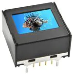
OLED Pushbutton & Display
DISTINCTIVE CHARACTERISTICS
E
Keylocks
Programmable Illuminated PB
Pushbuttons
Rockers
•
•
•
•
•
•
•
•
•
•
•
•
•
Organic LED technology
Life 30,000 hours @ 100cd/m2 (based on 40% pixels on) or
60,000 hours @ 50cd/m2 (based on 40% pixels on)
Power consumption only 3.8mA (30% less than previous product)
Range of 65,536 colors in 16 bit mode, 256 colors in 8 bit mode
Full viewing angle of 180°
Exceptional contrast: 50 times greater than LCD products
Four times more enhanced resolution
High resolution provides sharp, clear images of very small characters
Operated by commands and data supplied via serial communications (SPI)
Distinct, long travel of 4.5mm (same as KP01 series pushbuttons)
Dust tight construction
Stylish, translucent black housing design
Viewing area: 15.5mm x 11.6mm (horizontal x vertical)
Rotaries
High reliability and long life of three million actuations
minimum
High resolution of 64RGB x 48 pixels
Slides
Epoxy sealed straight PC terminals
Tactiles
Snap-in standoff for easy, secure mounting and alignment
Viewing area: 12.9mm x 9.9mm (horizontal x vertical)
Tilt
High resolution of 52RGB x 36 pixels
Touch
Bracket has crimped legs to ensure secure PC mounting
and prevent dislodging during wave soldering
Supplement
Accessories
Indicators
Actual Sizes
Switch
E8
Display
www.nkkswitches.com
10/03/19
�OLED Display
Toggles
ATTENTION
DISPLAY PART NUMBER & DESCRIPTION
Display Description
OLED
Pixel Format
ISC01P
Straight PC Terminals
Color OLED
Display Module
65,536 Colors
52RGB x 36 Pixels
Horizontal x Vertical
OLED SPECIFICATIONS
Characteristics of Display
Display Device
Color OLED display module
Display Mode
Passive matrix
Viewing Area
12.9mm x 9.9mm (horizontal x vertical)
Pixel Format
52RGB x 36 pixels (horizontal x vertical)
Pixel Size
0.21mm x 0.22mm (horizontal x vertical)
Interface
Serial (SPI) interface
Number of Colors
65,536 Colors (16bit: R 5bit/G 6bit/B 5bit)
or 256 Colors (8bit: R 2bit/G 3bit/B 3bit)
Operating Temperature Range
–20°C ~ +70°C (–4°F ~ +158°F)
Storage Temperature Range
–30°C ~ +80°C (–22°F ~ +176°F)
Operating Life (Display)
30,000 hours @ 100cd/m2 (based on 40% pixels ON)
60,000 hours @ 50cd/m2 (based on 40% pixels ON)
Absolute Maximum Ratings
Recommended Operating Conditions
Rotaries
Keylocks
Symbols Minimum
Typical
Maximum
Supply Voltage for
Logic/Interface
VDD
–0.3V to +4.0V
Supply Voltage for
Logic/Interface
VDD
2.4V
2.8V
3.5V
Supply Voltage for Drive
VCC
0.0V to +19.0V
Supply Voltage for Drive
VCC
15.0V
16.0V
17.0V
Input Voltage
VI
–0.3V to VD D +0.3V
Input High Level Voltage
VI H
0.8 x VD D
––
––
Input Low Level Voltage
VI L
––
––
0.2 x VD D
Current Consumption
Optical Characteristics (Temperature at 25°C, Initial Value: 87 x 0F)
All-Pixels-On Mode
*Logic/IF System Power Current
Sleep Mode
**Drive System Power Current
Sleep Mode
**Logic/IF System Power Current
I CC1
I DD1
I CC2
I DD2
––
2.4mA
Max
2.9mA
–– 0.15mA 0.18mA
––
––
––
––
10μA
10μA
*All pixels shall be turned on with the maximum level gray scale
**All pixels shall be turned off (while chip is operating)
Items
Luminosity
Min
Typical
Max
Unit
Remarks
75
100
125
cd/m2
White
(All pixels on)
White Color
Coordinate
(x)
0.25
0.29
0.33
––
(y)
0.31
0.36
0.41
––
Red Color
Coordinate
(x)
0.63
0.67
0.71
––
(y)
0.29
0.33
0.37
––
Green Color
Coordinate
(x)
0.19
0.23
0.27
––
(y)
0.60
0.64
0.68
––
Blue Color
Coordinate
(x)
0.10
0.14
0.18
––
(y)
0.14
0.20
0.26
––
100
––
––
––
Contrast Ratio
www.nkkswitches.com
Indicators
All-Pixels-On Mode
*Drive System Power Current
Symbols Min Typical
Accessories
Items
Supplement
(Temperature at 25°C, VDD = 2.8V, VCC = 16.0V)
Slides
Items
Tactiles
Ratings
Tilt
Symbols
Touch
Items
E
Programmable Illuminated PB
Pushbuttons
Part Number
Rockers
ELECTROSTATIC
SENSITIVE DEVICES
E11
�Toggles
OLED Display
DISPLAY BLOCK DIAGRAM & PIN CONFIGURATIONS
COM1....COM36
Segment Driver
Common Driver
VDD
1
VCC
7
RES
3
SEG/COM
Driving Block
Gray Scale
Decoder
E
ISC01P
SCK
5
SS
2
SDI
6
D/C
4
Oscillator
Graphic Display
Data
RAM
96 x 64 x 16 Bit
Display Timing
Generator
Command Decoder
MCU Interface
GND 8
Rotaries
Pin No.
Slides
Tactiles
SR1,SG1,SB1......SR52,
SG52,SB52
OLED Driver
with Controller
Keylocks
Programmable Illuminated PB
Pushbuttons
Rockers
Color OLED Panel
52RGB x 36
Symbol
Name
Function
1
VDD
Power
Power source for logic circuit
2
SS
Slave Select
Slave select for SPI. This line is active low.
3
RES
Reset
4
D/C
Data/Command
Reset signal input. When pin is low, initialization of chip is
executed.
Data/Command Control. When pin is pulled low, data will
be interpreted as Command; when pulled high, data will be
interpreted as Data.
5
SCK
Serial Clock
Clock line for SPI that synchronizes command and data
6
SDI
Serial Data In
Data input line for SPI
7
VCC
Power
Power source for drive circuit
8
GND
Ground
Connect to Ground
TYPICAL DISPLAY DIMENSIONS
Terminal numbers are not on the switch.
(12.9)
.508
(10.0)
.394
(0.4) Typ
.016
See Standoff
Detail
(0.65) Typ
.026
Tilt
See
Pixel Detail
(17.2)
.677
(9.9)
.390
(7.89)
.311
(16.8)
.661
(14.7)
.579
(5.25)
.207
Touch
(0.75)
.030
(0.7)
.028
(9.9)
.390
Indicators
(10.89)
.429
(17.8)
.701
Accessories
Pixel Detail
Supplement
(0.22) Typ
.0087
(0.03) Typ
.0012
E12
Pixel Detail A
(0.21) Typ
.0083
(0.03) Typ
.0012
See Pixel
Detail A
(0.22)
.0087
(0.19)
.0075
(0.04) Typ
.0016
(0.07) Typ
.0028
R
(0.2) (2.0)
.008 .079
(1.0) Typ
.039
(3.0)
.118
Standoff Detail
(0.2)
.008
R G B R
(0.21)
.0083
www.nkkswitches.com
(0.7)
.028
(0.8) Dia
.031
(1.5) Dia
.059
(0.4) Typ
.016
(7.0)
.276
(15.0)
.591
(2.0)
.079
(15.0)
.591
(10.0)
.394
Footprint
(14.7)
.579
(16.8)
.661
8
1
4x (0.9) Dia
.035
(1.0) Typ
.039
(5.25)
.207
2
7
(7.0)
.276
(2.0)
.079
3x (0.9) Dia
.035
Landless
8x (.075) Dia
.029
�Toggles
OLED Pushbutton & Display
TIMING SPECIFICATIONS FOR SWITCH & DISPLAY
Maximum
Clock Cycle Time
t c yc le
150ns
––
––
D/C Setup Time
t AS
40ns
––
––
D/C Hold Time
t AH
40ns
––
––
SS Setup Time
t CSS
75ns
––
––
SS Hold Time
t CSH
60ns
––
––
Write Data Setup Time
t DSW
40ns
––
––
Write Data Hold Time
t DHW
40ns
––
––
SS
t AS
tA H
t CSS
t CS H
tR
t CLKH
Pushbuttons
D/C
t cy cl e
SCK
t CLKL
tF
t DSW
t DH W
D7
t CLKL
75ns
––
––
SCK High Time
t CLKH
75ns
––
––
SCK Rise Time
tR
––
––
15ns
SCK Fall Time
tF
––
––
15ns
D6
D5
D4
D3
D2
D1
D0
E
Keylocks
SDI
SCK Low Time
Rotaries
STATE TRANSITION
7 : Initialization
4 : Display OFF
8 : Changing the Display
VC C
VD D
Changing the
Display
0
Power OFF
OFF
––
OFF
OFF
Disable
1
Display OFF
OFF
ON
ON
ON
Enable
2
Display ON
ON
OFF
ON
ON
Enable
Display Sleep
Power ON/OFF Sequence
Initialization Setting
State 0
State 1
State 2
State Transition
Transition
1
Power ON
2
Power OFF
Refer to
3
Display ON
"Power ON/OFF Sequence"
4
Display OFF
7
Initialization
Initialize Setting of Command/Data
Image Rewriting
Send Display Data
Display Settings
Dimmer, Scroll, etc.
Power OFF
State 0
Minimum 0µs
Minimum 0µs
VDD
8
Power ON
0V
Index
Reset low pulse width Trw
(minimum 3µs)
RES
“L” or “Hi-z”
“L” or “Hi-z”
Minimum 3µs
Indicators
State
8 : Changing the Display
Minimum 0µs
VCC
D/C
SS
“L” or “Hi-z”
SCK
SDI
VDD level (due to ESD protection
circuit between VDD and VCC)
“H” or “L”
“L” or “Hi-z”
Supplement
State
Number
State 2
Display ON
Slides
3 : Display ON
Tactiles
2 : Power OFF
State 1
Display OFF
(Sleep Mode)
Touch
1 : Power ON, 7 : Initialization
State 0
Power OFF
(VCC, VDD O FF)
Programmable Illuminated PB
Typical
Tilt
Symbols Minimum
Note: Refer to Application Notes on web site.
www.nkkswitches.com
Accessories
Items
Rockers
AC Characteristics (Temperature at 25°C), VDD = 2.4V ~ 3.5V)
E13
�Toggles
OLED Pushbutton & Display
PRECAUTIONS FOR HANDLING & STORAGE OF OLED PUSHBUTTONS & DISPLAY
Rockers
ELECTROSTATIC
SENSITIVE DEVICES
Pushbuttons
1. The IS Series OLED devices are electrostatic sensitive. To avoid damage to IC,
do not touch terminals unless properly isolated from static electricity.
2. Signal input under conditions not recommended may cause damage to the OLED unit or deterioration of the
display. Follow directions regarding supply sequences of power and signal voltages.
3. If the OLED panel is broken, avoid touching the contents. Wash off any contact to the skin or clothing.
4. Limit operating force to switch keytop to 100.0N maximum, as excessive pressure may damage the OLED.
5. For OLED display, it is necessary for bracket legs to be Grounded.
6. Recommended soldering time and temperature limits for OLED switch or display:
E
Avoid temperatures exceeding 80°C at the OLED.
Wave Soldering: see Profile A in Supplement section.
Manual Soldering: see Profile A in Supplement section.
7. The IS series OLED devices are not process sealed.
Keylocks
Programmable Illuminated PB
ATTENTION
Handling
Rotaries
8. Pixels acquire diminished brightness over time and use, and those most frequently habituated have greater
reduction of brightness than those less used. To minimize this difference, operate OLED unit so that all pixels
are used as consistently as possible.
Slides
9. For switch, clean cap surface with dry cloth. If further cleaning is needed, wipe with dampened cloth using
neutral cleanser and dry with clean cloth. Do not use organic solvent. For display, avoid contact with any
flux or detergent. If any liquids spill on display surface, immediately wipe with soft absorbent cloth.
10. Proper serial resistors and buffers for signals should be used to prevent noise problems.
Tactiles
Storage
1. Store in original container and away from direct sunlight.
2. Keep away from static electricity.
Supplement
Accessories
Indicators
Touch
Tilt
3. Avoid extreme temperatures, high humidity, gaseous substances, and all forms of chemical contamination.
E14
www.nkkswitches.com
�Toggles
Optional Accessories
OPTIONAL ACCESSORIES
AT9704-085K Socket for LCD 64 x 32 Pushbutton
Rockers
Materials:
IS15EBFP4RGB
• The socket permits the switch to be plugged in after automated processing.
Pushbuttons
Programmable Illuminated PB
Keylocks
Long Travel LCD 64 x 32
Base - Glass Fiber Reinforced PBT
Terminals - Brass/Beryllium Copper
• Use of the socket enables easy field replacement of the device.
2
9
(20.3)
.799
(6.0)
.236
(7.62)
.300
8
(6.0)
.236
3
(0.5) Dia Typ
.020
E
(22.9)
.902
(1.0) Typ
.039
(4.6)
.181
(7.4)
.291
(8.0)
.315
(7.05)
.278
AT9704-085L Socket for OLED Pushbutton
1
4
(1.0) Typ
.039
9x (0.75) Dia
.030
(7.05)
.278
(2.0)
.079
(2.0)
.079
(7.62)
.300
(8.0)
.315
Compatible Part Numbers for AT9704-085L
Materials:
OLED Pushbutton
Frameless OLED
ISC15ANP4
ISF15ACP4
Base - Glass Fiber Reinforced PBT
Terminals - Brass/Beryllium Copper
• The socket permits the OLED switch to be plugged in after automated processing.
• Use of the socket enables easy field replacement of the device.
Slides
Rotaries
Compatible Part Number for AT9704-085K
(7.0)
.276
Tactiles
(7.62)
.300
(0.5) Dia Typ
.020
(4.2)
.165
(7.0)
.276
(8.0)
.315
(7.05)
.278
(2.0)
.079
4
3
1
(7.62)
.300
10x (0.75) Dia
.030
(1.0) Typ
.039
(2.0)
.079
(7.05)
.278
(8.0)
.315
Tilt
(22.9)
.902
(1.0) Typ
.039
(7.0)
.276
2
10
9
(20.3)
.799
Compatible Part Number for AT9704-085M
AT9704-085M Socket for OLED Display
OLED Display
Base - Glass Fiber Reinforced PBT
Terminals - Brass/Beryllium Copper
ISC01P
• The socket permits the OLED display to be plugged in after automated processing.
• Use of the socket enables easy field replacement of the device.
(16.8)
.661
Accessories
Indicators
Touch
Materials:
(16.8)
.661
7
(10.0)
.394
(17.6)
.693
(7.0)
.276
(1.0) Typ
.039
Supplement
(0.5) DiaTyp
.020
(19.9)
.783
E50
(5.25)
.207
(7.25)
.285
(4.4)
.173
(7.2)
.283
www.nkkswitches.com
(7.0)
.276
(1.0) Typ
.039
(2.0)
.079
1
8
2
(10.0)
.394
12x (0.75) Dia
.030
(5.25)
.207
�
很抱歉,暂时无法提供与“ISC01P”相匹配的价格&库存,您可以联系我们找货
免费人工找货