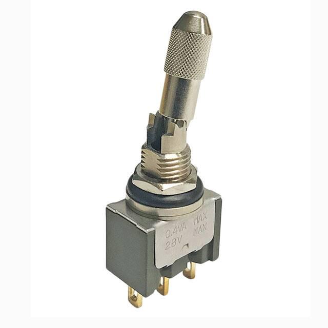
Series M
IP67 Rated Knurled Locking Lever
General Specifications
Electrical Capacity (Resistive Load)
Logic Level (gold): 0.4VA maximum @ 28V AC/DC maximum (Applicable Range 0.1mA ~ 0.1A @ 20mV ~ 28V)
Other Ratings
Contact Resistance: 20 milliohms maximum
Insulation Resistance: 1,000 megohms minimum @ 500V DC
Dielectric Strength: 1,000V AC minimum between contacts for 1 minute minimum;
1,500V AC minimum between contacts and case for 1 minute minimum
Mechanical Life: 50,000 operations minimum
Electrical Life: 50,000 operations minimum
Angle of Throw: 25° ± 4°
Materials & Finishes
Toggle: Brass with chrome plating
Bushing: Brass with nickel plating
Frame: Stainless steel
Case: Diallyl phthalate resin (UL94V–0)
Movable Contactor: Phosphor bronze with gold plating
Movable Contacts: Copper with gold plating
Stationary Contacts: Copper or brass with gold plating
Terminals: Copper or brass with gold plating
Environmental Data
Operating Temperature Range: –30°C through +85°C (–22°F through +185°F)
Humidity: 90 ~ 95% humidity for 96 hours @ 40°C (104°F)
Vibration: 10 ~ 55Hz with peak-to-peak amplitude of 1.5mm traversing the frequency range & returning
in 1 minute; 3 right angled directions for 2 hours
Shock: 50G (490m/s2) acceleration (tested in 6 right angled directions, with 5 shocks in each direction)
Sealing: Splashproof bushing, which has o-rings inside and outside the bushing, meets IP67 of IEC60529
Standards
Installation
Mounting Torque: 0.7Nm (6 lb•in)
Processing
Soldering: Manual Soldering: 390° maximum for 4 seconds maximum; 2 cycles
Note: Lever must be in OFF (center) position while soldering.
Cleaning: These devices are not process sealed. Hand clean locally using alcohol based solution.
Standards & Certifications
Flammability Standards: UL94V–0 for case
UL: File No. E44145 - Recognized only when ordered with marking on switch.
Add “/U” or “/CUL” before dash in part number to order UL recognized switch.
All models recognized at 0.4VA maximum @ 28V DC maximum.
www.nkkswitches.com
1
06/11/19
�Series M
IP67 Rated Knurled Locking Lever
Distinctive Characteristics
Knurled toggle accentuated with textured pattern, facilitating firm nonslip grip.
Inner o-ring and external rubber washer seal the switch to achieve IP67 of
IEC60529 Standards (dust tight and water protected for temporary immersion).
Locking lever prevents accidental actuation.
Antirotation design, standard on noncylindrical levers, mates toggle and bushing;
bottom of toggle has two flatted sides which fit into a complementary opening
inside bushing.
Antijamming design protects contacts from damage due to excessive downward
force on actuator.
High torque bushing construction prevents rotation or separation from frame
during installation.
Molded diallyl phthalate case meets flammability standards for UL94V-0.
Increased insulation resistance and dielectric strength due to prominent
external insulating barriers.
Actual Size
Interlocked actuator block, lever, and interior guide prevent switch failure
due to biased lever movement.
Clinching of frame to case well above base and terminals provides 1,500V
dielectric strength.
Epoxy sealed solder lug terminals prevent entry of solder flux and other
contaminants.
The knurled cap is compatible with other M Series locking levers. Contact NKK
for additional details.
SWITCH PART NUMBER & DESCRIPTION
Part Number
M2013LL3G01-K
Switch Description
Toggle & Bushing
Logic Level (Gold): 0.4VA max @ 28V AC/DC max
(Applicable Range 0.1mA ~ 0.1A @ 20mV ~ 28V)
.681” (17.3mm) Locking Lever
Single Pole Double Throw
ON OFF ON
Solder Lug Terminals
2
www.nkkswitches.com
1/4-40 .291” (7.4mm) Threaded Bushing with D Flat
3 Position Locking Mechanism
AT513H Hex Nut & AT516 O-ring
�Series M
IP67 Rated Knurled Locking Lever
POLE & CIRCUIT
Toggle Position
Pole
Model
Down
Center
Up
Down
Flat
SP
Throw & Schematics
Connected Terminals
Center
Note: Terminal numbers are not
actually on the switch.
Up
Flat
M2013
2 (COM)
SPDT
ON
OFF
ON
2-3
OPEN
3
2-1
1
STANDARD HARDWARE
1/4-40 Thd
AT513H Hex Nut
Brass with
Nickel Plating
AT516 O-ring
Nitrile Butadiene
Rubber
(8.0)
.315
(9.0)
.354
(6.07) Dia
(9.63) Dia
.239
.379
(1.5)
.059
(1.78)
.070
PANEL CUTOUT
For 1/4-40 .291” (7.4mm)
Threaded Splashproof Bushing with D Flat
Maximum Panel Thickness
with Standard Hardware:
.047” (1.2mm)
LOCKING MECHANISM
25°± 4°
Locking Mechanism
ON-OFF-ON
(18.8)
.740
(6.5) Dia
.256
(5.8)
.228
TERMINALS
Solder Lug
(5.1) Dia
.201
Epoxy Seal
(17.3)
.681
(4.0)
.157
(2.0)
.079
(2.0)
(1.1) .079
.043
Thk = (0.8)
.031
1/4-40 Thd
(7.4)
.291
(1.5)
.059
3 Positions Lock
TYPICAL SWITCH DIMENSIONS
Solder Lug
Single Pole
Part No.
This Side
(1.1) x (2.0) Typ
.043 x .079
Flatted
(4.7) Typ
.185
25°± 4°
1/4-40 Thd
(7.9)
.311
(5.1) Dia
.201
(17.3)
.681
(18.8)
.740
(5.9)
.232
(15.4)
.606
(4.5)
.177
(0.8) Typ
.031
(0.5) Typ
.020
3
(13.0)
.512
2
1
(2.0)
.079
M2013LL3G01-K
www.nkkswitches.com
3
�Series M
IP67 Rated Knurled Locking Lever
APPLICATION CONSIDERATIONS
The Knurled Locking Lever is designed as a panel seal switch, and not to be used under water.
Material Properties
The inner o-ring and external rubber washer are made
of nitrile butadiene rubber, which excels in durability
and oil and chemical resistance. Its performance is
less durable with lower weather and ozone resistant
characteristics.
Evaluate the products in regard to your application
and intended environment with these properties in mind.
Repeat opening and closing same as previous test.
The resulting insulation resistance and voltage capacity
are both within the rated values, and water has not
entered inside the switch or installation panel.
Panel Installation
Waterproof Test Conditions
Waterproofing is
measured by subWater Surface
mersing the switch
five centimeters from
the water surface
5cm and 1m
(see illustration),
and opening and
closing 50 times
at a frequency of
50 – 60 times per
minute. The switch
Container
is then submersed
one meter from the
surface and left in
this position for 30 minutes.
Opening
For panel
installation, the
hex nut is
installed above
the panel. The
external o-ring
mounts below
the panel.
Hex Nut
External
O-ring
Applications
• Construction Equipment
• Transportation
• Industrial Control Equipment
4
www.nkkswitches.com
• Medical Equipment
• Machine Tooling
• Marine Equipment
Internal O-ring
Panel
�
很抱歉,暂时无法提供与“M2013LL3G01-K”相匹配的价格&库存,您可以联系我们找货
免费人工找货