Toggles
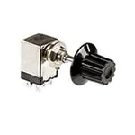
Series MR
Rockers
General Specifications
Electrical Capacity (Resistive Load)
For MRA: 250mA @ 125V AC
Pushbuttons
For MRF or MRK:
Programmable Illuminated PB
Other Ratings
Slides
Rotaries
Keylocks
Contact Resistance:
Insulation Resistance:
Dielectric Strength:
Mechanical Life:
Electrical Life:
Range of Operating Torque:
Contact Timing:
Indexing:
Materials & Finishes
G
Shaft:
Stopper Plate:
Bushing/Housing:
Movable Contacts:
End Contacts & Terminals:
Common Contacts & Terminals:
Base:
Tilt
Tactiles
Environmental Data
Operating Temperature Range:
Humidity:
Vibration:
Shock:
Sealing:
Touch
Installation
Mounting Torque:
Cap Installation Force:
Accessories
Indicators
Processing
Supplement
Half-Inch Diameter Process Sealed Rotaries
Soldering Time & Temperature:
Cleaning:
Standards & Certifications
G16
0.4VA maximum @ 28V AC/DC maximum
(Applicable Range 0.1mA ~ 0.1A @ 20mV ~ 28V)
Note: Find additional explanation of operating range in Supplement section.
10 milliohms maximum for MRA; 50 milliohms maximum for MRF & MRK
100 megohms minimum @ 500V DC
1,000V AC minimum for 1 minute minimum for MRA
500V AC minimum for 1 minute minimum for MRF & MRK
30,000 operations minimum
10,000 operations minimum
0.02 ~ 0.07Nm for MRA; 0.005 ~ 0.02Nm for MRF & MRK
Nonshorting (break-before-make)
MRA – self-cleaning, sliding contact; MRF & MRK – self-cleaning, rotary contactor disk
30°
Brass with nickel plating
Steel with zinc plating for MRA & MRK; polyamide cover with stopper for MRF
Zinc alloy with zinc plating
Copper with silver plating for MRA; phosphor bronze with gold plating for MRF & MRK
Brass with silver plating for MRA; phosphor bronze with gold plating for MRF & MRK
Brass with silver plating for MRA; phosphor bronze with gold plating for MRF & MRK
Diallyl phthalate for MRA; fiberglass reinforced polyamide for MRF & MRK
–10°C through +70°C (+14°F through +158°F)
90 ~ 95% humidity for 96 hours @ 40°C (104°F)
10 ~ 55Hz with peak-to-peak amplitude of 1.5mm traversing the frequency range & returning
in 1 minute; 3 right angled directions for 2 hours
50G (490m/s2) acceleration (tested in 3 right angled directions, with 3 shocks in each direction)
MRK model meets IP67 of IEC60529 standards
.686Nm (6.08 l b • in)
19.6 ~ 29.4N (4.41 ~ 6.61 lbf) for MRA & MRK
Wave Soldering for MRA: See Profile A in Supplement section.
Wave Soldering for MRF & MRK: See Profile B in Supplement section.
Manual Soldering for MRA: See Profile A in Supplement section.
Manual Soldering for MRF & MRK: See Profile B in Supplement section.
Automated cleaning recommended. Stopper plate, as well as washers for MRA & MRK, must be in
place to maintain automated cleaning. See Cleaning specifications in Supplement section.
MRA, MRF, & MRK models have not been tested for UL recognition or CSA certification.
These switches are designed for use in a low-voltage, low-current, logic-level circuit.
When used as intended in a logic-level circuit, the results do not produce hazardous energy.
www.nkkswitches.com
�Toggles
Series MR
Rockers
Distinctive Characteristics
Programmable Illuminated PB
Pushbuttons
Low profile body of MRF model accommodates space limitations
required for PCB mounting. For the MRA and MRK bushing
mount models, the range of behind panel body depths is .323”
to .669” (8.2mm to 17.0mm).
Positive detent mechanism for distinct feel and audible feedback.
Metal bushing and housing construction increases durability.
Keylocks
Adjustable stopper plate allows 2–12 position settings.
High contact reliability achieved by the self-cleaning
contact mechanism.
G
Slides
Break-before-make contact timing with sliding contacts
in MRA and rotary contactor disk in MRF and MRK
models.
Rotaries
Half-Inch Diameter Process Sealed Rotaries
Tactiles
Interior housing seal and molded-in PC terminals, plus shaft
rubber o-ring on MRA and MRK and polyamide cover on MRF
model, allow cleaning after automated soldering.
Tilt
MRK model meets IP67 of IEC60529 specifications (similar to NEMA 4 & 13).
Supplement
Accessories
Indicators
Touch
Actual Size
www.nkkswitches.com
G17
�Series MR
Toggles
Half-Inch Diameter Process Sealed Rotaries
TYPICAL SWITCH ORDERING EXAMPLE
Pushbuttons
Rockers
MR
A
206
Poles & Circuits
Rotaries
Knobs
Colors
A
Shaft Actuated with PC Terminals
112
SP with 2-12 Positions
A
Plain Black
F
Low Profile Screwdriver Actuated
with PC Terminals
206
DP with 2-6 Positions
B
Small Color Tipped
4P with 2-3 Positions
C
Large Color Tipped
K
Low Profile Shaft Actuated with
PC Terminals
403
For Plain Knob
No
Code
Black
For Color Tipped
A
Black
B
White
C
Red
DESCRIPTION FOR TYPICAL ORDERING EXAMPLE
E
Yellow
MRA206-A
F
Green
G
Blue
H
Gray
Keylocks
Programmable Illuminated PB
Actuators & Terminals
A
Shaft Actuated with
Plain Black Knob
G
Slides
DP with 2-6
Adjustable Positions
Tactiles
PC Terminals
Tilt
ACTUATORS & TERMINALS
Shaft Actuated
with PC Terminals
Low Profile
Screwdriver Actuated
with PC Terminals
F
Low Profile
Shaft Actuated
with PC Terminals
K
10
12
11
10
Accessories
1
Supplement
(10.0)
.394
G18
Shaft
6
4 5
1
23
(3.1)
.122
(2.28)
.090
2
(3.5)
.138
(0.5)
.020
Thk = (0.25)
.010
Terminal
1C
89
2
12
11
10 11
9
12
7
Indicators
Touch
A
M
R-
12
2
12 11 10
(3.5)
.138
(0.8)
.031
(3.15) Dia
.124
(1.0)
.039
Slotted for
Screwdriver
www.nkkswitches.com
(0.5)
.020
Thk = (0.25)
.010
Terminal
11
10
9
M R - K 1 1 29
1 C
12 11 10
(3.1)
.122
(2.28)
.090
(10.0)
.394
Shaft
(3.5)
.138
(0.5)
.020
Thk = (0.25)
.010
Terminal
�Series MR
Toggles
Half-Inch Diameter Process Sealed Rotaries
POLES & CIRCUITS
4P
Number of Terminals
MRA112
2–12
2, 3, 4, . . . 12
1 COM, 12 LOAD
MRF112
2–12
2, 3, 4, . . . 12
1 COM, 12 LOAD
MRK112
2–12
2, 3, 4, . . . 12
1 COM, 12 LOAD
MRA206
2–6
2, 3, 4, 5, 6
2 COM, 12 LOAD
MRF206
2–6
2, 3, 4, 5, 6
2 COM, 12 LOAD
MRK206
2–6
2, 3, 4, 5, 6
2 COM, 12 LOAD
MRA403
2–3
2, 3
4 COM, 12 LOAD
MRF403
2–3
2, 3
4 COM, 12 LOAD
MRK403
2–3
2, 3
4 COM, 12 LOAD
Schematics
A
Rockers
Stopper Settings
1
2 3 4 5 6
7 8 9 10 11 12
A
1
B
2 3 4 5 6
A
1
1
2 3 4 5
C
B
2 3 1
2 3
1
Pushbuttons
DP
Number of Positions
6
Programmable Illuminated PB
SP
Model
D
2 3 1
2
3
POSITION SETTING FOR MRA, MRF, & MRK MODELS
MRF Models
Protective Cover
Remove the protective cover from the switch body.
Turn the shaft counterclockwise to the extreme left by using a screwdriver.
Inside the cover is a magnifying lens which would be positioned over the
number which is to be the maximum position used; when the cover is then
snapped into the switch, the projection beside the lens fits into the correct
hole for setting the stop.
23
12
1C
MR
-
12 11 10
Slides
2
Projection
10 11
1
6
4 5
89
MRK & MRA Models
G
Lens
7
Using the actuator knob, turn the shaft
counterclockwise to the extreme left. If
the shaft is not turned counterclockwise
to the extreme left, proper setting cannot be achieved. At this extreme position, the white line on the knob points
to the number 1 position shown on the
side of the switch.
2.
Remove the knob from the shaft and
loosen the nut far enough to allow raising the stopper plate, plus washer(s),
for resetting to the desired position.
Factory Assembled:
3.
Note the position numbers on the side
of the switch; these correspond to the
terminal numbers and stopper holes.
Insert the stopper in the hole numbered
for the maximum desired number of
stop settings. Satisfactory switch functioning cannot be assured if the stopper
plate is not properly positioned.
Metal Washer (MRA)
Tactiles
Standard Mounting Hardware
Packaged Loose with Each Switch:
1.
Hex Face Nut
Tilt
Locking Ring
Lockwasher
Touch
Rubber Ring (MRK)
Hex Nut
Indicators
Stopper Plate
12
2
11
10
9
9
12
M R - K 1 1 29
1 C
Accessories
Rubber Washer
11
10
12 11 10
2
1
4. Tighten the nut (beveled side up) firmly
against the stopper plate.
www.nkkswitches.com
12
11
10
Supplement
1.
2.
3.
Keylocks
Each switch is supplied with the stopper set for the maximum number of positions allowed for that model. Prior to installation,
the desired position setting should be made. Contact factory for continuous rotation.
Rotaries
Pole
G19
�Series MR
Toggles
Half-Inch Diameter Process Sealed Rotaries
TYPICAL SWITCH DIMENSIONS
3
3
2
3
2
1
C
A
3
4
5
6
7
8
4
5
2
Pushbuttons
1
2
1
(6.0)
.236
(10.0)
.394
(16.0) Dia
.630
(17.0)
.669
(5.0)
.197
p
30° Ty
(9.5) Dia
.374
(10.0)
.394
30° Ty
(9.5) Dia
.374
p
30° Ty
(9.5) Dia
.374
p
MRA112
MRF • PC Terminals
3
B
D
C
4
3
5
6
3
3
21
21
4
21
21
5
1 10
6
30°
B
3
21
30°
3
3
21
1
A
2 1
A
12 1 2
(8.2)
.323
(14.0) Dia
.551
6
yp
15° T
(0.5) Typ
.020
(3.5)
.138
(4.2)
.165
7
30°
8
°
15
°
15
°
15
9
(12.0) Dia
.472
5
3 4 5
4 Pole
(0.25) Typ
.010
Cover
6 7 8
G
2 Pole
4
Keylocks
(0.8)
.031
1 Pole
A
2 1
yp
15° T
yp
15° T
(12.6) Dia
.496
(12.6) Dia
.496
(12.6) Dia
.496
1 Pole
3
D
2 1
4
65
1 10
21
3
A
2 1
A
2 1
Tactiles
3
C
2 1
p
B
2 1
Typ
3
4
1
Tilt
15°
30°
5
y
15° T
yp
15° T
yp
15° T
(12.6) Dia
.496
(12.6) Dia
.496
(3.5)
.138
6
(10.1)
.398
B
2 1
3
(5.5)
.217
(10.0)
.394
6
4
(0.5) Typ
.020
(3.1)
.122
7
5
(2.28)
.090
Keyway
8
30°
9
(12.0) Dia
.472
4 Pole
°
15
°
15
(0.25) Typ
.010
M6 P0.75
2 Pole
3
MRK • PC Terminals
1 A
Slides
MRF403
32
Programmable Illuminated PB
6
(1.0)
.039
(3.1)
.122
9 10 11
Rotaries
2
D
2
5
1
1
4
1
10 11
2
B
3
B
6 A
(2.28)
.090
Keyway
(3.0) Dia
.118
(3.0) Dia
.118
3
9
12 A
1
Touch
(3.0) Dia
.118
(0.8) Dia Typ
.031
M6 P0.75
3
Rockers
MRA • PC Terminals
1 Pole
2 Pole
4 Pole
(12.6) Dia
.496
MRK devices are designed to be panel mounted. Installation without panel mounting will affect reliability.
MRK112
9
10
11
2
30
° Typ
G20
1
12
(1.0) Dia Typ
.039
B
4
4
A
5
3
2
30
° Typ
1
1
3
3
5
(9.5) Dia
.374
6
2
90°
A
3
(9.5) Dia
.374
6
2
2
3
B
C
1
A
30°
1
D
3
2
(1.0) Dia Typ
.039
(3.0) Typ
.118
1
Typ
2
(9.5) Dia
.374
7
6
5
8
B
9
10
4
3
(1.0) Dia Typ
.039
(0.8) Dia Typ
.031
3
11
12
2 1 A
15
° Ty
p
www.nkkswitches.com
(12.0) Dia
.472
6
1
(0.8) Dia Typ
.031
2
3
5
4
4
3
15
°
6
2 1 A
Typ
Four Pole
MRF403
MRK403
B
p
8
1
(3.0) Typ
.118
Double Pole
MRF206
MRK206
Single Pole
MRF112
MRK112
5
(12.0) Dia
.472
15° Ty
(3.0) Typ
.118
Four Pole
MRA403
30° Typ
6
5
4
Supplement
7
Double Pole
MRA206
30° Typ
Single Pole
MRA112
180°
Accessories
Indicators
FOOTPRINTS
2
1
C
3
(0.8) Dia Typ
.031
1
2
3
D
1
2
3
3
15°
2 1 A
Typ
(12.0) Dia
.472
�Series MR
Toggles
Half-Inch Diameter Process Sealed Rotaries
KNOBS
Polyamide Tip
Colors:
A, B, C, E, F, G, H
(9.5)
.374
(0.5)
.020
(0.5)
.020
A
Color Codes:
B
Black
C
White
Rockers
(15.8)
.622
Pushbuttons
(14.3)
.563
(9.5)
.374
Programmable Illuminated PB
Polyamide Tip
Colors:
A, B, C, E, F, G, H
(9.5)
.374
(18.0) Dia
.709
(11.0) Dia
.433
(0.5)
.020
E
Red
F
Yellow
Green
G
H
Blue
Gray
MRA & MRK
MRK
Nonsealed Panel
Sealed Panel
Without
Keyway
With
Keyway
(6.35) Dia
.250
(6.5)
.256
(5.6)
.220
(6.35) Dia
.250
(2.2) Dia
.087
With Standard Hardware on Nonsealed Panel:
MRA .067” (1.7mm) MRK .087” (2.2mm)
Without Locking Ring on Nonsealed Panel:
MRA .098” (2.5mm) MRK .118” (3.0mm)
(6.2) Dia
.244
(0.6)
.024
With AT513M & AT535 only on Sealed Panel:
MRK .106” (2.7mm)
(5.4)
.213
AT513M
Metric Hexagon Nut
AT545
Locking Ring
AT509
Lockwasher
AT535
Rubber Ring
Material:
Brass, nickel plating
1 for MRA; 1 for MRK
Material:
Steel, chromate over zinc plating
1 for MRA; 1 for MRK
Material:
Steel, chromate over zinc plating
1 for MRA; 1 for MRK
Material:
Nitrile butadiene rubber
1 for MRK
(6.0)
.236
(8.0)
.315
(6.2) Dia
.244
(11.6)
.457
(2.0)
.079
(6.4) Dia (10.2) Dia
.252
.402
Tilt
M6 P0.75
(9.4) Dia
.370
(1.7)
.067
(0.5)
.020
(0.8)
.031
(1.3)
.051
Indicators
(1.5)
.059
Touch
(12.0)
.472
(9.0)
.354
OPTIONAL SUPPORT BRACKET
AT543
Support Bracket for MRK
Material:
Steel with tin plating
(18.0)
.709
(18.0)
.709
(17.5)
.689
(14.9)
.587
(3.8) Typ
.150
(0.5) Typ
.020
(14.0)
.551
(0.8) Typ
.031
G
Slides
STANDARD MOUNTING HARDWARE
(5.5)
.217
Keylocks
PANEL CUTOUTS & MAXIMUM EFFECTIVE PANEL THICKNESS
Rotaries
(13.0)
.512
Base Material:
Polyester
Base Color:
Black
(16.0) Dia
.630
(9.5) Dia
.374
Tactiles
(19.0) Dia
.748
(11.0) Dia
.433
AT4104 Large
Color Tipped
C
Base Material:
Polyester
Base Color:
Black
Material:
Polyacetal
Color:
Black
only
AT4103 Small
Color Tipped
B
(17.2)
.677
(1.2) Dia Typ
.047
www.nkkswitches.com
A support bracket
is needed when
the MRK is mounted
only to a PC board
and does not have
the bushing through
a panel.
G21
Accessories
AT433
Plain Black
Supplement
A
�


 工商网监
湘ICP备2023018690号
工商网监
湘ICP备2023018690号
