UB25NKW01N-F

UB25NKW01N-F

  • 厂商:

    NKK

  • 封装:

  • 描述:

    UB25NKW01N-F - Distinctive Characteristics - Nihon Kaiheiki Industry Co. Ltd.

  • 详情介绍
  • 数据手册
  • 价格&库存
UB25NKW01N-F 数据手册
Distinctive Characteristics Square or rectangular models. Combination of PCB mountability and short body allows use in compact applications. Small behind panel dimension for snap-in mounting in tight spaces. Snap-acting contact mechanism provides sensitive actuation with audible feedback; quick-make, quick-break characteristic limits arcing and prolongs electrical life. Latchdown mechanism, independent of switching mechanism, gives visible and tactile indication of circuit status. Terminals are epoxy sealed to lock out flux, solvents, and other contaminants. Momentary and alternate action circuits available in the same space-saving body size. Illuminated models available and shown in Illuminated Pushbutton section. Matching indicators available and shown at the end of Section M. Actual Size N KK Switches • email: sales@nkkswitches.com • Phone (480) 991-0942 • Fax (480) 998-1435 • www.nkkswitches.com 03-07 General Specifications Electrical Capacity (Resistive Load) Power Level (code W): Logic Level (code G): 5A @ 125/250V AC or 5A @ 30V DC 0.4VA maximum @ 28V AC/DC maximum (Applicable Range 0.1mA ~ 0.1A @ 20mV ~ 28V) Note: Find additional explanation of operating range in Supplement section. Other Ratings Contact Resistance: Insulation Resistance: Dielectric Strength: Mechanical Life: Electrical Life: Nominal Operating Force: Contact Timing: Travel: 50 milliohms maximum for silver; 100 milliohms maximum for gold 200 megohms minimum @ 500V DC 1,000V AC minimum between contacts for 1 minute minimum; 1,500V AC minimum between contacts & case for 1 minute minimum 1,000,000 operations minimum for momentary; 200,000 operations minimum for alternate action 10,000 operations minimum for silver; 100,000 operations minimum for silver with resistive load of 3A @ 125V AC 200,000 operations minimum for gold Single Pole: 1.57N for Square & 1.9N for Rectangular Double Pole: 2.55N for Square & 3.1N for Rectangular Break before make Pretravel .067” (1.7mm); Overtravel .024” (0.6mm); Total Travel .091” (2.3mm) Materials & Finishes Housing/Bezel: Snap-in Frame: Movable Contactor: Movable Contacts: Stationary Contacts: Terminals: Base: Glass fiber reinforced polyamide (UL94V-0) Stainless steel Phosphor bronze Silver alloy or copper with gold plating Silver alloy or copper with gold plating Phosphor bronze with silver or gold plating Glass fiber reinforced liquid crystal polymer (UL94V-0) Environmental Data Operating Temp Range: Humidity: Vibration: Shock: –20°C through +70°C (–4°F through +158°F) 90 ~ 95% humidity for 96 hours @ 40°C (104°F) 10 ~ 55Hz with peak-to-peak amplitude of 1.5mm traversing the frequency range & returning in 1 minute; 3 right angled directions for 2 hours 50G (490m/s2) acceleration (tested in 6 right angled directions, with 5 shocks in each direction) Installation Cap Installation Force: Soldering Time & Temp: Cleaning: 7.55N (1.70 lbf) maximum downward force on cap Wave Soldering (PC version): See Profile A in Supplement section. Manual Soldering: See Profile A in Supplement section. These devices are not process sealed. Hand clean locally using alcohol based solution. Standards & Certifications Flammability Standards: UL & C-UL Recognized: R CSA Certified: UL94V-0 housing/bezel of GFR polyamide & base of GFR liquid crystal polymer All single & double pole models recognized at 5A @ 125/250V AC or 0.014A @ 28V DC; UL File No. WOYR2.E44145; add “/U” to end of part number to order UL mark on switch; C-UL File No. WOYR8.E44145; add “/C-UL” to end of part number to order C-UL mark on switch. All single & double pole models certified at 5A @ 125/250V AC or 5A @ 30V DC or 0.4VA maximum @ 28V AC/DC maximum; CSA File No. 023535-0-000; add “/C” to end of part number to order CSA mark on switch. N KK Switches • email: sales@nkkswitches.com • Phone (480) 991-0942 • Fax (480) 998-1435 • www.nkkswitches.com 03-07 TYPICAL SWITCH ORDERING EXAMPLE UB 1 5 SK G 03 N C POLES 1 2 SPDT DPDT MOUNTING TYPES PCB Mounting SK RK KK Square Rectangular Square Rectangular Rectangular with Side Barriers TERMINALS Solder Lug (for 01 Snap-in Mounting) 03 Straight PC B C E F CAP COLORS A Black White Red Yellow Green * Snap-in Mounting NK NBK CIRCUITS 5 6 ON ON (ON) ON ( ) = Momentary Alternate Action with Latchdown CONTACTS & RATINGS W G Silver Rated 5A @ 125/250V AC Gold Rated 0.4VA max @ 28V AC/DC max * Standard with Solder Lug terminals G Blue Note: Insert Cap with clear lens and colored filter available; see Illuminated Pushbuttons section DESCRIPTION FOR TYPICAL ORDERING EXAMPLE UB15SKG03N-C Red Cap Gold Contacts with 0.4VA Rating Square with PCB Mounting SPDT ON-(ON) Circuit Straight PC Terminals IMPORTANT: Switches are supplied without UL, C-UL, & CSA markings unless specified. Specific models & ratings noted on General Specifications page. N KK Switches • email: sales@nkkswitches.com • Phone (480) 991-0942 • Fax (480) 998-1435 • www.nkkswitches.com 03-07 POLES & CIRCUITS Plunger Position ( ) = Momentary Normal Pole SP DP Model UB15 *UB16 UB25 *UB26 ON ON ON ON (ON) ON (ON) ON 1-3 1-3 4-6 1-2 1-2 4-5 Down Connected Terminals Normal Down Throw & Schematics Note: Switch is marked with NC, NO, COM, L+ & L– even though nonilluminated models have no lamp terminals. SPDT 3 1 COM NO 6 1 NC COM 2 NO 4 NC COM 5 NO DPDT 3 NC 2 * When in latchdown position for the alternate circuit, cap position is .039” (1.0mm) above the housing. MOUNTING TYPES & SHAPES PCB Mounting SK Square (5.08) .200 3 (5.08) Typ .200 6 RK 3 2 1 Rectangular (7.62) .300 3 2 1 6 (7.62) Typ .300 3 2 1 (5.08) Typ .200 5 4 (5.08) Typ .200 (5.08) Typ .200 5 4 2 1 (5.08) Typ .200 C L (1.2) Dia Typ .047 C L (1.2) Dia Typ .047 C L (1.2) Dia Typ .047 C L (1.2) Dia Typ .047 Single Pole Double Pole Snap-in Mounting (Solder Lug) Single Pole Double Pole KK Square with Built-in Bezel NK Rectangular with Built-in Bezel NBK Rectangular with Built-in Side Barriers (16.2) .638 (16.2) Sq .638 (22.4) .882 Snap-in Mounting with Solder Lug terminals is the standard combination. Panel Thickness: .039 ~ .126” (1.0 ~ 3.2mm) CONTACT MATERIALS & RATINGS W G Silver Contacts Power Level 5A @ 125V AC & 250V AC Gold Contacts Logic Level 0.4VA maximum @ 28V AC/DC maximum Complete explanation of operating range in Supplement section. T ERMINALS 01 Solder Lug (1.6) .063 (0.2) .008 (5.0) .197 03 Straight PC (2.0) .079 (0.8) .032 Thk = (0.5) .020 (0.2) .008 (4.0) .157 (1.0) .039 Thk = (0.5) .020 N KK Switches • email: sales@nkkswitches.com • Phone (480) 991-0942 • Fax (480) 998-1435 • www.nkkswitches.com 03-07 CAPS & COLORS Colors Available: AT4073 Square Opaque AT4116 Rectangular Opaque (3.0) .118 (12.0) Sq .472 (12.0) .472 (17.0) .669 (3.0) .118 A B C Black White Red E F G Yellow Green Blue Material: Polycarbonate Finish: Glossy TYPICAL SWITCH DIMENSIONS Square • PCB Mount Single & Double Pole (0.5) .020 3 N.C. L+ 6 N.C. (12.0) Sq .472 (0.5) Typ .020 (10.0) (4.0) .394 .157 Latchdown Position 2 N.O. COM 5 N.O. COM L- (5.08) Typ .200 1 4 (15.24) Sq .600 (2.5) .098 (1.0) .039 (1.0) Typ .039 (5.08) Typ .200 UB15SKG03N-C Single pole models do not have terminals 4, 5, & 6. Rectangular • PCB Mount Single & Double Pole (0.5) .020 3 N.C. L+ (12.0) .472 (15.24) .600 (17.0) .669 (2.5) .098 (1.0) .039 (0.5) Typ .020 (4.0) .157 Latchdown Position (10.0) .394 6 N.C. 2 N.O. COM. 5 N.O. COM L- (5.08) Typ .200 1 4 (20.32) .800 (7.62) Typ .300 (1.0) Typ .039 UB26RKG03N-E Single pole models do not have terminals 4, 5, & 6. Square • Snap-in Mount • Built-in Bezel Single & Double Pole (1.4) .055 (0.8) x (1.6) Typ .032 x .063 3 N.C. L+ 6 N.C. (12.0) Sq .472 (0.5) Typ .020 (10.0) (5.0) .394 .197 Latchdown Position 2 N.O. COM 5 N.O. COM L- 1 4 (5.08) Typ .200 (15.8) .622 (17.8) Sq .701 (2.5) .098 (1.0) .039 (2.0) Typ .079 (5.08) Typ .200 UB25KKW01N-C Single pole models do not have terminals 4, 5, & 6. Rectangular • Snap-in Mount • Built-in Bezel Single & Double Pole (1.4) .055 (0.8) x (1.6) Typ .032 x .063 3 L+ 6 N.C. (12.0) .472 (17.8) .701 (0.5) Typ .020 (10.0) (5.0) .394 .197 Latchdown Position N.C. 2 N.O. COM. 5 N.O. COM L- 1 4 (5.08) Typ .200 (15.8) .622 (17.0) .669 (24.0) .945 (2.5) .098 (1.0) .039 (7.62) Typ .300 (22.0) .866 (2.0) Typ .079 UB26NKW01N-F Single pole models do not have terminals 4, 5, & 6. 03-07 N KK Switches • email: sales@nkkswitches.com • Phone (480) 991-0942 • Fax (480) 998-1435 • www.nkkswitches.com TYPICAL SWITCH DIMENSIONS Rectangular • Snap-in Mount • Built-in Side Barriers Single & Double Pole (0.8) x (1.6) Typ .032 x .063 3 L+ 6 N.C. (12.0) .472 (17.8) .701 (0.5) Typ .020 (24.0) .945 (3.9) .154 (8.6) .339 (5.0) .197 N.C. 2 N.O. COM. 5 N.O. COM L- (5.08) Typ .200 (15.8) .622 1 4 (17.0) .669 (7.62) Typ .300 (22.0) .866 (2.0) Typ .079 UB25NBKW01N-F Single pole models do not have terminals 4, 5, & 6. OPTIONAL ACCESSORIES AT4001 Square Dust Cover (15.0) Sq .591 Not for use with barrier type models (mounting code NBK) (16.5) .650 (16.5) .650 (24.0) .945 AT4011 Rectangular Dust Cover Cap Height When Assembled (7.3) .287 (2.5) .098 (24.0) Sq .945 (22.7) .894 (30.2) 1.189 Materials: PVC with polyethylene gasket (PVC loses pliability below 0°C (32°F).) Recommended Panel Thickness: .039” ~ .098” (1.0mm ~ 2.5mm) Spring Loaded Protective Guard for Snap-in Mounting of Square PCB Model AT4173 Square Protective Guard/ Snap-in Frame Opens 180° Closes automatically Materials: Cover: Clear Polycarbonate Base: Black Polyamide Coil Spring: Stainless Steel Recommended Panel Thickness: .039” ~ .126” (1.0mm ~ 3.2mm) Recommended Panel-to-PCB Range: .354” ~ .433” (9.0mm ~ 11.0mm) (18.2) Sq .717 (10.5) .413 (20.5) .807 (15.64) .616 (18.4) .724 (20.4) .803 (6.0) .236 (9.0) .354 (15.64) .616 180° AT 4173 (10.5) .413 (20.5) .807 (39.0) Min* 1.535 2 Protective Guard Panel Installation 1 Install switch onto PC board. 2 Snap protective guard into panel. 3 Join the two assemblies. 3 Switch 1 (20.4) .803 (9.0) ~ (11.0) .354 ~ .433 (20.4) .803 (N) (N) = Number of switches * Minimum dimension allows opening of cover to 180° PC Board N KK Switches • email: sales@nkkswitches.com • Phone (480) 991-0942 • Fax (480) 998-1435 • www.nkkswitches.com 03-07 OPTIONAL ACCESSORIES Spring Loaded Protective Guard for Square Snap-in Model AT4171 Square Protective Guard Opens 180° Closes automatically (10.5) .413 (20.5) .807 Cap Height When Assembled (17.9) .705 (7.1) .280 (18.4) .724 (16.2) Sq .638 (39.0) Min* 1.535 (20.4) .803 (7.5) .295 (14.2) .559 (17.9) .705 AT 4171 (10.5) .413 (20.5) .807 180° Materials: Cover: Clear Polycarbonate Base: Black GFR Polyamide Coil Spring: Stainless Steel (20.4) .803 (20.4) .803 (N) Recommended Panel Thickness: .039” ~ .106” (1.0mm ~ 2.7mm) (N) = Number of switches * Minimum dimension allows opening of cover to 180° Spring Loaded Protective Guard for Snap-in Mounting of Rectangular PCB Model AT4174 Rectangular Protective Guard/ Snap-in Frame Opens 180° Closes automatically Materials: Cover: Clear Polycarbonate Base: Black Polyamide Coil Spring: Stainless Steel Recommended Panel Thickness: .039” ~ .126” (1.0mm ~ 3.2mm) Recommended Panel-to-PCB Range: .354” ~ .433” (9.0mm ~ 11.0mm) (18.2) .717 (39.0) Min* 1.535 2 (10.5) .413 (20.5) .807 (15.64) .616 (24.6) .969 (23.4) .921 (26.6) 1.047 (6.0) .236 (9.0) .354 180° (20.54) .809 AT4174 (10.5) .413 (20.5) .807 Protective Guard Panel I nstallation 1 Install switch onto PC board. 2 Snap protective guard into panel. 3 Join the two assemblies. 3 Switch 1 (9.0) ~ (11.0) .354 ~ .433 (26.6) 1.047 (26.6) 1.047 (N) (N) = Number of switches * Minimum dimension allows opening of cover to 180° PC Board N KK Switches • email: sales@nkkswitches.com • Phone (480) 991-0942 • Fax (480) 998-1435 • www.nkkswitches.com 03-07 OPTIONAL ACCESSORIES Spring Loaded Protective Guard for Rectangular Snap-in Model AT4172 Rectangular Protective Guard Opens 180° Closes automatically (10.5) .413 (20.5) .807 Cap Height When Assembled (17.9) .705 (7.1) .280 (24.6) .969 (22.4) .882 (26.6) 1.047 (7.5) .295 (20.4) .803 (24.1) .949 (16.2) .638 180° (39.0) Min* 1.535 AT4172 (10.5) .413 (20.5) .807 Materials: Cover: Clear Polycarbonate Base: Black GFR Polyamide Coil Spring: Stainless Steel (26.6) 1.047 (26.6) 1.047 (N) * Minimum dimension allows opening of cover to 180° Recommended Panel Thickness: .039” ~ .106” (1.0mm ~ 2.7mm) (N) = Number of switches LEGENDS Easily create and submit your own legends using our new on-line Legend Maker. Visit www.nkkswitches.com For other legend support options, customers may either contact the factory and request the UB/UB2 Legend Packet, or utilize the general information and basic specifications presented below. N KK Switches • email: sales@nkkswitches.com • Phone (480) 991-0942 • Fax (480) 998-1435 • www.nkkswitches.com LM Suggested Printable Area for UB Lens Recommended Methods: Laser Etch on clear lens; Screen Print or Pad Print on lens. Epoxy based ink is recommended. (10.48) (12.0) .413 .472 P U (10.48) Sq .413 (12.0) Sq .472 (0.76) Typ .030 (0.76) Typ .030 (15.48) .609 (17.0) .669 (0.76) Typ .030 Shaded areas are printable areas. 03-07
UB25NKW01N-F
### 物料型号 - 型号代码由多个部分组成,例如“UB15SKG03N-C”,其中“UB”可能表示系列,“15”表示尺寸,“SK”表示安装方式为PCB安装且为方形,“G”表示逻辑级别,“03”表示触点数量,“N”表示触点材料为银,“C”表示认证标记。 - 其他型号如“UB26RKG03N-E”和“UB25NBKW01N-F”遵循类似的编码规则。

### 器件简介 - NKK开关具有方形或矩形模型,结合了PCB安装性和短体设计,适用于紧凑应用。 - 小型后面板尺寸适合在狭小空间内快速安装。 - 快动接触机制提供灵敏的操作和声音反馈,快速形成和快速断开的特性限制了电弧并延长了电气寿命。 - 独立的锁定机制提供可见和触觉的电路状态指示。

### 引脚分配 - 单极(SP)和双极(DP)模型有不同的引脚连接方式,例如SP模型“UB15 UB16”在常态下连接1-3,在按下时连接1-2,为SPDT(单刀双掷)。 - DP模型“UB25 UB26”在常态下连接1-34-6,在按下时连接1-24-5,为DPDT(双刀双掷)。

### 参数特性 - 
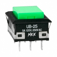
电阻负载功率等级(W代码):5A @ 125/250V AC或5A @ 30V DC。 - 逻辑等级(G代码):最大0.4VA @ 28V AC/DC。 - 接触电阻:银最大50毫欧姆,金最大100毫欧姆。 - 绝缘电阻:最小200兆欧姆 @ 500V DC。 - 耐压:接触间1000V AC至少1分钟;接触与外壳间1500V AC至少1分钟。 - 机械寿命:瞬时动作最小100万次操作;交替动作最小20万次操作。 - 电气寿命:银触点最小10万次操作;金触点最小20万次操作。

### 功能详解 - 开关具有瞬时和交替动作电路,且具有相同节省空间的尺寸。 - 有带照明的型号,并在“照明按钮”部分展示。 - 匹配的指示器在“第M节”末尾展示。

### 应用信息 - 开关适用于需要高电气和机械寿命的应用,如工业控制、医疗设备和消费电子产品。

### 封装信息 - 封装材料包括玻璃纤维增强聚酰胺(UL94V-0)、不锈钢、磷青铜、银合金或铜镀金。 - 操作温度范围为–20°C至+70°C。 - 湿度、振动和冲击测试符合特定标准。
UB25NKW01N-F 价格&库存

很抱歉,暂时无法提供与“UB25NKW01N-F”相匹配的价格&库存,您可以联系我们找货

免费人工找货