Distinctive Characteristics
Square or rectangular models. Combination of PCB mountability and short body allows use in compact applications. Small behind panel dimension for snap-in mounting in tight spaces. Snap-acting contact mechanism provides sensitive actuation with audible feedback; quick-make, quick-break characteristic limits arcing and prolongs electrical life. Latchdown mechanism, independent of switching mechanism, gives visible and tactile indication of circuit status. Terminals are epoxy sealed to lock out flux, solvents, and other contaminants. Momentary and alternate action circuits available in the same space-saving body size. Illuminated models available and shown in Illuminated Pushbutton section. Matching indicators available and shown at the end of Section M.
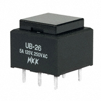
Actual Size
N KK Switches • email: sales@nkkswitches.com • Phone (480) 991-0942 • Fax (480) 998-1435 • www.nkkswitches.com
03-07
�General Specifications
Electrical Capacity (Resistive Load)
Power Level (code W): Logic Level (code G): 5A @ 125/250V AC or 5A @ 30V DC 0.4VA maximum @ 28V AC/DC maximum (Applicable Range 0.1mA ~ 0.1A @ 20mV ~ 28V) Note: Find additional explanation of operating range in Supplement section.
Other Ratings
Contact Resistance: Insulation Resistance: Dielectric Strength: Mechanical Life: Electrical Life:
Nominal Operating Force: Contact Timing: Travel:
50 milliohms maximum for silver; 100 milliohms maximum for gold 200 megohms minimum @ 500V DC 1,000V AC minimum between contacts for 1 minute minimum; 1,500V AC minimum between contacts & case for 1 minute minimum 1,000,000 operations minimum for momentary; 200,000 operations minimum for alternate action 10,000 operations minimum for silver; 100,000 operations minimum for silver with resistive load of 3A @ 125V AC 200,000 operations minimum for gold Single Pole: 1.57N for Square & 1.9N for Rectangular Double Pole: 2.55N for Square & 3.1N for Rectangular Break before make Pretravel .067” (1.7mm); Overtravel .024” (0.6mm); Total Travel .091” (2.3mm)
Materials & Finishes
Housing/Bezel: Snap-in Frame: Movable Contactor: Movable Contacts: Stationary Contacts: Terminals: Base:
Glass fiber reinforced polyamide (UL94V-0) Stainless steel Phosphor bronze Silver alloy or copper with gold plating Silver alloy or copper with gold plating Phosphor bronze with silver or gold plating Glass fiber reinforced liquid crystal polymer (UL94V-0)
Environmental Data
Operating Temp Range: Humidity: Vibration: Shock:
–20°C through +70°C (–4°F through +158°F) 90 ~ 95% humidity for 96 hours @ 40°C (104°F) 10 ~ 55Hz with peak-to-peak amplitude of 1.5mm traversing the frequency range & returning in 1 minute; 3 right angled directions for 2 hours 50G (490m/s2) acceleration (tested in 6 right angled directions, with 5 shocks in each direction)
Installation
Cap Installation Force: Soldering Time & Temp: Cleaning:
7.55N (1.70 lbf) maximum downward force on cap Wave Soldering (PC version): See Profile A in Supplement section. Manual Soldering: See Profile A in Supplement section. These devices are not process sealed. Hand clean locally using alcohol based solution.
Standards & Certifications
Flammability Standards: UL & C-UL Recognized:
R
CSA Certified:
UL94V-0 housing/bezel of GFR polyamide & base of GFR liquid crystal polymer All single & double pole models recognized at 5A @ 125/250V AC or 0.014A @ 28V DC; UL File No. WOYR2.E44145; add “/U” to end of part number to order UL mark on switch; C-UL File No. WOYR8.E44145; add “/C-UL” to end of part number to order C-UL mark on switch. All single & double pole models certified at 5A @ 125/250V AC or 5A @ 30V DC or 0.4VA maximum @ 28V AC/DC maximum; CSA File No. 023535-0-000; add “/C” to end of part number to order CSA mark on switch.
N KK Switches • email: sales@nkkswitches.com • Phone (480) 991-0942 • Fax (480) 998-1435 • www.nkkswitches.com
03-07
�TYPICAL SWITCH ORDERING EXAMPLE
UB
1
5
SK
G
03
N
C
POLES
1 2 SPDT DPDT
MOUNTING TYPES
PCB Mounting SK RK KK Square Rectangular Square Rectangular Rectangular with Side Barriers
TERMINALS
Solder Lug (for 01 Snap-in Mounting) 03 Straight PC B C E F
CAP COLORS
A Black White Red Yellow Green
* Snap-in Mounting NK NBK
CIRCUITS
5 6 ON ON (ON) ON ( ) = Momentary Alternate Action with Latchdown
CONTACTS & RATINGS
W G Silver Rated 5A @ 125/250V AC Gold Rated 0.4VA max @ 28V AC/DC max
* Standard with Solder Lug terminals
G Blue Note: Insert Cap with clear lens and colored filter available; see Illuminated Pushbuttons section
DESCRIPTION FOR TYPICAL ORDERING EXAMPLE
UB15SKG03N-C
Red Cap Gold Contacts with 0.4VA Rating Square with PCB Mounting SPDT ON-(ON) Circuit Straight PC Terminals
IMPORTANT:
Switches are supplied without UL, C-UL, & CSA markings unless specified. Specific models & ratings noted on General Specifications page.
N KK Switches • email: sales@nkkswitches.com • Phone (480) 991-0942 • Fax (480) 998-1435 • www.nkkswitches.com
03-07
�POLES & CIRCUITS
Plunger Position ( ) = Momentary Normal Pole SP DP Model UB15 *UB16 UB25 *UB26 ON ON ON ON (ON) ON (ON) ON 1-3 1-3 4-6 1-2 1-2 4-5 Down Connected Terminals Normal Down Throw & Schematics Note: Switch is marked with NC, NO, COM, L+ & L– even though nonilluminated models have no lamp terminals. SPDT
3 1 COM NO 6 1 NC COM 2 NO 4 NC COM 5 NO
DPDT
3
NC 2
* When in latchdown position for the alternate circuit, cap position is .039” (1.0mm) above the housing.
MOUNTING TYPES & SHAPES
PCB Mounting
SK
Square
(5.08) .200
3
(5.08) Typ .200
6
RK
3 2 1
Rectangular
(7.62) .300
3 2 1
6
(7.62) Typ .300
3
2 1
(5.08) Typ .200
5 4
(5.08) Typ .200
(5.08) Typ .200
5 4
2 1
(5.08) Typ .200
C L
(1.2) Dia Typ .047
C L
(1.2) Dia Typ .047
C L
(1.2) Dia Typ .047
C L
(1.2) Dia Typ .047
Single Pole
Double Pole Snap-in Mounting (Solder Lug)
Single Pole
Double Pole
KK
Square with Built-in Bezel
NK
Rectangular with Built-in Bezel
NBK
Rectangular with Built-in Side Barriers
(16.2) .638
(16.2) Sq .638 (22.4) .882
Snap-in Mounting with Solder Lug terminals is the standard combination. Panel Thickness: .039 ~ .126” (1.0 ~ 3.2mm)
CONTACT MATERIALS & RATINGS W G
Silver Contacts Power Level 5A @ 125V AC & 250V AC
Gold Contacts
Logic Level
0.4VA maximum @ 28V AC/DC maximum
Complete explanation of operating range in Supplement section.
T ERMINALS 01
Solder Lug
(1.6) .063 (0.2) .008 (5.0) .197
03
Straight PC
(2.0) .079 (0.8) .032 Thk = (0.5) .020
(0.2) .008 (4.0) .157 (1.0) .039 Thk = (0.5) .020
N KK Switches • email: sales@nkkswitches.com • Phone (480) 991-0942 • Fax (480) 998-1435 • www.nkkswitches.com
03-07
�CAPS & COLORS
Colors Available: AT4073 Square Opaque AT4116 Rectangular Opaque
(3.0) .118 (12.0) Sq .472 (12.0) .472 (17.0) .669 (3.0) .118
A B C
Black White Red
E F G
Yellow Green Blue
Material: Polycarbonate
Finish: Glossy
TYPICAL SWITCH DIMENSIONS
Square • PCB Mount Single & Double Pole
(0.5) .020
3
N.C. L+
6
N.C.
(12.0) Sq .472 (0.5) Typ .020 (10.0) (4.0) .394 .157 Latchdown Position
2
N.O. COM
5
N.O. COM L-
(5.08) Typ .200
1
4
(15.24) Sq .600
(2.5) .098 (1.0) .039
(1.0) Typ .039 (5.08) Typ .200
UB15SKG03N-C
Single pole models do not have terminals 4, 5, & 6.
Rectangular • PCB Mount
Single & Double Pole
(0.5) .020
3
N.C. L+
(12.0) .472 (15.24) .600 (17.0) .669 (2.5) .098 (1.0) .039 (0.5) Typ .020 (4.0) .157 Latchdown Position (10.0) .394
6
N.C.
2
N.O. COM.
5
N.O. COM L-
(5.08) Typ .200
1
4
(20.32) .800
(7.62) Typ .300
(1.0) Typ .039
UB26RKG03N-E
Single pole models do not have terminals 4, 5, & 6.
Square • Snap-in Mount • Built-in Bezel
Single & Double Pole
(1.4) .055 (0.8) x (1.6) Typ .032 x .063
3
N.C. L+
6
N.C.
(12.0) Sq .472 (0.5) Typ .020 (10.0) (5.0) .394 .197 Latchdown Position
2
N.O. COM
5
N.O. COM L-
1
4
(5.08) Typ .200 (15.8) .622
(17.8) Sq .701
(2.5) .098 (1.0) .039
(2.0) Typ .079 (5.08) Typ .200
UB25KKW01N-C
Single pole models do not have terminals 4, 5, & 6.
Rectangular • Snap-in Mount • Built-in Bezel
Single & Double Pole
(1.4) .055 (0.8) x (1.6) Typ .032 x .063
3
L+
6
N.C.
(12.0) .472 (17.8) .701 (0.5) Typ .020 (10.0) (5.0) .394 .197 Latchdown Position
N.C.
2
N.O. COM.
5
N.O. COM L-
1
4
(5.08) Typ .200 (15.8) .622
(17.0) .669 (24.0) .945
(2.5) .098 (1.0) .039
(7.62) Typ .300 (22.0) .866
(2.0) Typ .079
UB26NKW01N-F
Single pole models do not have terminals 4, 5, & 6. 03-07
N KK Switches • email: sales@nkkswitches.com • Phone (480) 991-0942 • Fax (480) 998-1435 • www.nkkswitches.com
�TYPICAL SWITCH DIMENSIONS
Rectangular • Snap-in Mount • Built-in Side Barriers Single & Double Pole
(0.8) x (1.6) Typ .032 x .063
3
L+
6
N.C.
(12.0) .472 (17.8) .701 (0.5) Typ .020 (24.0) .945 (3.9) .154 (8.6) .339 (5.0) .197
N.C.
2
N.O. COM.
5
N.O. COM L-
(5.08) Typ .200 (15.8) .622
1
4
(17.0) .669
(7.62) Typ .300 (22.0) .866
(2.0) Typ .079
UB25NBKW01N-F
Single pole models do not have terminals 4, 5, & 6.
OPTIONAL ACCESSORIES
AT4001 Square Dust Cover
(15.0) Sq .591
Not for use with barrier type models (mounting code NBK)
(16.5) .650
(16.5) .650 (24.0) .945
AT4011 Rectangular Dust Cover
Cap Height When Assembled (7.3) .287
(2.5) .098 (24.0) Sq .945
(22.7) .894
(30.2) 1.189
Materials: PVC with polyethylene gasket (PVC loses pliability below 0°C (32°F).) Recommended Panel Thickness: .039” ~ .098” (1.0mm ~ 2.5mm) Spring Loaded Protective Guard for Snap-in Mounting of Square PCB Model AT4173 Square Protective Guard/ Snap-in Frame Opens 180° Closes automatically Materials: Cover: Clear Polycarbonate Base: Black Polyamide Coil Spring: Stainless Steel Recommended Panel Thickness: .039” ~ .126” (1.0mm ~ 3.2mm) Recommended Panel-to-PCB Range: .354” ~ .433” (9.0mm ~ 11.0mm)
(18.2) Sq .717
(10.5) .413 (20.5) .807 (15.64) .616
(18.4) .724
(20.4) .803
(6.0) .236
(9.0) .354
(15.64) .616
180°
AT 4173 (10.5) .413 (20.5) .807
(39.0) Min* 1.535
2
Protective Guard Panel
Installation 1 Install switch onto PC board. 2 Snap protective guard into panel. 3 Join the two assemblies.
3
Switch
1
(20.4) .803 (9.0) ~ (11.0) .354 ~ .433 (20.4) .803 (N) (N) = Number of switches * Minimum dimension allows opening of cover to 180°
PC Board
N KK Switches • email: sales@nkkswitches.com • Phone (480) 991-0942 • Fax (480) 998-1435 • www.nkkswitches.com
03-07
�OPTIONAL ACCESSORIES
Spring Loaded Protective Guard for Square Snap-in Model AT4171 Square Protective Guard Opens 180° Closes automatically
(10.5) .413 (20.5) .807 Cap Height When Assembled
(17.9) .705 (7.1) .280
(18.4) .724 (16.2) Sq .638 (39.0) Min* 1.535
(20.4) .803
(7.5) .295
(14.2) .559
(17.9) .705
AT 4171 (10.5) .413 (20.5) .807
180°
Materials: Cover: Clear Polycarbonate Base: Black GFR Polyamide Coil Spring: Stainless Steel
(20.4) .803 (20.4) .803 (N)
Recommended Panel Thickness: .039” ~ .106” (1.0mm ~ 2.7mm)
(N) = Number of switches * Minimum dimension allows opening of cover to 180°
Spring Loaded Protective Guard for Snap-in Mounting of Rectangular PCB Model AT4174 Rectangular Protective Guard/ Snap-in Frame Opens 180° Closes automatically Materials: Cover: Clear Polycarbonate Base: Black Polyamide Coil Spring: Stainless Steel Recommended Panel Thickness: .039” ~ .126” (1.0mm ~ 3.2mm) Recommended Panel-to-PCB Range: .354” ~ .433” (9.0mm ~ 11.0mm)
(18.2) .717 (39.0) Min* 1.535
2
(10.5) .413 (20.5) .807 (15.64) .616
(24.6) .969 (23.4) .921
(26.6) 1.047
(6.0) .236
(9.0) .354 180°
(20.54) .809
AT4174 (10.5) .413 (20.5) .807
Protective Guard Panel
I nstallation 1 Install switch onto PC board. 2 Snap protective guard into panel. 3 Join the two assemblies.
3
Switch
1
(9.0) ~ (11.0) .354 ~ .433
(26.6) 1.047 (26.6) 1.047 (N) (N) = Number of switches * Minimum dimension allows opening of cover to 180°
PC Board
N KK Switches • email: sales@nkkswitches.com • Phone (480) 991-0942 • Fax (480) 998-1435 • www.nkkswitches.com
03-07
�OPTIONAL ACCESSORIES
Spring Loaded Protective Guard for Rectangular Snap-in Model AT4172 Rectangular Protective Guard Opens 180° Closes automatically
(10.5) .413 (20.5) .807 Cap Height When Assembled
(17.9) .705 (7.1) .280
(24.6) .969 (22.4) .882
(26.6) 1.047
(7.5) .295
(20.4) .803
(24.1) .949
(16.2) .638
180° (39.0) Min* 1.535
AT4172 (10.5) .413 (20.5) .807
Materials: Cover: Clear Polycarbonate Base: Black GFR Polyamide Coil Spring: Stainless Steel
(26.6) 1.047
(26.6) 1.047 (N) * Minimum dimension allows opening of cover to 180°
Recommended Panel Thickness: .039” ~ .106” (1.0mm ~ 2.7mm)
(N) = Number of switches
LEGENDS
Easily create and submit your own legends using our new on-line Legend Maker. Visit www.nkkswitches.com For other legend support options, customers may either contact the factory and request the UB/UB2 Legend Packet, or utilize the general information and basic specifications presented below.
N KK Switches • email: sales@nkkswitches.com • Phone (480) 991-0942 • Fax (480) 998-1435 • www.nkkswitches.com
LM
Suggested Printable Area for UB Lens Recommended Methods: Laser Etch on clear lens; Screen Print or Pad Print on lens. Epoxy based ink is recommended.
(10.48) (12.0) .413 .472
P U
(10.48) Sq .413 (12.0) Sq .472 (0.76) Typ .030 (0.76) Typ .030 (15.48) .609 (17.0) .669
(0.76) Typ .030
Shaded areas are printable areas.
03-07
�
很抱歉,暂时无法提供与“UB26SKW03N-A”相匹配的价格&库存,您可以联系我们找货
免费人工找货