74LCX374SJX

74LCX374SJX

  • 厂商:

    NSC

  • 封装:

  • 描述:

    74LCX374SJX - Low-Voltage Octal D Flip-Flop with 5V Tolerant Inputs and Outputs - National Semicondu...

  • 详情介绍
  • 数据手册
  • 价格&库存
74LCX374SJX 数据手册
74LCX374 Low-Voltage Octal D Flip-Flop with 5V Tolerant Inputs and Outputs November 1996 74LCX374 Low-Voltage Octal D Flip-Flop with 5V Tolerant Inputs and Outputs General Description The LCX374 consists of eight D-type flip-flops featuring separate D-type inputs for each flip-flop and TRI-STATE outputs for bus-oriented applications A buffered clock (CP) and Output Enable (OE) are common to all flip-flops The LCX374 is designed for low-voltage (3 3V) VCC applications with capability of interfacing to a 5V signal environment The LCX374 is fabricated with an advanced CMOS technology to achieve high speed operation while maintaining CMOS low power dissipation Features Y Y Y Y Y Y Y Y Y Y 5V tolerant inputs and outputs 8 5 ns tPD max 10 mA ICCQ max Power-down high impedance inputs and outputs Supports live insertion withdrawal 2 0V – 3 6V VCC supply operation g 24 mA output drive Implements patented Quiet SeriesTM noise EMI reduction circuitry Functionally compatible with the 74 series 374 Latch-up performance exceeds 500 mA ESD performance Human Body Model l 2000V Machine Model l 200V Logic Symbols IEEE IEC Connection Diagram Pin Assignment for SOIC SSOP and TSSOP TL F 11996–1 TL F 11996 – 2 TL F 11996 – 3 Pin Names D0 – D7 CP OE O0 – O7 Description Data Inputs Clock Pulse Input Output Enable Input TRI-STATE Outputs SOIC JEDEC Order Number See NS Package Number 74LCX374WM 74LCX374WMX M20B SOIC EIAJ 74LCX374SJ 74LCX374SJX M20D SSOP Type II 74LCX374MSA 74LCX374MSAX MSA20 TSSOP JEDEC 74LCX374MTC 74LCX374MTCX MTC20 TRI-STATE is a registered trademark of National Semiconductor Corporation Quiet SeriesTM is a trademark of National Semiconductor Corporation C1996 National Semiconductor Corporation TL F 11996 RRD-B30M17 Printed in U S A http www national com Functional Description The LCX374 consists of eight edge-triggered flip-flops with individual D-type inputs and TRI-STATE true outputs The buffered clock and buffered Output Enable are common to all flip-flops The eight flip-flops will store the state of their individual D inputs that meet the setup and hold time requirements on the LOW-to-HIGH Clock (CP) transition With the Output Enable (OE) LOW the contents of the eight flipflops are available at the outputs When the OE is HIGH the outputs go to the high impedance state Operation of the OE input does not affect the state of the flip-flops Truth Table Inputs Dn H L X X CP L L L X OE L L L H Outputs On H L O0 Z H e HIGH Voltage Level L e LOW Voltage Level X e Immaterial Z e High Impedance L e LOW-to-HIGH Transition O0 e Previous O0 before HIGH to LOW of CP Logic Diagram TL F 11996 – 4 Please note that this diagram is provided only for the understanding of logic operations and should not be used to estimate propagation delays http www national com 2 Absolute Maximum Ratings (Note 1) If Military Aerospace specified devices are required please contact the National Semiconductor Sales Office Distributors for availability and specifications Symbol VCC VI VO IIK IOK IO ICC IGND TSTG Parameter Supply Voltage DC Input Voltage DC Output Voltage Value b 0 5 to a 7 0 b 0 5 to a 7 0 b 0 5 to a 7 0 b 0 5 to VCC a 0 5 Conditions Units V V Output in TRI-STATE Output in High or Low State (Note 2) VI k GND VO k GND VO l VCC V V mA mA mA mA mA C DC Input Diode Current DC Output Diode Current DC Output Source Sink Current DC Supply Current per Supply Pin DC Ground Current per Ground Pin Storage Temperature b 50 b 50 a 50 g 50 g 100 g 100 b 65 to a 150 Note 1 The Absolute Maximum Ratings are those values beyond which the safety of the device cannot be guaranteed The device should not be operated at these limits The parametric values defined in the ‘‘Electrical Characteristics’’ table are not guaranteed at the Absolute Maximum Ratings The ‘‘Recommended Operating Conditions’’ table will define the conditions for actual device operation Note 2 IO Absolute Maximum Rating must be observed Recommended Operating Conditions Symbol VCC VI VO IOH IOL TA Dt DV Supply Voltage Input Voltage Output Voltage Output Current Free-Air Operating Temperature Input Edge Rate VIN e 0 8V–2 0V VCC e 3 0V HIGH or LOW State TRI-STATE VCC e 3 0V – 3 6V VCC e 2 7V b 40 Parameter Operating Data Retention Min 20 15 0 0 0 Max 36 36 55 VCC 55 g 24 g 12 Units V V V mA C ns V 85 10 0 DC Electrical Characteristics Symbol VIH VIL VOH Parameter HIGH Level Input Voltage LOW Level Input Voltage HIGH Level Output Voltage IOH e b100 mA IOH e b12 mA IOH e b18 mA IOH e b24 mA VOL LOW Level Output Voltage IOL e 100 mA IOL e 12 mA IOL e 16 mA IOL e 24 mA II IOZ IOFF ICC DICC Input Leakage Current TRI-STATE Output Leakage Power-Off Leakage Current Quiescent Supply Current Increase in ICC per Input 0 s VI s 5 5V 0 s VO s 5 5V VI e VIH or VIL VI or VO e 5 5V VI e VCC or GND 3 6V s VI VO s 5 5V VIH e VCC b 0 6V 3 Conditions VCC (V) 2 7–3 6 2 7–3 6 2 7–3 6 27 30 30 2 7–3 6 27 30 30 2 7–3 6 2 7–3 6 0 2 7–3 6 2 7–3 6 2 7–3 6 VCC b 0 2 22 24 22 02 04 04 0 55 g5 0 g5 0 TA e b40 C to a 85 C Min 20 08 Max Units V V V V V V V V V V mA mA mA mA mA mA www national com 10 10 g 10 500 http AC Electrical Characteristics TA e b40 C to a 85 C Symbol Parameter VCC e 3 3V g 0 3V Min fMAX tPHL tPLH tPZL tPZH tPLZ tPHZ ts tH tW tOSHL tOSLH Maximum Clock Frequency Propagation Delay CP to On Output Enable Time Output Disable Time Setup Time Hold Time Pulse Width Output to Output Skew (Note 1) 150 15 15 15 15 15 15 25 15 33 10 10 85 85 85 85 75 75 15 15 15 15 15 15 25 15 33 95 95 95 95 85 85 Max VCC e 2 7V Min Max MHz ns ns ns ns ns ns ns Units Note 1 Skew is defined as the absolute value of the difference between the actual propagation delay for any two separate outputs of the same device The specification applies to any outputs switching in the same direction either HIGH to LOW (tOSHL) or LOW to HIGH (tOSLH) Dynamic Switching Characteristics Symbol VOLP VOLV Parameter Quiet Output Dynamic Peak VOL Quiet Output Dynamic Valley VOL Conditions CL e 50 pF VIH e 3 3V VIL e 0V CL e 50 pF VIH e 3 3V VIL e 0V VCC (V) 33 33 TA e 25 C Typical 08 b0 8 Units V V Capacitance Symbol CIN COUT CPD Parameter Input Capacitance Output Capacitance Power Dissipation Capacitance Conditions VCC e Open VI e 0V or VCC VCC e 3 3V VI e 0V or VCC VCC e 3 3V VI e 0V or VCC F e 10 MHz Typical 7 8 25 Units pF pF pF http www national com 4 74LCX374 Ordering Information The device number is used to form part of a simplified purchasing code where the package type and temperature range are defined as follows TL F 11996 – 5 Physical Dimensions inches (millimeters) unless otherwise noted 20-Lead (0 300 Wide) Molded Small Outline Package JEDEC Order Number 74LCX374WM or 74LCX374WMX NS Package Number M20B 5 http www national com Physical Dimensions inches (millimeters) unless otherwise noted (Continued) 20-Lead (0 300 Wide) Molded Small Outline Package EIAJ Order Number 74LCX374SJ or 74LCX374SJX NS Package Number M20D http www national com 6 Physical Dimensions All dimensions are in millimeters (Continued) 20-Lead Molded Shrink Small Outline Package EIAJ Type II Order Number 74LCX374MSA or 74LCX374MSAX NS Package Number MSA20 7 http www national com 74LCX374 Low-Voltage Octal D Flip-Flop with 5V Tolerant Inputs and Outputs Physical Dimensions All dimensions are in millimeters (Continued) 20-Lead Thin Shrink Small Outline Package JEDEC Order Number 74LCX374MTC or 74LCX374MTCX NS Package Number MTC20 LIFE SUPPORT POLICY NATIONAL’S PRODUCTS ARE NOT AUTHORIZED FOR USE AS CRITICAL COMPONENTS IN LIFE SUPPORT DEVICES OR SYSTEMS WITHOUT THE EXPRESS WRITTEN APPROVAL OF THE PRESIDENT OF NATIONAL SEMICONDUCTOR CORPORATION As used herein 1 Life support devices or systems are devices or systems which (a) are intended for surgical implant into the body or (b) support or sustain life and whose failure to perform when properly used in accordance with instructions for use provided in the labeling can be reasonably expected to result in a significant injury to the user National Semiconductor Corporation Americas Tel 1(800) 272-9959 Fax 1(800) 737-7018 Email support nsc com 2 A critical component is any component of a life support device or system whose failure to perform can be reasonably expected to cause the failure of the life support device or system or to affect its safety or effectiveness http www national com National Semiconductor Europe Fax a49 (0) 180-530 85 86 Email europe support nsc com Deutsch Tel a49 (0) 180-530 85 85 English Tel a49 (0) 180-532 78 32 Fran ais Tel a49 (0) 180-532 93 58 Italiano Tel a49 (0) 180-534 16 80 National Semiconductor Southeast Asia Fax (852) 2376 3901 Email sea support nsc com National Semiconductor Japan Ltd Tel 81-3-5620-7561 Fax 81-3-5620-6179 National does not assume any responsibility for use of any circuitry described no circuit patent licenses are implied and National reserves the right at any time without notice to change said circuitry and specifications
74LCX374SJX
1. 物料型号: - 74LCX374WM、74LCX374WMX(SOIC JEDEC封装) - 74LCX374SJ、74LCX374SJX(SOIC EIAJ封装) - 74LCX374MSA、74LCX374MSAX(SSOP Type ll封装) - 74LCX374MTC、74LCX374MTCX(TSSOP JEDEC封装)

2. 器件简介: - 74LCX374是一款低电压八D触发器,具有5V容限输入和输出,适用于总线导向应用。该芯片由八个D型触发器组成,每个触发器都有单独的D型输入和三态输出。所有触发器共享一个缓冲时钟(CP)和输出使能(OE)信号。

3. 引脚分配: - 数据输入/时钟脉冲输入:Do-D7 CP - 输出使能输入:OE - 三态输出:O0-O7

4. 参数特性: - 5V容限输入和输出 - 电源关闭时高阻态输入和输出 - 2.0V-3.6V供电操作 - 最大24mA输出驱动能力 - 具有专利的Quiet Series™降低电路 - 功能上与74系列374兼容 - 抗锁性能超过500mA - ESD性能:人体模型2000V,机器模型200V

5. 功能详解: - 74LCX374由八个边沿触发的D触发器组成,具有独立的D型输入和三态真输出。缓冲的时钟和缓冲的输出使能对所有触发器都是公共的。八个触发器将在低至高的时钟(CP)转换上存储它们各自的D输入的状态。当输出使能(OE)为低时,八个触发器的内容可在输出端获得。当OE为高时,输出进入高阻态。OE输入的操作不影响触发器的状态。

6. 应用信息: - 该芯片适用于需要高速操作同时保持低电压信号环境的接口应用。
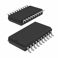
7. 封装信息: - SOIC JEDEC封装:74LCX374WM或74LCX374WMX,NS封装号M20B - SOIC EIAJ封装:74LCX374SJ或74LCX374SJX,NS封装号M20D - SSOP Type ll封装:74LCX374MSA或74LCX374MSAX,NS封装号MSA20 - TSSOP JEDEC封装:74LCX374MTC或74LCX374MTCX,NS封装号MTC20
74LCX374SJX 价格&库存

很抱歉,暂时无法提供与“74LCX374SJX”相匹配的价格&库存,您可以联系我们找货

免费人工找货