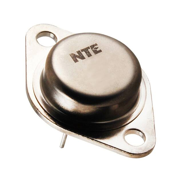
MJ10004
Silicon NPN Transistor
HV Darlington Power Amp, Switch
w/Base−Emitter Speedup Diode
TO−3 Type Package
Description:
The MJ10004 is a silicon NPN Darlington transistor in a TO−3 type package designed for high voltage,
high−speed, power switching in inductive circuits where fall−time is critical. It is particularly suited for
line operated switch−mode applications.
Applications:
D Switching Regulators
D Inverters
D Solenoid and Relay Drivers
D Motor Controls
Absolute Maximum Ratings:
Collector−Emitter Voltage, VCEV . . . . . . . . . . . . . . . . . . . . . . . . . . . . . . . . . . . . . . . . . . . . . . . . . . . . . 450V
Collector−Emitter Voltage, VCEX(sus) . . . . . . . . . . . . . . . . . . . . . . . . . . . . . . . . . . . . . . . . . . . . . . . . . 400V
Collector−Emitter Voltage, VCEO(sus) . . . . . . . . . . . . . . . . . . . . . . . . . . . . . . . . . . . . . . . . . . . . . . . . . 350V
Emitter−Base Voltage, VEBO . . . . . . . . . . . . . . . . . . . . . . . . . . . . . . . . . . . . . . . . . . . . . . . . . . . . . . . . . . 8V
Collector Current, IC
Continuous . . . . . . . . . . . . . . . . . . . . . . . . . . . . . . . . . . . . . . . . . . . . . . . . . . . . . . . . . . . . . . . . . . 20A
Peak . . . . . . . . . . . . . . . . . . . . . . . . . . . . . . . . . . . . . . . . . . . . . . . . . . . . . . . . . . . . . . . . . . . . . . . 30A
Base Current, IB . . . . . . . . . . . . . . . . . . . . . . . . . . . . . . . . . . . . . . . . . . . . . . . . . . . . . . . . . . . . . . . . . . 2.5A
Total Power Dissipation, PD
TC = +25C . . . . . . . . . . . . . . . . . . . . . . . . . . . . . . . . . . . . . . . . . . . . . . . . . . . . . . . . . . . . . . . . 175W
TC = +100C . . . . . . . . . . . . . . . . . . . . . . . . . . . . . . . . . . . . . . . . . . . . . . . . . . . . . . . . . . . . . . . 100W
Derate Above +25C . . . . . . . . . . . . . . . . . . . . . . . . . . . . . . . . . . . . . . . . . . . . . . . . . . . 1.0W/C
Operating Junction Temperature Range, TJ . . . . . . . . . . . . . . . . . . . . . . . . . . . . . . . . . . −65 to +200C
Storage Temperature Range, Tstg . . . . . . . . . . . . . . . . . . . . . . . . . . . . . . . . . . . . . . . . . . −65 to +200C
Thermal Resistance, Junction−to−Case, RthJC . . . . . . . . . . . . . . . . . . . . . . . . . . . . . . . . . . . . . 1.0C/W
Electrical Characteristics: (TC = +25C unless otherwise specified)
Parameter
Symbol
Test Conditions
Min
Typ
Max Unit
350
−
−
V
VCEV = 450V, VBE(off) = 1.5V
−
−
0.25
mA
VCEV = 450V, VBE(off) = 1.5V, TC = +100C
−
−
5.0
mA
ICER
VCE= 450V, RBE= 50, TC = +100C
−
−
5.0
mA
IEBO
VEB = 2V, IC = 0
−
−
175
mA
OFF Characteristics
Collector−Emitter Sustaining Voltage
Collector Cutoff Current
Emitter Cutoff Current
VCEO(sus) IC = 250mA, IB = 0, Vclamp = 350V
ICEV
�Electrical Characteristics (Cont’d): (TC = +25C unless otherwise specified)
Parameter
Symbol
Test Conditions
Min
Typ
Max Unit
VCE = 5V, IC = 5A
50
−
600
VCE = 5V, IC = 10A
40
−
400
IC = 10A, IB = 400mA
−
−
1.9
V
IC = 10A, IB = 400mA, TC = +100C
−
−
2.0
V
IC = 20A, IB = 2A
−
−
3.0
V
IC = 10A, IB = 400mA
−
−
2.5
V
IC = 10A, IB = 400mA, TC = +100C
−
−
2.5
V
VF
IF = 10A
−
−
5.0
V
Small−Signal Current Gain
|hfe|
VCE = 10V, IC = 1A, ftest = 1MHz, Note 2
10
−
−
Output Capacitance
Cob
VCB = 10V, IE = 0, ftest = 100kHz
100
−
−
pF
−
−
0.2
s
−
−
0.6
s
ON Characteristics (Note 1)
DC Current Gain
Collector−Emitter Saturation Voltage
Base−Emitter Saturation Voltage
hFE
VCE(sat)
VBE(sat)
Diode Forward Voltage
Dynamic Characteristics
Switching Characteristics
Delay Time
td
Rise Time
tr
Storage Time
ts
−
−
1.5
s
Fall Time
tf
−
−
0.5
s
VCC = 250V, IC = 10A, IB1 = 400mA,
VBE(off) = 5V, tp = 50s, Duty Cycle 2%
Note 1. Pulse test: Pulse Width = 300s, Duty Cycle 2%.
Note 2. fT = |hfe| ftest
.135 (3.45) Max
.350 (8.89)
.875 (22.2)
Dia Max
Seating
Plane
C
B
.312 (7.93) Min
E
Emitter
.040 (1.02)
1.187 (30.16)
.665
(16.9)
.215 (5.45)
.156 (3.96) Dia
(2 Holes)
.430
(10.92)
.188 (4.8) R Max
Base
.525 (13.35) R Max
Collector/Case
�
很抱歉,暂时无法提供与“MJ10004”相匹配的价格&库存,您可以联系我们找货
免费人工找货