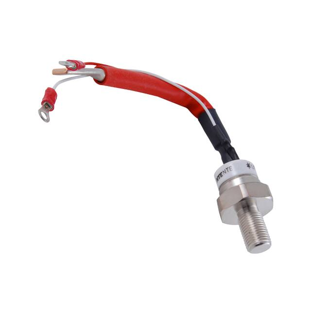
NTE5570, NTE5572, & NTE5574
Silicon Controlled Rectifier (SCR)
125 Amp, TO94
Electrical Characteristics: (Maximum values @ TJ = +125°C unless otherwise specified)
Repetitive Peak Voltages, VDRM & VRRM
NTE5570 . . . . . . . . . . . . . . . . . . . . . . . . . . . . . . . . . . . . . . . . . . . . . . . . . . . . . . . . . . . . . . . . . . . 200V
NTE5572 . . . . . . . . . . . . . . . . . . . . . . . . . . . . . . . . . . . . . . . . . . . . . . . . . . . . . . . . . . . . . . . . . . . 600V
NTE5574 . . . . . . . . . . . . . . . . . . . . . . . . . . . . . . . . . . . . . . . . . . . . . . . . . . . . . . . . . . . . . . . . . . 1200V
Non−Repetitive Peak Reverse Blocking Voltage, VRSM
NTE5570 . . . . . . . . . . . . . . . . . . . . . . . . . . . . . . . . . . . . . . . . . . . . . . . . . . . . . . . . . . . . . . . . . . . 500V
NTE5572 . . . . . . . . . . . . . . . . . . . . . . . . . . . . . . . . . . . . . . . . . . . . . . . . . . . . . . . . . . . . . . . . . . . 900V
NTE5574 . . . . . . . . . . . . . . . . . . . . . . . . . . . . . . . . . . . . . . . . . . . . . . . . . . . . . . . . . . . . . . . . . . 1300V
Average On−State Current (Half Sine Wave, 180°, TC = +85°C), IT(AV) . . . . . . . . . . . . . . . . . . . . 80A
RMS On−State Current (DC @ TC = +75°C), IT(RMS) . . . . . . . . . . . . . . . . . . . . . . . . . . . . . . . . . . . 125A
Peak One−Cycle, Non−Repetitive Surge Current (10ms Duration, Sinusoidal Half Wave), ITSM
No Voltage Reapplied . . . . . . . . . . . . . . . . . . . . . . . . . . . . . . . . . . . . . . . . . . . . . . . . . . . . . . . 1900A
100% VRRM Reapplied . . . . . . . . . . . . . . . . . . . . . . . . . . . . . . . . . . . . . . . . . . . . . . . . . . . . . . 1600A
Maximum I2t for Fusing (10ms Duration, Sinusoidal Half Wave), I2t
No Voltage Reapplied . . . . . . . . . . . . . . . . . . . . . . . . . . . . . . . . . . . . . . . . . . . . . . . . . 18000A2sec
100% VRRM Reapplied . . . . . . . . . . . . . . . . . . . . . . . . . . . . . . . . . . . . . . . . . . . . . . . . 12700A2sec
Peak Positive Gate Current (5ms Pulse Width), IGM . . . . . . . . . . . . . . . . . . . . . . . . . . . . . . . . . . . . . . 3A
Peak Positive Gate Voltage (5ms Pulse Width), +VGM . . . . . . . . . . . . . . . . . . . . . . . . . . . . . . . . . . . 20V
Peak Negative Gate Voltage (5ms Pulse Width), −VGM . . . . . . . . . . . . . . . . . . . . . . . . . . . . . . . . . . 10V
Average Gate Power (f = 50Hz, Duty Cycle = 50%), PG . . . . . . . . . . . . . . . . . . . . . . . . . . . . . . . . . 3W
Peak Gate Power (50ms Pulse Width), PGM . . . . . . . . . . . . . . . . . . . . . . . . . . . . . . . . . . . . . . . . . . 12W
Rate of Rise of Off−State Voltage (Exponential to 67% Rated VDRM), dv/dt . . . . . . . . . . . . . 500V/μs
Rate of Rise of ON−State Current, di/dt
(Gate Drive 20V, 65Ω, with tr = 0.5μs, Vd = Rated VDRM, ITM = 2 x di/dt snubber 0.2μF)
Non−Repetitive . . . . . . . . . . . . . . . . . . . . . . . . . . . . . . . . . . . . . . . . . . . . . . . . . . . . . . . 300A/μs
Typical Delay Time, td
(Gate Pulse: 10V, 15Ω Source, tp = 6μs, tr = 0.1μs, Vd = rated VDRM, ITM = 50A) . . . . . . 1μs
Typical Turn−On Time, tq
(ITM = 50A, di/dt = −5A/μs min, VR = 50V, dv/dt = 20V/μs, Gate Bias: 0V 25Ω, tp = 500μs) 110μs
On−State Voltage (IPk = 250A, 10ms Sine Pulse), VTM . . . . . . . . . . . . . . . . . . . . . . . . . . . . . . . . . 1.6V
Repetitive Peak Off−State Current (At VDRM), IDRM . . . . . . . . . . . . . . . . . . . . . . . . . . . . . . . . . . . 15mA
Repetitive Peak Reverse Current (At VRRM), IRRM . . . . . . . . . . . . . . . . . . . . . . . . . . . . . . . . . . . . 15mA
Maximum Gate Current Required to Trigger, IGT
(6V Anode−to−Cathode Applied, TJ = +25°C) . . . . . . . . . . . . . . . . . . . . . . . . . . . . . . . . . 120mA
Maximum Gate Voltage Required to Trigger, VGT
(6V Anode−to−Cathode Applied, TJ = +25°C) . . . . . . . . . . . . . . . . . . . . . . . . . . . . . . . . . . . 2.5V
Maximum Holding (Anode Supply 12V Resistive Load, TJ = +25°C), IH . . . . . . . . . . . . . . . . . 150mA
Maximum Gate Voltage which will not Trigger any Device, VGD . . . . . . . . . . . . . . . . . . . . . . . . . 0.25V
�Electrical Characteristics (Cont’d): (Maximum values @ TJ = +125°C unless otherwise specified)
Operating Temperature Range, TJ . . . . . . . . . . . . . . . . . . . . . . . . . . . . . . . . . . . . . . . . . . −40° to +125°C
Storage Temperature Range, Tstg . . . . . . . . . . . . . . . . . . . . . . . . . . . . . . . . . . . . . . . . . . −40° to +150°C
Thermal Resistance, Junction−to−Case (DC Operation), RtnJC . . . . . . . . . . . . . . . . . . . . . . . 0.3°C/W
Thermal Resistance, Case−to−Heat Sink, RthC−HS
(Mounting Surface Smooth, Flat, and Greased) . . . . . . . . . . . . . . . . . . . . . . . . . . . . . . 0.1°C/W
1.227 (31.18) Max
(Across Corners)
ÇÇ
ÇÇ
ÇÇ
.875 (22.22) Dia
(Ceramic)
For No. 6 Screw
Cathode
.280 (7.11)
Dia Max
Gate
(White)
7.500
Cathode
(190.5)
(Red)
Max
(Terminals 1 & 2)
6.260
(159.0)
Max
(Terminal 3)
2.500
(63.5)
Max
1.031 (26.18)
Dia Max
Seating Plane
.827
(27.0)
Max
.500 (12.7) Max)
1/2−20 UNF
Anode
�