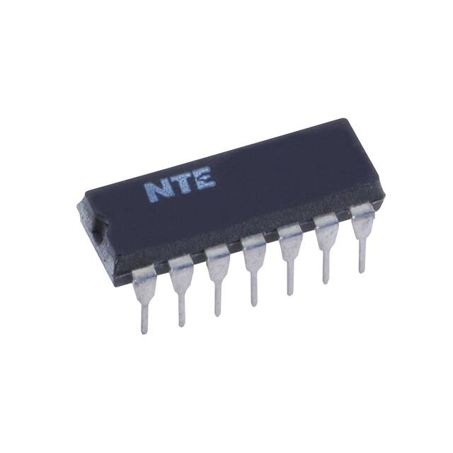
NTE74LS07
Integrated Circuit
TTL − Hex Buffer/Driver
with Open Collector High Voltage Outputs
Description:
The NTE74LS07 is a hex buffer/driver in a 14−Lead plastic DIP type package that features high
voltage open collector outputs to interface with high level circuits (such as MOS), or for driving high
current loads, and also is characterized for use as a buffer for driving TTL inputs.
This device is compatible with most TTL families. Inputs are diode−clamped to minimize transmission
effects, which simplifies design. Typical power dissipation is 140mW, and average propagation delay
time is 12ns.
Features:
D Converts TTL Voltage Levels to MOS Levels
D High Sink−Current Capability
D Input Clamping Diodes Simplify System Design
D Open−Collector Driver for Indicator Lamps and Relays
D Inputs Fully Compatible with Most TTL Circuits
Absolute Maximum Ratings: (Note 1)
Supply Voltage, VCC . . . . . . . . . . . . . . . . . . . . . . . . . . . . . . . . . . . . . . . . . . . . . . . . . . . . . . . . . . . . . . . . . 7V
DC Input Voltage, VIN . . . . . . . . . . . . . . . . . . . . . . . . . . . . . . . . . . . . . . . . . . . . . . . . . . . . . . . . . . . . . . . . 7V
Output Voltage (Note 2), VO . . . . . . . . . . . . . . . . . . . . . . . . . . . . . . . . . . . . . . . . . . . . . . . . . . . . . . . . . 30V
Operating Temperature Range, TA . . . . . . . . . . . . . . . . . . . . . . . . . . . . . . . . . . . . . . . . . . . . 0C to +70C
Storage Temperature Range, Tstg . . . . . . . . . . . . . . . . . . . . . . . . . . . . . . . . . . . . . . . . −65C to +150C
Note 1. Unless otherwise specified, all voltages are referenced to GND.
Note 2. This is the maximum voltage that should be applied to any output when it is in the off state.
Recommended Operating Conditions:
Parameter
Symbol
Min
Typ
Max
Unit
Supply Voltage
VCC
4.75
5.0
5.25
V
High−Level Input Voltage
VIH
2.0
−
−
V
Low−Level Input Voltage
VIL
−
−
0.8
V
High−Level Output Voltage
VOH
−
−
30
V
Low−Level Output Current
IOL
−
−
40
mA
Operating Temperature Range
TA
0
−
+70
C
�Electrical Characteristics: (Note 3, Note 4)
Parameter
Symbol
Test Conditions
Min
Typ
Max
Unit
Input Clamp Voltage
VIK
VCC = MIN, II = −12mA
−
−
−1.5
V
High Level Output Current
IOH
VCC = MIN, VIH = 2V, VOH = 30V
−
−
0.25
mA
Low Level Output Voltage
VOL
VCC = MIN, VIL = 0.8V, IOL = 16mA
−
−
0.4
V
VCC = MIN, VIL = 0.8V, IOL = 40mA
−
−
0.7
V
Input Current
II
VCC = MAX, VI = 7V
−
−
1
mA
High Level Input Current
IIH
VCC = MAX, VI = 2.4V
−
−
20
A
Low Level Input Current
IIL
VCC = MAX, VI = 0.4V
−
−
−0.2
mA
High Level Supply Current
ICCH
VCC = MAX
−
−
14
mA
Low Level Supply Current
ICCL
VCC = MAX
−
−
45
mA
Note 3. .For conditions shown as MIN or MAX, use the appropriate value specified under “Recommended
Operation Conditions”.
Note 4. All typical values are at VCC = 5V, TA = +25C.
Switching Characteristics: (VCC = 5V, TA = +25C unless otherwise specified)
Parameter
Propagation Delay Time
From A Input to Y Output)
Symbol
tPLH
Test Conditions
RL = 110, CL = 15pF
tPHL
Pin Connection Diagram
1A 1
14 VCC
1Y 2
2A 3
13 6A
12 6Y
2Y 4
11 5A
3A 5
10 5Y
3Y 6
9 4A
GND 7
8 4Y
Min
Typ
Max
Unit
−
6
10
ns
−
19
30
ns
�14
8
1
7
.300 (7.62)
.785 (19.95) Max
.200
(5.08)
Max
.100 (2.45)
.600 (15.24)
.099 (2.5) Min
�
很抱歉,暂时无法提供与“NTE74LS07”相匹配的价格&库存,您可以联系我们找货
免费人工找货- 国内价格
- 1+28.86840
- 200+11.52360
- 500+11.13480
- 1000+10.95120
