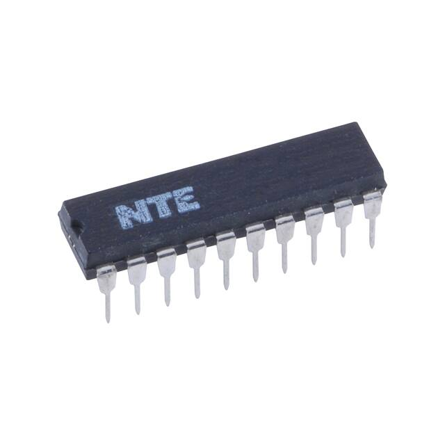
NTE74LS377
Integrated Circuit
TTL − Octal D−Type Flip−Flop with Enable
Description:
The NTE74LS377 is a hex monolithic, positive−edge−triggered flip−flop in a 20−Lead plastic DIP type
package that utilizes TTL circuitry to implement D−type flip−flop logic with an enable input. The
NTE74LS377 is similar to the NTE74LS173 but features a common enable instead of a common
clear.
Information at the D inputs meeting the setup time requirements is transferred to the Q outputs on
the positive−going edge of the clock pulse if the enable input G is low. Clock triggering occurs at a
particular voltage level and is not directly related to the transition time of the positive−going pulse.
When the clock input is at either the high or ,low level, the D input signal has no effect a the output.
The circuit is designed to prevent false clocking by transitions at the G input.
The flip−flops are guaranteed to respond to clock frequencies ranging from 0 to 30Mhz while maximum clock frequency is typically 40Mhz. Typical power dissipation is 10mW per flip−flop.
Features:
D Contains Eight Flip−Flops with Single Rail Outputs
D Individual Data Input to Each Flip−Flop
Applications:
D Buffer/Storage Registers
D Shift Registers
D Pattern Generators
Absolute Maximum Ratings: (Note 1)
Supply Voltage, VCC . . . . . . . . . . . . . . . . . . . . . . . . . . . . . . . . . . . . . . . . . . . . . . . . . . . . . . . . . . . . . . . . . 7V
DC Input Voltage, VIN . . . . . . . . . . . . . . . . . . . . . . . . . . . . . . . . . . . . . . . . . . . . . . . . . . . . . . . . . . . . . . . . 7V
Operating Temperature Range, TA . . . . . . . . . . . . . . . . . . . . . . . . . . . . . . . . . . . . . . . . . . . . 0C to +70C
Storage Temperature Range, Tstg . . . . . . . . . . . . . . . . . . . . . . . . . . . . . . . . . . . . . . . . −65C to +150C
Note 1. Unless otherwise specified, all voltages are referenced to GND.
�Recommended Operating Conditions:
Parameter
Symbol
VCC
IOH
IOL
fclock
tw
tsu
Supply Voltage
High−Level Output Current
Low−Level Output Current
Clock Frequency
Width of Clock Pulse
Setup Time
Data Input
Enable Active−State
Enable Inactive−State
Hold Time
Operating Temperature Range
th
TA
Min
4.75
−
−
0
20
Typ
5.0
−
−
−
−
20
25
10
5
0
−
−
−
−
−
Max Unit
5.25
V
−400 A
8
mA
30
MHz
−
ns
−
−
−
−
+70
ns
ns
ns
ns
C
Electrical Characteristics: (Note 2, Note 3)
Parameter
Symbol
High Level Input Voltage
Test Conditions
VIH
Min
Typ
Max
Unit
2
−
−
V
−
−
0.8
V
−
−
−1.5
V
2.7
3.5
Low Level Input Voltage
VIL
Input Clamp Voltage
VIK
VCC = MIN, II = −18mA
High Level Output Voltage
VOH
VCC = MIN, VIH = 2V, VIL = MAX, IOH = -400A
Low Level Output Voltage
VOL
VCC = MIN, VIH = 2V, VIL = MAX IOL = 4mA
−
0.25
0.4
V
IOL = 8mA
−
0.35
0.5
V
V
Input Current
II
VCC = MAX, VI = 7V
−
−
0.1
mA
High Level Input Current
IIH
VCC = MAX, VI = 2.7V
−
−
20
A
Low Level Input Current
IIL
VCC = MAX, VI = 0.4V
−
−
−0.4
mA
Short−Circuit Output Current
IOS
VCC = MAX, Note 4
−20
−
−100
mA
Supply Current
ICC
VCC = MAX, Note 5
−
17
28
mA
Note 2. .For conditions shown as MIN or MAX, use the appropriate value specified under “Recommended
Operation Conditions”.
Note 3. All typical values are at VCC = 5V, TA = +25C.
Note 4. Not more than one output should be shorted at a time, and duration of the short−circuit
should not exceed one second.
Note 4. With all outputs open and ground applied to all data inputs, ICC is measured after a momentary ground, then 4.5V is applied to the clock.
Switching Characteristics: (VCC = 5V, TA = +25C unless otherwise specified)
Parameter
Maximum Clock Frequency
Symbol
fmax
Propagation Delay Time, from Clock
G
H
L
L
X
Test Conditions
RL = 2k, CL = 15pF
Min
Typ
Max
Unit
30
40
−
MHz
tPLH
−
17
27
ns
tPHL
−
18
27
ns
Function Table (Each Flip−Flop):
Inputs
Outputs
Clock
Data
Q
Q
X
X
Q0
Q0
H
H
L
L
L
H
L
X
Q0
Q0
�Pin Connection Diagram
G 1
20 VCC
1Q 2
1D 3
19 8Q
18 8D
2D 4
17 7D
2Q 5
16 7Q
3Q 6
3D 7
15 6Q
14 6D
4D 8
13 5D
4Q 9
12 5Q
GND 10
11 CLK
20
11
1
10
.300 (7.62)
1.200 (30.5) Max
.260 (6.6)
Max
.200
(5.08)
Max
.100 (2.54)
Min
.012
(0.30)
.100 (2.54) Typ
.350 (8.89)
�
很抱歉,暂时无法提供与“NTE74LS377”相匹配的价格&库存,您可以联系我们找货
免费人工找货