Freescale Semiconductor, Inc.
MOTOROLA
Order number: MC100ES60T22
Rev 1, 5/2004
SEMICONDUCTOR TECHNICAL DATA
MC100ES60T22
3.3V Dual LVTTL/LVCMOS to
Differential LVPECL Translator
The MC100ES60T22 is a low skew dual LVTTL/LVCMOS to differential
LVPECL translator. The low voltage PECL levels, small package, and dual
gate design are ideal for clock translation applications.
Freescale Semiconductor, Inc...
Features
•
•
•
•
•
280 ps typical propagation delay
100 ps max output-to-output skew
LVPECL operating range: VCC = 3.135 V to 3.8 V
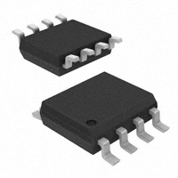
8-lead SOIC package
Ambient temperature range –40°C to +85°C
D SUFFIX
8 LEAD SOIC PACKAGE
CASE 751
ORDERING INFORMATION
Device
Q0
Q0
1
8
2
7
LVPECL
Q1
Q1
3
4
VCC
D0
LVTTL/LVCMOS
6
5
D1
Package
MC100ES60T22D
SO-8
MC100ES60T22DR2
SO-8
PIN DESCRIPTION
Pin
Function
D0, D1
LVTTL/LVCMOS Inputs
Qn, Qn
LVPECL Differential Outputs
VCC
Positive Supply
GND
Negative Supply
GND
Figure 1. 8-Lead Pinout (Top View) and Logic Diagram
© Motorola, Inc. 2004
For More Information On This Product,
Go to: www.freescale.com
�Freescale Semiconductor, Inc.
MC100ES60T22
Table 1. General Specifications
Characteristics
Value
Internal Input Pulldown Resistor
75 kΩ
Internal Input Pullup Resistor
75 kΩ
ESD Protection
Human Body Model
Machine Model
> 2000 V
> 200 V
θJA Thermal Resistance (Junction-to-Ambient)
0 LFPM, 8 SOIC
500 LFPM, 8 SOIC
190°C/W
130°C/W
Meets or exceeds JEDEC Spec EIA/JESD78 IC Latchup Test
Table 2. Absolute Maximum Ratings1
Freescale Semiconductor, Inc...
Symbol
Rating
Conditions
Rating
Units
3.9
V
VCC + 0.3
VEE – 0.3
V
V
50
100
mA
mA
VSUPPLY
Power Supply Voltage
Difference between VCC & VEE
VIN
Input Voltage
VCC – VEE ≤ 3.6 V
Iout
Output Current
Continuous
Surge
TA
Operating Temperature Range
–40 to +85
°C
TSTG
Storage Temperature Range
–65 to +150
°C
1. Absolute maximum continuous ratings are those maximum values beyond which damage to the device may occur. Exposure to these conditions
or conditions beyond those indicated may adversely affect device reliability. Functional operation at absolute-maximum-rated conditions is not
implied.
Table 3. DC Characteristics (VCC = 3.135 V to 3.8 V; VEE = 0 V)
Symbol
–40°C
Characteristic
Min
Typ
0°C to 85°C
Max
Min
Typ
17
Max
Unit
22
mA
VCC – 750
mV
VCC – 1950 VCC – 1620 VCC – 1250 VCC – 2000 VCC – 1680 VCC – 1300
mV
IGND
Power Supply Current
VOH1
Output HIGH Voltage
VCC – 1150 VCC – 1020
VOL1
Output LOW Voltage
VCC – 800
VCC – 1200
VCC – 970
1. Outputs are terminated through a 50 Ω resistor to VCC – 2 volts
Table 4. LVTTL / LVCMOS Input DC Characteristics (VCC = 3.135 V to 3.8 V)
Symbol
Characteristic
Condition
–40°C
Min
Typ
0°C to 85°C
Max
Min
Typ
Max
Unit
IIN
Input Current
VIN = VCC
±150
±150
µA
VIK
Input Clamp Voltage
IIN = –18 mA
–1.2
–1.2
V
VIH
Input HIGH Voltage
VCC+0.3
V
VIL
Input LOW Voltage
0.8
V
MOTOROLA
2.0
VCC+0.3
2.0
0.8
2
For More Information On This Product,
Go to: www.freescale.com
TIMING SOLUTIONS
�Freescale Semiconductor, Inc.
MC100ES60T22
Table 5. AC Characteristics (VCC = 3.134 V to 3.8 V; VEE = 0 V)
Symbol
–40°C
Characteristic
Min
fmax
Maximum Toggle Frequency
tPLH, tPHL
Propagation Delay
tSKEW
Skew
tJITTER
Cycle-to-Cycle Jitter
VoutPP
Output Peak-to-Peak Voltage
350
tr / tf
Output Rise/Fall Times (20% – 80%)
50
25°C
Typ
Max
Min
Typ
85°C
Max
1
100
260
Min
Typ
1
400
100
280
400
100
280
Max
Unit
1
GHz
450
ps
part-to-part
300
300
350
ps
RMS (1σ)
1
1
1
ps
750
350
400
750
50
350
400
50
750
mV
400
ps
Freescale Semiconductor, Inc...
Figure 1.
Q
D
Driver
Device
Receiver
Device
Qb
Db
50Ω
50Ω
V TT
Figure 2. Typical Termination for Output Driver and Device Evaluation
TIMING SOLUTIONS
3
For More Information On This Product,
Go to: www.freescale.com
MOTOROLA
�Freescale Semiconductor, Inc.
OUTLINE DIMENSIONS
SOIC-8
D SUFFIX
8-LEAD SOIC PACKAGE
CASE 751-06
ISSUE T
D
A
8
NOTES:
1. DIMENSIONING AND TOLERANCING PER ASME
Y14.5M, 1994.
2. DIMENSIONS ARE IN MILLIMETER.
3. DIMENSION D AND E DO NOT INCLUDE MOLD
PROTRUSION.
4. MAXIMUM MOLD PROTRUSION 0.15 PER SIDE.
5. DIMENSION B DOES NOT INCLUDE DAMBAR
PROTRUSION. ALLOWABLE DAMBAR
PROTRUSION SHALL BE 0.127 TOTAL IN EXCESS
OF THE B DIMENSION AT MAXIMUM MATERIAL
CONDITION.
C
5
0.25
H
E
M
B
M
1
Freescale Semiconductor, Inc...
4
h
B
X 45˚
e
θ
A
C
SEATING
PLANE
L
0.10
A1
B
0.25
M
C B
S
STYLE 1:
PIN 1 EMITTER
A
S
STYLE 2:
PIN 1 COLLECTOR DIE #1
STYLE 3:
PIN 1 DRAIN DIE #1
DIM
A
A1
B
C
D
E
e
H
h
L
q
MILLIMETERS
MIN
MAX
1.35
1.75
0.10
0.25
0.35
0.49
0.19
0.25
4.80
5.00
3.80
4.00
1.27 BSC
5.80
6.20
0.25
0.50
0.40
1.25
0˚
7˚
STYLE 4:
PIN 1 ANODE
Information in this document is provided solely to enable system and software implementers to use Motorola products. There are no express or implied
copyright licenses granted hereunder to design or fabricate any integrated circuits or integrated circuits based on the information in this document.
Motorola reserves the right to make changes without further notice to any products herein. Motorola makes no warranty, representation or guarantee
regarding the suitability of its products for any particular purpose, nor does Motorola assume any liability arising out of the application or use of any product
or circuit, and specifically disclaims any and all liability, including without limitation consequential or incidental damages. “Typical” parameters which may be
provided in Motorola data sheets and/or specifications can and do vary in different applications and actual performance may vary over time. All operating
parameters, including “Typicals” must be validated for each customer application by customer’s technical experts. Motorola does not convey any license
under its patent rights nor the rights of others. Motorola products are not designed, intended, or authorized for use as components in systems intended for
surgical implant into the body, or other applications intended to support or sustain life, or for any other application in which the failure of the Motorola product
could create a situation where personal injury or death may occur. Should Buyer purchase or use Motorola products for any such unintended or
unauthorized application, Buyer shall indemnify and hold Motorola and its officers, employees, subsidiaries, affiliates, and distributors harmless against all
claims, costs, damages, and expenses, and reasonable attorney fees arising out of, directly or indirectly, any claim of personal injury or death associated
with such unintended or unauthorized use, even if such claim alleges that Motorola was negligent regarding the design or manufacture of the part.
MOTOROLA and the Stylized M Logo are registered in the US Patent and Trademark Office. All other product or service names are the property of their
respective owners.
© Motorola, Inc. 2004
HOW TO REACH US:
USA/EUROPE/LOCATIONS NOT LISTED:
Motorola Literature Distribution
P.O. Box 5405, Denver, Colorado 80217
1-800-521-6274 or 480-768-2130
JAPAN: Motorola Japan Ltd.; SPS, Technical Information Center
3-20-1 Minami-Azabu. Minato-ku, Tokyo 106-8573, Japan
81-3-3440-3569
ASIA/PACIFIC: Motorola Semiconductors H.K. Ltd.; Silicon Harbour Centre
2 Dai King Street, Tai Po Industrial Estate, Tai Po, N.T., Hong Kong
852-26668334
HOME PAGE: http://motorola.com/semiconductors
MC100ES60T22
For More Information On This Product,
Go to: www.freescale.com
�


 工商网监
湘ICP备2023018690号
工商网监
湘ICP备2023018690号
