Freescale Semiconductor
Technical Data
Document Number: MC34844
Rev. 10.0, 8/2014
10 Channel LED Backlight Driver
with Integrated Power Supply
34844
The 34844 is a SMARTMOS high efficiency, LED driver for use in
backlighting LCD displays from 10" to 20"+. Operating from supplies of 7.0 to
28 V, the MC34844 is capable of driving up to 160 LEDs in 10 parallel strings.
Current in the 10 strings is matched to within 2%, and can be programmed via
the I2C/SM Bus interface.
The 34844 also includes a Pulse Width Monitor (PWM) generator for LED
dimming. The LEDs can be dimmed to one of 256 levels, programmed through
the I2C/SM Bus interface. Up to 65,000:1 (256:1 PWM, 256:1 Current DAC)
dimming ratio.
The integrated boost converter generates the minimum output voltage
required to keep all LEDs illuminated with the selected current, providing the
highest efficiency possible.
The 34844 has an integrated boost self-clock at a default frequency of
600 kHz, but may be programmed via I2C to 150/300/600/1200 kHz. The PWM
frequency can be set from 100 Hz to 25 kHz, or can be synchronized to an
external input. If not synchronized to another source, the internal PWM rate
outputs on the CK pin. This enables multiple devices to be synchronized
together.
The 34844 has a default boost frequency of 320 kHz, but may be
programmed via I2C to 160/320/650/1300 kHz. The PWM frequency can be set
from 110 Hz to 27 kHz, or can be synchronized to an external input. If not
synchronized to another source, the internal PWM rate outputs on the CK pin.
This enables multiple devices to be synchronized together.
The 34844 also supports optical/temperature closed loop operation and
features LED overtemperature protection, LED short protection, and LED open
circuit protection. The IC includes overvoltage protection, overcurrent
protection, and undervoltage lockout.
Features
•
•
•
•
•
•
•
•
•
Input voltage of 7.0 to 28 V
2.5 A integrated boost FET
Up to 80 mA on the 34844 LED current per channel
90% efficiency (DC:DC)
I2C/SM Bus interface
10 channel current mirror with ±2.0% current matching
Boost output voltage up to 60V, with Dynamic Headroom Control (DHC)
PWM frequency programmable or synchronizable from 110 to 27,000 Hz
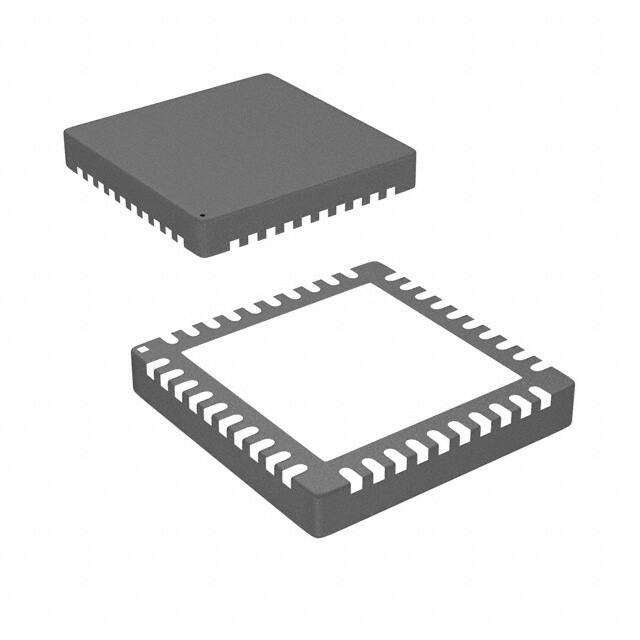
32-Ld 5x5x1.0 mm TQFN Package
© Freescale Semiconductor, Inc., 2009-2014. All rights reserved.
LED DRIVER
EP SUFFIX (PB-FREE)
98ASA10800D
32-PIN QFN-EP
Applications
•
•
•
•
Monitors and HDTV - up to 42 inch
Personal Computer Notebooks
GPS Screens
Small screen Televisions
�34844
VIN
VDC1
VDC2
7.0 to 28 V
SWA
SWB
VOUT
VDC3
PGNDA
COMP
PGNDB
SLOPE
Control Unit
VDC1
VDC1
FAIL
SCK
SDA
A0/SEN
CK
ISET
PIN
NIN
~
~
~
~
~
~
~
~
~
~
I0
I1
I2
I3
I4
I5
I6
I7
I8
I9
PWM
M/~S
EN
VDC1
VCC
GND
Figure 1. MC34844 Simplified Application Diagram (SM Bus Mode)
34844
VIN
7.0 to 28V
SWA
SWB
VDC1
VDC2
PWM
PGNDA
COMP
PGNDB
SLOPE
Control Unit
FAIL
SCK
SDA
PWM
PWM
VOUT
VDC1
A0/SEN
CK
M/~S
EN
VDC1
ISET
PIN
NIN
VOUT
VOUT
VDC3
GND
VCC
~
~
~
~
~
~
~
~
~
~
I0
I1
I2
I3
I4
I5
I6
I7
I8
I9
Figure 2. MC34844 Simplified Application Diagram (Manual Mode)
34844
2
Analog Integrated Circuit Device Data
Freescale Semiconductor
�ORDERABLE PARTS
ORDERABLE PARTS
This section describes the part numbers available to be purchased along with their differences. Valid orderable part numbers are provided
on the web. To determine the orderable part numbers for this device, go to http://www.freescale.com and perform a part number search for
the following device numbers.
Table 1. Orderable Part Variations
Part Number
MC34844AEP
Notes
Temperature (TA)
(1)
-40 to 105 °C
Package
32 QFN-EP
Notes:
1. To order parts in Tape & Reel, add the R2 suffix to the part number.
34844
Analog Integrated Circuit Device Data
Freescale Semiconductor
3
�INTERNAL BLOCK DIAGRAM
INTERNAL BLOCK DIAGRAM
SWA
VIN
VDC1
VDC2
SWB
LDO
A0/SEN
OVP
VDC3
PGNDA
COMP
SLOPE
BOOST
CONTROLLER
PGNDB
VOUT
CK
EN
CLOCK/PLL
V SENSE
FAIL
M/~S
PWM
I0
PWM GENERATOR
I1
I2
SCK
SDA
I2C INTERFACE
10 CHANNEL
80 mA CURRENT
MIRROR
I3
I4
I5
I6
I7
I8
ISET
CURRENT DAC
PIN
TEMP/OPTO
LOOP CONTROL
NIN
I9
OCP/OTP/UVLO
GND
Figure 3. 34844 Simplified Internal Block Diagram
34844
4
Analog Integrated Circuit Device Data
Freescale Semiconductor
�PIN CONNECTIONS
VDC2
M/~S
COMP
VDC1
SCK
SDA
PWM
Transparent Top View
VOUT
PIN CONNECTIONS
32
31
30
29
28
27
26
25
VIN 1
24 CK
PGNDB 2
23 VDC3
TRANSPARENT
TOP VIEW
SWB 3
SWA 4
22 SLOPE
QFN - EP
5MM X 5MM
32 LEAD
PGNDA 5
21 NIN
20 PIN
EP GND
A0/SEN 6
19 ISET
EN 7
18 FAIL
IO 8
EP = Exposed Pad
17 I9
9
10
11
12
13
14
15
16
I1
I2
I3
I4
I5
I6
I7
I8
Figure 4. 34844 Pin Connections
A functional description of each pin can be found in the Functional Pin Description section beginning on page 13.
Table 2. 34844 Pin Definitions
Pin Number
Pin Name
Pin Function
Formal Name
Definition
1
VIN
Power
Input voltage
2
PGNDB
Power
Power Ground
Power ground
3
SWB
Input
Switch node B
Boost switch connection B
4
SWA
Input
Switch node A
Boost switch connection A
5
PGNDA
Power
Power Ground
Power ground
6
A0/SEN
Input
Device Select
Address select, device select pin or OVP HW control
7
EN
Input
Enable
8 - 17
I0-I9
Input
LED Channel
18
FAIL
Open Drain
Fault detection
19
ISET
Passive
Current set
20
PIN
Input
Positive current scale
21
NIN
Input
Negative current scale Negative input analog current control
22
SLOPE
Passive
Boost Slope
23
VDC3
Output
Internal Regulator 3
24
CK
Input/Output
Clock signal
25
PWM
Input
External PWM
Input supply
Enable pin (active high, internal pull-up)
LED string connections
Fault detected pin (open drain):
No Failure = low-impedance
Failure = high-impedance
LED current setting resistor
Positive input analog current control
Boost slope compensation setting resistor
Decoupling capacitor for internal phase locked loop power
Clock synchronization pin (input for M/~S = low - internal pull-up, output for
M/~S = high)
External PWM input (internal pull-down)
34844
Analog Integrated Circuit Device Data
Freescale Semiconductor
5
�PIN CONNECTIONS
Table 2. 34844 Pin Definitions (continued)
Pin Number
Pin Name
Pin Function
Formal Name
Definition
2
26
SDA
Bidirectional
I2C data
I C data line
27
SCK
Bidirectional
I2C clock
I2C clock line
28
VDC1
Output
Internal Regulator 1
29
COMP
Passive
Compensation pin
30
M/~S
Input
Master/Slave selector
Selects Master mode (1) or Slave mode (0)
31
VDC2
Output
Internal Regulator 2
Decoupling capacitor for internal regulator
32
VOUT
Input
Voltage Output
EP
GND
-
Ground
Decoupling capacitor for internal logic rail
Boost converter type compensation pin
Boost output voltage sense pin
Ground reference for all internal circuits other than boost FET
34844
6
Analog Integrated Circuit Device Data
Freescale Semiconductor
�ELECTRICAL CHARACTERISTICS
MAXIMUM RATINGS
ELECTRICAL CHARACTERISTICS
MAXIMUM RATINGS
Table 3. Maximum Ratings
All voltages are with respect to ground unless otherwise noted. Exceeding these ratings may cause a malfunction or permanent damage
to the device.
Symbol
Ratings
Value
Unit
Notes
V
(5)
ELECTRICAL RATINGS
VMAX
Maximum Pin Voltages
A0/SEN
I0, I1, I2, I3, I4, I5, I6, I7, I8, I9
EN, VIN
SWA, SWB, VOUT
FAIL, PIN, NIN, ISET, M/~S, CK, PWM
7.0
45
30
65
6.0
IMAX
Maximum LED Current
85
mA
VESD
ESD Voltage
Human Body Model (HBM)
Machine Model (MM)
+2000
+200
V
-40 to 105
°C
(2)
THERMAL RATINGS
TA
Ambient Temperature Range
TJA
Junction to Ambient Temperature
32
°C/W
(3)
TJC
Junction to Case Temperature
3.5
°C/W
(3)
TJ
Maximum junction temperature
150
°C
-40 to 150
°C
°C
TSTO
Storage temperature range
TPPRT
Peak Package Reflow Temperature During Reflow
260
Power Dissipation
TA = 25 °C
TA = 70 °C
TA = 85 °C
TA = 105 °C
3.9
2.5
2.0
1.4
(4)
W
Notes
2. ESD testing is performed in accordance with the Human Body Model (HBM) (AEC-Q100-2), and the Machine Model (MM) (AEC-Q100-003),
RZAP = 0
3.
4.
5.
Per JEDEC51 Standard for Multilayer PCB
Pin soldering temperature limit is for 10 seconds maximum duration. Not designed for immersion soldering. Exceeding these limits may cause
malfunction or permanent damage to the device.
45 V is the Maximum allowable voltage on all LED channels in off-state.
34844
Analog Integrated Circuit Device Data
Freescale Semiconductor
7
�ELECTRICAL CHARACTERISTICS
STATIC AND DYNAMIC ELECTRICAL CHARACTERISTICS
STATIC AND DYNAMIC ELECTRICAL CHARACTERISTICS
Table 4. Static and Dynamic Electrical Characteristics
Characteristics noted under conditions VIN = 12 V, VOUT = 42 V, PWM = VDC1, M/~S = VDC1, PIN & NIN = VDC1, -40C TA 105C,
PGND = 0 V, unless otherwise noted.
Symbol
Characteristic
Min
Typ
Max
Unit
Notes
7.0
12
28
V
(8)
-
2.0
17
-
-
4.0
-
mA
-
13.0
-
mA
5.4
6.0
6.4
V
SUPPLY
VIN
ISHUTDOWN
Supply Voltage
Supply Current when Shutdown Mode
Manual: PWM = Low, EN = Low, SCK & SDA=Low
SM Bus: EN bit = 0, SCK & SDA=Low, EN pin= Low
2
I C: SETI2Cbit=1, CLRI2C=0, EN bit= 0, EN pin = Low
ISLEEP
IOPERATIONAL
UVLO
UVLOHYST
Supply Current when Sleep Mode
SM-Bus: EN = low, SCK & SDA = Active, SETI2C bit = 0, EN bit = 0
I2C: EN = High, SETI2C bit = 1, CLRI2C bit = 0, EN bit = 0
Supply Current when Operational Mode
Manual: EN = High, SCK & SDA =Low, PWM = Low,
SM-Bus: EN = Low, SCK & SDA = Active, EN bit = 1,
PWM = Low I2C: EN = High, SETI2C bit = 1, CLRI2C bit = 0,
EN bit = 1, PWM = Low
Undervoltage Lockout (VIN Rising)
Undervoltage Hysteresis (VIN Falling)
A
-
300
-
mV
VDC1
VDC1 Voltage
CVDC1 = 2.2 F
2.3
2.5
2.75
V
(6)
VDC2
VDC2 Voltage
CVDC2 = 2.2 F
5.5
6.0
6.5
V
(6)
VDC3
VDC3 Voltage
CVDC3 = 2.2 F
2.3
2.5
2.75
V
(6)
Output Voltage Range
VIN = 7.0 V
VIN = 28 V
8.0
32
-
28
60
V
(7) (8)
Boost Switch Current Limit
2.3
2.5
2.7
A
Boost Switch Current Limit Timeout
-
10
-
ms
RDS(ON)
RDS(ON) of Internal FET (IDRAIN= 1.0 A)(
-
250
500
m
IBOOST_LEAK
Boost Switch Off-state Leakage Current
VSWA,SWB = 65 V
-
-
10
mA
VOUTLEAK
Feedback pin Off-state Leakage Current (VOUT = 65 V )
-
500
700
mA
EFFBOOST
Peak Boost Efficiency
-
90
-
%
(8)
-0.2
-
0.2
%/V
(8)
-0.2
-
0.2
%/V
(8)
BOOST
VOUT1
VOUT2
IFET
tBOOST_TIME
IOUT/VIN
IOUT/VLED
Line Regulation
- VIN
-
= 7.0 to 28 V
Load Regulation VLED = 8.0 to 65 V (all Channels)
Notes
6. This output is for internal use only and not to be used for other purposes. A 1.0 kresistor between the VDC3 and VDC1 pin is recommended for
400 ns
625
700
775
mV
Current Matching Accuracy
-2.0
-
2.0
%
2.007
2.048
2.069
V
IMATCH
VSET
ISET Pin Voltage
RISET=3.48 k0.1%
ILEDRES
LED Current Amplitude Resolution
1.0 mA < ILED < 80 mA
-
1.5
-
%
ICH_LEAK
Off-state Leakage Current, All channels - (VCH = 45 V)
-
-
10
A
Voltage to Disable PIN mode
2.2
-
-
V
PIN Bias Current
PIN = VSET
-2.0
-
2.0
A
36
76
40
80
44
84
Voltage to Disable NIN mode
2.2
-
-
V
NIN Bias Current
NIN = VSET
-2.0
-
2.0
A
36
76
40
80
44
84
mA
PIN INPUT
VPIN_DIS
IPIN
IDIM_PIN
Analog Dimming Current, ICHx Register = 255, RISET=3.48 k 0.1%
PIN = VSET/2
PIN = VSET
mA
NIN INPUT
VNIN_DIS
ININ
IDIM_NIN
Analog Dimming Current
ICHx Register = 255, RISET=3.48 k 0.1%
NIN = VSET/2
NIN = 0 V
34844
Analog Integrated Circuit Device Data
Freescale Semiconductor
9
�ELECTRICAL CHARACTERISTICS
STATIC AND DYNAMIC ELECTRICAL CHARACTERISTICS
Table 4. Static and Dynamic Electrical Characteristics (continued)
Characteristics noted under conditions VIN = 12 V, VOUT = 42 V, PWM = VDC1, M/~S = VDC1, PIN & NIN = VDC1, -40C TA 105C,
PGND = 0 V, unless otherwise noted.
Symbol
Characteristic
Min
Typ
Max
Unit
150
-
165
25
175
-
°C
Notes
OVER-TEMPERATURE PROTECTION
OTT
Over-temperature Threshold
Rising
Hysteresis
(9)
I2C/SM BUS PHYSICAL LAYER [SCK, SDA]
ADRI2C
I2C Address
-
1110110
-
Binary
ADRSMB
SM-Bus Address
-
1110110
-
Binary
VILI
Input Low Voltage
-0.3
-
0.8
V
VIHI
Input High Voltage
2.1
-
5.5
V
VHYSI
Input Hysteresis
-
0.3
-
V
VOLI
Output Low Voltage
Sink Current < 4.0 mA
-
-
0.4
V
-5.0
-
5.0
A
-
-
10
F
IINI
Input Current
CINI
Input Capacitance
(9)
LOGIC INPUTS / OUTPUTS (CK, M/~S, PWM, A0/SEN, EN)
VILL
Input Low Voltage
-0.3
-
0.5
V
VIHL
Input High Voltage
1.5
-
5.5
V
-
0.1
-
V
VHYSL
Input Hysteresis
VILL
Input Low Voltage (EN)
-0.3
-
0.5
V
VIHL
Input High Voltage (EN)
2.1
-
28
V
VOLL
Output Low Voltage (CK)
ISINK < 2.0 mA
-
-
0.45
V
VOHL
Output High Voltage (CK)
ISOURCE < 2.0 mA
2.2
-
5.5
V
IIIL
Input Current
-5.0
-
5.0
A
CINI
Input Capacitance
-
-
5.0
F
(9)
OVER-VOLTAGE PROTECTION
Over-voltage Clamp - OVP Register Table:
OVPFH
OVP = Fh (Default)
60.5
62.5
64.5
V
OVPEH
OVP = Eh
56.5
58
60
V
OVPDH
OVP = Dh
53
54
56
V
OVPCH
OVP = Ch
49
51
52.5
V
OVPBH
OVP = Bh
45
47
48.5
V
OVPAH
OVP = Ah
41
43
44.5
V
OVP9H
OVP = 9h
38
39
40.5
V
OVP8H
OVP = 8h
34
36
37.5
V
OVP7H
OVP = 7h
30.5
32
33.5
V
Notes
9. Guaranteed by design
34844
10
Analog Integrated Circuit Device Data
Freescale Semiconductor
�ELECTRICAL CHARACTERISTICS
STATIC AND DYNAMIC ELECTRICAL CHARACTERISTICS
Table 4. Static and Dynamic Electrical Characteristics (continued)
Characteristics noted under conditions VIN = 12 V, VOUT = 42 V, PWM = VDC1, M/~S = VDC1, PIN & NIN = VDC1, -40C TA 105C,
PGND = 0 V, unless otherwise noted.
Symbol
Characteristic
Min
Typ
Max
Unit
Notes
OVER-VOLTAGE PROTECTION (CONTINUED)
Over-voltage Clamp - OVP Register Table:
OVP6H
OVP = 6h
26
28
30
V
OVP5H
OVP = 5h
23
24
25
V
OVPHW
Over-voltage threshold,
Set by Hardware, Voltage at A0/SEN
6.15
6.5
6.85
V
70
100
130
A
ISINK_OVP
A0/SEN Sink Current, TA=25°C
BOOST
fSW0
Switching Frequency (BST [1:0]=0)
0.14
0.16
0.18
MHz
fSW1
Switching Frequency (BST [1:0]=1) (Default)
0.29
0.32
0.35
MHz
fSW2
Switching Frequency (BST [1:0]=2)
0.59
0.65
0.72
MHz
fSW3
Switching Frequency (BST [1:0]=3)
1.17
1.30
1.42
MHz
fSW
Boost Switching Frequency
0.29
0.32
0.35
MHz
DMIN
Minimum Duty Cycle
-
10
15
%
DMAX
Maximum Duty Cycle
80
85
-
%
tSS
Soft Start Period
-
6.5
-
ms
tTR
Boost Switch Rise Time
-
15
-
ns
(10)
tF
Boost Switch Fall Time
-
25
-
ns
(10)
110
-
27000
Hz
(10)
25000
103
27000
110
29000
112
Hz
-
0.39
-
%
Input PWM Pin Minimum Pulse
150
-
-
ns
Input PWM Frequency Range
110
-
27000
Hz
110
-
27000
Hz
(11)
-
-
0.1
%
(10)
-
50
2000
-
ms
25000
103
27000
110
29000
112
Hz
PWM GENERATOR
fPWMS
PWM Frequency Range
M/~S = Low (Slave Mode)
fPWMM
PWM Frequency, M/~S = High (Master Mode)
FPWM Register = 768
FPWM Register = 192,000
tfPWM
PWM dimming resolution
PWM PIN (DIRECT PWM CONTROL)
tPWM_IN
fPWM
(10)
PHASE LOCK LOOP
fCKS
fCKS_JITTER
TS_ACQ
fCKMASTER
CK Slave Mode Frequency Lock Range, M/~S = Low (Slave Mode)
CK Slave Mode Input Jitter, M/~S = Low (Slave Mode)
Slave Mode Acquisition Time, M/~S = Low (Slave Mode)
FPWMS=27 kHz
FPWMS=110 Hz
CK Frequency (Master Mode)
FPWM Register = 768
FPWM Register = 192,000
Notes
10. Guaranteed by design
11. Special considerations should be made for frequencies between 110 Hz to 1.0 KHz. Please refer to Functional Device Operation for further details.
34844
Analog Integrated Circuit Device Data
Freescale Semiconductor
11
�ELECTRICAL CHARACTERISTICS
STATIC AND DYNAMIC ELECTRICAL CHARACTERISTICS
Table 4. Static and Dynamic Electrical Characteristics (continued)
Characteristics noted under conditions VIN = 12 V, VOUT = 42 V, PWM = VDC1, M/~S = VDC1, PIN & NIN = VDC1, -40C TA 105C,
PGND = 0 V, unless otherwise noted.
Symbol
Characteristic
Min
Typ
Max
Unit
400
kHz
Notes
I2C/SM BUS PHYSICAL LAYER [SCK, SDA]
fSCK
Interface Frequency Range
tRST
SM Bus Power-on-Reset Time
-
100
-
ms
SM Bus Shut down mode Timeout
tSHUTDOWN
-
30
-
ms
tF
Output fall time
10 F < CL < 400 F
40
-
160
ns
(12)
tR
Output rise time
10 F


 工商网监
湘ICP备2023018690号
工商网监
湘ICP备2023018690号
