Freescale Semiconductor, Inc.
DOCUMENT NUMBER
9S12DP256BDGV2/D
MC9S12DP256B
Device User Guide
V02.14
Freescale Semiconductor, Inc...
Covers also
MC9S12DT256C, MC9S12DJ256C,
MC9S12DG256C, MC9S12DT256B,
MC9S12DJ256B, MC9S12DG256B
MC9S12A256B
Original Release Date: 29 Mar 2001
Revised: Mar 5, 2003
Motorola, Inc
Motorola reserves the right to make changes without further notice to any products herein to improve reliability, function or
design. Motorola does not assume any liability arising out of the application or use of any product or circuit described herein;
neither does it convey any license under its patent rights nor the rights of others. Motorola products are not designed, intended,
or authorized for use as components in systems intended for surgical implant into the body, or other applications intended to
support or sustain life, or for any other application in which the failure of the Motorola product could create a situation where
personal injury or death may occur. Should Buyer purchase or use Motorola products for any such unintended or unauthorized
application, Buyer shall indemnify and hold Motorola and its officers, employees, subsidiaries, affiliates, and distributors harmless
against all claims, costs, damages, and expenses, and reasonable attorney fees arising out of, directly or indirectly, any claim of
personal injury or death associated with such unintended or unauthorized use, even if such claim alleges that Motorola was
negligent regarding the design or manufacture of the part.
1
For More Information On This Product,
Go to: www.freescale.com
�Freescale Semiconductor, Inc.
DOCUMENT NUMBER
9S12DP256BDGV2/D
Revision History
Freescale Semiconductor, Inc...
Version Revision Effective
Number
Date
Date
Author
Description of Changes
V01.00
29 MAR
2001
29 MAR
2001
V01.01
8 MAY
2001
8 MAY
2001
VDD5 spec change 4.5V . . 5.25V
Current Injection on single pin +- 2.5mA
added DC bias level on EXTAL pin
minor cosmetics and corrected typos
V02.00
16 May
2001
16 May
2001
changed ATD Electrical Characteristics seperate coupling ratio for
positive and negative bulk current injection
added pinout for 80QFP
corrected SPI timing
V02.01
5 June
2001
corrected Expanded Bus Timing Characteristics
V02.02
14 June
2001
Some corrections on pin usage after review
V02.03
18 June
2001
Minor corrections with respect to format and wording
Added SRAM data retention disclaimer
V02.04
26 June
2001
Changed Oscillator Characteristics tCQOUT max 2.5s and replaced
Clock Monitor Time-out by Clock Monitor Failure Assert Frequency
Changed Self Clock Mode Frequency min 1MHz and max 5.5MHz
Changed IDDPS (RTI and COP disabled) to 400uA
V02.05
11 July
2001
Corrected fref and REFDV/SYNR Settings for PLL Stabilization
Delay Measurements, added tEXTR and tEXTF to Oscillator
Characteristics, Corrected tEXTL and tEXTH values
V02.06
17 July
2001
Added thermal resistance for LQFP 80, added PCB layout proposal
for power and ground connections
V02.07
24 July
2001
Added Document Names
Variable definitions and Names have been hidden
Added Maskset 1K79X
Modified description in chapter A.5.2 Oscillator
Initial version.
Motorola reserves the right to make changes without further notice to any products herein to improve reliability, function or
design. Motorola does not assume any liability arising out of the application or use of any product or circuit described herein;
neither does it convey any license under its patent rights nor the rights of others. Motorola products are not designed, intended,
or authorized for use as components in systems intended for surgical implant into the body, or other applications intended to
support or sustain life, or for any other application in which the failure of the Motorola product could create a situation where
personal injury or death may occur. Should Buyer purchase or use Motorola products for any such unintended or unauthorized
application, Buyer shall indemnify and hold Motorola and its officers, employees, subsidiaries, affiliates, and distributors harmless
against all claims, costs, damages, and expenses, and reasonable attorney fees arising out of, directly or indirectly, any claim of
personal injury or death associated with such unintended or unauthorized use, even if such claim alleges that Motorola was
negligent regarding the design or manufacture of the part.
2
For More Information On This Product,
Go to: www.freescale.com
�Freescale
Semiconductor, Inc.
MC9S12DP256B Device User Guide — 9S12DP256BDGV2/D V02.14
Version Revision Effective
Number
Date
Date
V02.08
Description of Changes
Corrected local enable bits in interrupt vector table
Corrected #33 - #36 in table A-20
A.4 Voltage Regulator characteristics was removed
A.1 to A.7 major rework according to feedback from PE
12 Nov
2001
Changed document name and title to MC9..
Added table containing other devices covered by this document
Added NVM Blank check specificaiton
Added external ADC trigger to pin description
Updated A-7 Supply Current Characteristics
Updated Table0-1 Derivative Differences
Added Item8 to Table A-8
V02.10
28 Feb
2002
IOL/IOH reduced to 10mA/2mA for full/reduced drive
Changed ATD characteristic Cins max to 22pF
Changed VDD min VDDPLL min to 2.35V
Removed Oscillator startup time from POR or STOP
changed input capacitance for standard i/o pin to 6pF
V02.11
26 Mar
2002
Corrected NVM reliability spec
V02.12
12Aug
2002
added derivative differences for part number MC9S12D256C
added partID and maskset number for MC9S12D256D
added table with fixed defects on 2K79X
added table for HCS12 core configuration
Added detailed register map
Added pull device description to signal table
V02.13
25Sep
2002
corrected tables 0-1 and 0-2 Derivative Differences
added 80QFP DG256 pin assignment diagram
V02.14
28Feb
2003
added A256B parts to table 0-1 Derivative Differences
V02.09
Freescale Semiconductor, Inc...
24 August
2001
Author
3
For More Information On This Product,
Go to: www.freescale.com
�Freescale Semiconductor, Inc.
Freescale Semiconductor, Inc...
MC9S12DP256B Device User Guide — 9S12DP256BDGV2/D V02.14
4
For More Information On This Product,
Go to: www.freescale.com
�Freescale Semiconductor,
Inc.
MC9S12DP256B Device User Guide —
V02.14
Table of Contents
Freescale Semiconductor, Inc...
Section 1 Introduction
1.1
1.2
1.3
1.4
1.5
1.6
1.7
Overview. . . . . . . . . . . . . . . . . . . . . . . . . . . . . . . . . . . . . . . . . . . . . . . . . . . . . . . . . . . . .17
Features . . . . . . . . . . . . . . . . . . . . . . . . . . . . . . . . . . . . . . . . . . . . . . . . . . . . . . . . . . . . .17
Modes of Operation . . . . . . . . . . . . . . . . . . . . . . . . . . . . . . . . . . . . . . . . . . . . . . . . . . . .19
Block Diagram . . . . . . . . . . . . . . . . . . . . . . . . . . . . . . . . . . . . . . . . . . . . . . . . . . . . . . . .20
Device Memory Map. . . . . . . . . . . . . . . . . . . . . . . . . . . . . . . . . . . . . . . . . . . . . . . . . . . .22
Detailed Register Map . . . . . . . . . . . . . . . . . . . . . . . . . . . . . . . . . . . . . . . . . . . . . . . . . .25
Part ID Assignments. . . . . . . . . . . . . . . . . . . . . . . . . . . . . . . . . . . . . . . . . . . . . . . . . . . .51
Section 2 Signal Description
2.1
Device Pinout . . . . . . . . . . . . . . . . . . . . . . . . . . . . . . . . . . . . . . . . . . . . . . . . . . . . . . . . .53
2.2
Signal Properties Summary . . . . . . . . . . . . . . . . . . . . . . . . . . . . . . . . . . . . . . . . . . . . . .56
2.3
Detailed Signal Descriptions. . . . . . . . . . . . . . . . . . . . . . . . . . . . . . . . . . . . . . . . . . . . . .59
2.3.1
EXTAL, XTAL — Oscillator Pins . . . . . . . . . . . . . . . . . . . . . . . . . . . . . . . . . . . . . . . .59
2.3.2
RESET — External Reset Pin . . . . . . . . . . . . . . . . . . . . . . . . . . . . . . . . . . . . . . . . . .60
2.3.3
TEST — Test Pin . . . . . . . . . . . . . . . . . . . . . . . . . . . . . . . . . . . . . . . . . . . . . . . . . . . .60
2.3.4
VREGEN — Voltage Regulator Enable Pin . . . . . . . . . . . . . . . . . . . . . . . . . . . . . . . .60
2.3.5
XFC — PLL Loop Filter Pin . . . . . . . . . . . . . . . . . . . . . . . . . . . . . . . . . . . . . . . . . . . .60
2.3.6
BKGD / TAGHI / MODC — Background Debug, Tag High, and Mode Pin . . . . . . . .60
2.3.7
PAD15 / AN15 / ETRIG1 — Port AD Input Pin of ATD1 . . . . . . . . . . . . . . . . . . . . . .60
2.3.8
PAD[14:08] / AN[14:08] — Port AD Input Pins of ATD1 . . . . . . . . . . . . . . . . . . . . . .61
2.3.9
PAD7 / AN07 / ETRIG0 — Port AD Input Pin of ATD0 . . . . . . . . . . . . . . . . . . . . . . .61
2.3.10 PAD[06:00] / AN[06:00] — Port AD Input Pins of ATD0 . . . . . . . . . . . . . . . . . . . . . .61
2.3.11 PA[7:0] / ADDR[15:8] / DATA[15:8] — Port A I/O Pins . . . . . . . . . . . . . . . . . . . . . . .61
2.3.12 PB[7:0] / ADDR[7:0] / DATA[7:0] — Port B I/O Pins . . . . . . . . . . . . . . . . . . . . . . . . .61
2.3.13 PE7 / NOACC / XCLKS — Port E I/O Pin 7 . . . . . . . . . . . . . . . . . . . . . . . . . . . . . . . .61
2.3.14 PE6 / MODB / IPIPE1 — Port E I/O Pin 6 . . . . . . . . . . . . . . . . . . . . . . . . . . . . . . . . .61
2.3.15 PE5 / MODA / IPIPE0 — Port E I/O Pin 5 . . . . . . . . . . . . . . . . . . . . . . . . . . . . . . . . .62
2.3.16 PE4 / ECLK — Port E I/O Pin 4 . . . . . . . . . . . . . . . . . . . . . . . . . . . . . . . . . . . . . . . . .62
2.3.17 PE3 / LSTRB / TAGLO — Port E I/O Pin 3 . . . . . . . . . . . . . . . . . . . . . . . . . . . . . . . .62
2.3.18 PE2 / R/W — Port E I/O Pin 2 . . . . . . . . . . . . . . . . . . . . . . . . . . . . . . . . . . . . . . . . . .62
2.3.19 PE1 / IRQ — Port E Input Pin 1 . . . . . . . . . . . . . . . . . . . . . . . . . . . . . . . . . . . . . . . . .62
2.3.20 PE0 / XIRQ — Port E Input Pin 0. . . . . . . . . . . . . . . . . . . . . . . . . . . . . . . . . . . . . . . .62
5
For More Information On This Product,
Go to: www.freescale.com
�Freescale Semiconductor, Inc.
Freescale Semiconductor, Inc...
MC9S12DP256B Device User Guide — V02.14
2.3.21
2.3.22
2.3.23
2.3.24
2.3.25
2.3.26
2.3.27
2.3.28
2.3.29
2.3.30
2.3.31
2.3.32
2.3.33
2.3.34
2.3.35
2.3.36
2.3.37
2.3.38
2.3.39
2.3.40
2.3.41
2.3.42
2.3.43
2.3.44
2.3.45
2.3.46
2.3.47
2.3.48
2.3.49
2.3.50
2.3.51
2.3.52
2.3.53
2.3.54
2.3.55
2.3.56
PH7 / KWH7 / SS2 — Port H I/O Pin 7 . . . . . . . . . . . . . . . . . . . . . . . . . . . . . . . . . . .62
PH6 / KWH6 / SCK2 — Port H I/O Pin 6 . . . . . . . . . . . . . . . . . . . . . . . . . . . . . . . . . .62
PH5 / KWH5 / MOSI2 — Port H I/O Pin 5 . . . . . . . . . . . . . . . . . . . . . . . . . . . . . . . . .63
PH4 / KWH4 / MISO2 — Port H I/O Pin 2 . . . . . . . . . . . . . . . . . . . . . . . . . . . . . . . . .63
PH3 / KWH3 / SS1 — Port H I/O Pin 3 . . . . . . . . . . . . . . . . . . . . . . . . . . . . . . . . . . .63
PH2 / KWH2 / SCK1 — Port H I/O Pin 2 . . . . . . . . . . . . . . . . . . . . . . . . . . . . . . . . . .63
PH1 / KWH1 / MOSI1 — Port H I/O Pin 1 . . . . . . . . . . . . . . . . . . . . . . . . . . . . . . . . .63
PH0 / KWH0 / MISO1 — Port H I/O Pin 0 . . . . . . . . . . . . . . . . . . . . . . . . . . . . . . . . .63
PJ7 / KWJ7 / TXCAN4 / SCL — PORT J I/O Pin 7 . . . . . . . . . . . . . . . . . . . . . . . . . .63
PJ6 / KWJ6 / RXCAN4 / SDA — PORT J I/O Pin 6 . . . . . . . . . . . . . . . . . . . . . . . . . .64
PJ[1:0] / KWJ[1:0] — Port J I/O Pins [1:0] . . . . . . . . . . . . . . . . . . . . . . . . . . . . . . . . .64
PK7 / ECS / ROMONE — Port K I/O Pin 7 . . . . . . . . . . . . . . . . . . . . . . . . . . . . . . . .64
PK[5:0] / XADDR[19:14] — Port K I/O Pins [5:0] . . . . . . . . . . . . . . . . . . . . . . . . . . . .64
PM7 / TXCAN3 / TXCAN4 — Port M I/O Pin 7 . . . . . . . . . . . . . . . . . . . . . . . . . . . . .64
PM6 / RXCAN3 / RXCAN4 — Port M I/O Pin 6 . . . . . . . . . . . . . . . . . . . . . . . . . . . . .64
PM5 / TXCAN2 / TXCAN0 / TXCAN4 / SCK0 — Port M I/O Pin 5. . . . . . . . . . . . . . .64
PM4 / RXCAN2 / RXCAN0 / RXCAN4/ MOSI0 — Port M I/O Pin 4. . . . . . . . . . . . . .64
PM3 / TXCAN1 / TXCAN0 / SS0 — Port M I/O Pin 3 . . . . . . . . . . . . . . . . . . . . . . . .65
PM2 / RXCAN1 / RXCAN0 / MISO0 — Port M I/O Pin 2 . . . . . . . . . . . . . . . . . . . . . .65
PM1 / TXCAN0 / TXB — Port M I/O Pin 1 . . . . . . . . . . . . . . . . . . . . . . . . . . . . . . . . .65
PM0 / RXCAN0 / RXB — Port M I/O Pin 0. . . . . . . . . . . . . . . . . . . . . . . . . . . . . . . . .65
PP7 / KWP7 / PWM7 / SCK2 — Port P I/O Pin 7 . . . . . . . . . . . . . . . . . . . . . . . . . . .65
PP6 / KWP6 / PWM6 / SS2 — Port P I/O Pin 6 . . . . . . . . . . . . . . . . . . . . . . . . . . . . .65
PP5 / KWP5 / PWM5 / MOSI2 — Port P I/O Pin 5. . . . . . . . . . . . . . . . . . . . . . . . . . .65
PP4 / KWP4 / PWM4 / MISO2 — Port P I/O Pin 4. . . . . . . . . . . . . . . . . . . . . . . . . . .66
PP3 / KWP3 / PWM3 / SS1 — Port P I/O Pin 3 . . . . . . . . . . . . . . . . . . . . . . . . . . . . .66
PP2 / KWP2 / PWM2 / SCK1 — Port P I/O Pin 2 . . . . . . . . . . . . . . . . . . . . . . . . . . .66
PP1 / KWP1 / PWM1 / MOSI1 — Port P I/O Pin 1. . . . . . . . . . . . . . . . . . . . . . . . . . .66
PP0 / KWP0 / PWM0 / MISO1 — Port P I/O Pin 0. . . . . . . . . . . . . . . . . . . . . . . . . . .66
PS7 / SS0 — Port S I/O Pin 7 . . . . . . . . . . . . . . . . . . . . . . . . . . . . . . . . . . . . . . . . . .66
PS6 / SCK0 — Port S I/O Pin 6 . . . . . . . . . . . . . . . . . . . . . . . . . . . . . . . . . . . . . . . . .66
PS5 / MOSI0 — Port S I/O Pin 5 . . . . . . . . . . . . . . . . . . . . . . . . . . . . . . . . . . . . . . . .67
PS4 / MISO0 — Port S I/O Pin 4 . . . . . . . . . . . . . . . . . . . . . . . . . . . . . . . . . . . . . . . .67
PS3 / TXD1 — Port S I/O Pin 3 . . . . . . . . . . . . . . . . . . . . . . . . . . . . . . . . . . . . . . . . .67
PS2 / RXD1 — Port S I/O Pin 2 . . . . . . . . . . . . . . . . . . . . . . . . . . . . . . . . . . . . . . . . .67
PS1 / TXD0 — Port S I/O Pin 1 . . . . . . . . . . . . . . . . . . . . . . . . . . . . . . . . . . . . . . . . .67
6
For More Information On This Product,
Go to: www.freescale.com
�Freescale Semiconductor,
Inc.
MC9S12DP256B Device User Guide —
V02.14
Freescale Semiconductor, Inc...
2.3.57 PS0 / RXD0 — Port S I/O Pin 0 . . . . . . . . . . . . . . . . . . . . . . . . . . . . . . . . . . . . . . . . .67
2.3.58 PT[7:0] / IOC[7:0] — Port T I/O Pins [7:0] . . . . . . . . . . . . . . . . . . . . . . . . . . . . . . . . .67
2.4
Power Supply Pins . . . . . . . . . . . . . . . . . . . . . . . . . . . . . . . . . . . . . . . . . . . . . . . . . . . . .67
2.4.1
VDDX,VSSX — Power & Ground Pins for I/O Drivers . . . . . . . . . . . . . . . . . . . . . . . .68
2.4.2
VDDR, VSSR — Power & Ground Pins for I/O Drivers & for Internal Voltage Regulator
68
2.4.3
VDD1, VDD2, VSS1, VSS2 — Core Power Pins . . . . . . . . . . . . . . . . . . . . . . . . . . . .68
2.4.4
VDDA, VSSA — Power Supply Pins for ATD and VREG . . . . . . . . . . . . . . . . . . . . .68
2.4.5
VRH, VRL — ATD Reference Voltage Input Pins . . . . . . . . . . . . . . . . . . . . . . . . . . .68
2.4.6
VDDPLL, VSSPLL — Power Supply Pins for PLL . . . . . . . . . . . . . . . . . . . . . . . . . . .68
2.4.7
VREGEN — On Chip Voltage Regulator Enable . . . . . . . . . . . . . . . . . . . . . . . . . . . .69
Section 3 System Clock Description
3.1
Overview. . . . . . . . . . . . . . . . . . . . . . . . . . . . . . . . . . . . . . . . . . . . . . . . . . . . . . . . . . . . .71
Section 4 Modes of Operation
4.1
4.2
4.3
4.3.1
4.3.2
4.3.3
4.4
4.4.1
4.4.2
4.4.3
4.4.4
Overview. . . . . . . . . . . . . . . . . . . . . . . . . . . . . . . . . . . . . . . . . . . . . . . . . . . . . . . . . . . . .73
Chip Configuration Summary . . . . . . . . . . . . . . . . . . . . . . . . . . . . . . . . . . . . . . . . . . . . .73
Security. . . . . . . . . . . . . . . . . . . . . . . . . . . . . . . . . . . . . . . . . . . . . . . . . . . . . . . . . . . . . .74
Securing the Microcontroller . . . . . . . . . . . . . . . . . . . . . . . . . . . . . . . . . . . . . . . . . . .74
Operation of the Secured Microcontroller . . . . . . . . . . . . . . . . . . . . . . . . . . . . . . . . .74
Unsecuring the Microcontroller . . . . . . . . . . . . . . . . . . . . . . . . . . . . . . . . . . . . . . . . .75
Low Power Modes . . . . . . . . . . . . . . . . . . . . . . . . . . . . . . . . . . . . . . . . . . . . . . . . . . . . .75
Stop . . . . . . . . . . . . . . . . . . . . . . . . . . . . . . . . . . . . . . . . . . . . . . . . . . . . . . . . . . . . . .75
Pseudo Stop. . . . . . . . . . . . . . . . . . . . . . . . . . . . . . . . . . . . . . . . . . . . . . . . . . . . . . . .75
Wait . . . . . . . . . . . . . . . . . . . . . . . . . . . . . . . . . . . . . . . . . . . . . . . . . . . . . . . . . . . . . .75
Run. . . . . . . . . . . . . . . . . . . . . . . . . . . . . . . . . . . . . . . . . . . . . . . . . . . . . . . . . . . . . . .75
Section 5 Resets and Interrupts
5.1
Overview. . . . . . . . . . . . . . . . . . . . . . . . . . . . . . . . . . . . . . . . . . . . . . . . . . . . . . . . . . . . .77
5.2
Vectors . . . . . . . . . . . . . . . . . . . . . . . . . . . . . . . . . . . . . . . . . . . . . . . . . . . . . . . . . . . . . .77
5.2.1
Vector Table. . . . . . . . . . . . . . . . . . . . . . . . . . . . . . . . . . . . . . . . . . . . . . . . . . . . . . . .77
5.3
Effects of Reset . . . . . . . . . . . . . . . . . . . . . . . . . . . . . . . . . . . . . . . . . . . . . . . . . . . . . . .78
5.3.1
I/O pins. . . . . . . . . . . . . . . . . . . . . . . . . . . . . . . . . . . . . . . . . . . . . . . . . . . . . . . . . . . .78
5.3.2
Memory . . . . . . . . . . . . . . . . . . . . . . . . . . . . . . . . . . . . . . . . . . . . . . . . . . . . . . . . . . .79
Section 6 HCS12 Core Block Description
7
For More Information On This Product,
Go to: www.freescale.com
�Freescale Semiconductor, Inc.
MC9S12DP256B Device User Guide — V02.14
Section 7 Clock and Reset Generator (CRG) Block Description
7.1
Device-specific information. . . . . . . . . . . . . . . . . . . . . . . . . . . . . . . . . . . . . . . . . . . . . . .81
7.1.1
XCLKS . . . . . . . . . . . . . . . . . . . . . . . . . . . . . . . . . . . . . . . . . . . . . . . . . . . . . . . . . . . .81
Section 8 Enhanced Capture Timer (ECT) Block Description
Section 9 Analog to Digital Converter (ATD) Block Description
Section 10 Inter-IC Bus (IIC) Block Description
Freescale Semiconductor, Inc...
Section 11 Serial Communications Interface (SCI) Block Description
Section 12 Serial Peripheral Interface (SPI) Block Description
Section 13 J1850 (BDLC) Block Description
Section 14 Pulse Width Modulator (PWM) Block Description
Section 15 Flash EEPROM 256K Block Description
Section 16 EEPROM 4K Block Description
Section 17 RAM Block Description
Section 18 MSCAN Block Description
Section 19 Port Integration Module (PIM) Block Description
Section 20 Voltage Regulator (VREG) Block Description
Appendix A Electrical Characteristics
A.1 General. . . . . . . . . . . . . . . . . . . . . . . . . . . . . . . . . . . . . . . . . . . . . . . . . . . . . . . . . . . . . .87
A.1.1
Parameter Classification . . . . . . . . . . . . . . . . . . . . . . . . . . . . . . . . . . . . . . . . . . . . . .87
A.1.2
Power Supply . . . . . . . . . . . . . . . . . . . . . . . . . . . . . . . . . . . . . . . . . . . . . . . . . . . . . . .87
A.1.3
Pins . . . . . . . . . . . . . . . . . . . . . . . . . . . . . . . . . . . . . . . . . . . . . . . . . . . . . . . . . . . . . .88
A.1.4
Current Injection. . . . . . . . . . . . . . . . . . . . . . . . . . . . . . . . . . . . . . . . . . . . . . . . . . . . .89
A.1.5
Absolute Maximum Ratings . . . . . . . . . . . . . . . . . . . . . . . . . . . . . . . . . . . . . . . . . . . .89
A.1.6
ESD Protection and Latch-up Immunity . . . . . . . . . . . . . . . . . . . . . . . . . . . . . . . . . . .90
8
For More Information On This Product,
Go to: www.freescale.com
�Freescale Semiconductor, Inc...
Freescale Semiconductor,
Inc.
MC9S12DP256B Device User Guide —
V02.14
A.1.7
Operating Conditions . . . . . . . . . . . . . . . . . . . . . . . . . . . . . . . . . . . . . . . . . . . . . . . . .91
A.1.8
Power Dissipation and Thermal Characteristics . . . . . . . . . . . . . . . . . . . . . . . . . . . .91
A.1.9
I/O Characteristics . . . . . . . . . . . . . . . . . . . . . . . . . . . . . . . . . . . . . . . . . . . . . . . . . . .93
A.1.10 Supply Currents . . . . . . . . . . . . . . . . . . . . . . . . . . . . . . . . . . . . . . . . . . . . . . . . . . . . .95
A.2 ATD Characteristics . . . . . . . . . . . . . . . . . . . . . . . . . . . . . . . . . . . . . . . . . . . . . . . . . . . .97
A.2.1
ATD Operating Characteristics . . . . . . . . . . . . . . . . . . . . . . . . . . . . . . . . . . . . . . . . .97
A.2.2
Factors influencing accuracy . . . . . . . . . . . . . . . . . . . . . . . . . . . . . . . . . . . . . . . . . . .97
A.2.3
ATD accuracy. . . . . . . . . . . . . . . . . . . . . . . . . . . . . . . . . . . . . . . . . . . . . . . . . . . . . . .99
A.3 NVM, Flash and EEPROM . . . . . . . . . . . . . . . . . . . . . . . . . . . . . . . . . . . . . . . . . . . . . .101
A.3.1
NVM timing. . . . . . . . . . . . . . . . . . . . . . . . . . . . . . . . . . . . . . . . . . . . . . . . . . . . . . . .101
A.3.2
NVM Reliability. . . . . . . . . . . . . . . . . . . . . . . . . . . . . . . . . . . . . . . . . . . . . . . . . . . . .103
A.4 Voltage Regulator. . . . . . . . . . . . . . . . . . . . . . . . . . . . . . . . . . . . . . . . . . . . . . . . . . . . .105
A.5 Reset, Oscillator and PLL. . . . . . . . . . . . . . . . . . . . . . . . . . . . . . . . . . . . . . . . . . . . . . .107
A.5.1
Startup . . . . . . . . . . . . . . . . . . . . . . . . . . . . . . . . . . . . . . . . . . . . . . . . . . . . . . . . . . .107
A.5.2
Oscillator . . . . . . . . . . . . . . . . . . . . . . . . . . . . . . . . . . . . . . . . . . . . . . . . . . . . . . . . .108
A.5.3
Phase Locked Loop . . . . . . . . . . . . . . . . . . . . . . . . . . . . . . . . . . . . . . . . . . . . . . . . .109
A.6 MSCAN. . . . . . . . . . . . . . . . . . . . . . . . . . . . . . . . . . . . . . . . . . . . . . . . . . . . . . . . . . . . .113
A.7 SPI . . . . . . . . . . . . . . . . . . . . . . . . . . . . . . . . . . . . . . . . . . . . . . . . . . . . . . . . . . . . . . . .115
A.7.1
Master Mode . . . . . . . . . . . . . . . . . . . . . . . . . . . . . . . . . . . . . . . . . . . . . . . . . . . . . .115
A.7.2
Slave Mode . . . . . . . . . . . . . . . . . . . . . . . . . . . . . . . . . . . . . . . . . . . . . . . . . . . . . . .117
A.8 External Bus Timing . . . . . . . . . . . . . . . . . . . . . . . . . . . . . . . . . . . . . . . . . . . . . . . . . . .119
A.8.1
General Muxed Bus Timing . . . . . . . . . . . . . . . . . . . . . . . . . . . . . . . . . . . . . . . . . . .119
Appendix B Package Information
B.1
B.2
B.3
General. . . . . . . . . . . . . . . . . . . . . . . . . . . . . . . . . . . . . . . . . . . . . . . . . . . . . . . . . . . . .123
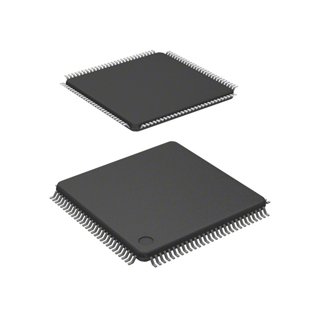
112-pin LQFP package. . . . . . . . . . . . . . . . . . . . . . . . . . . . . . . . . . . . . . . . . . . . . . . . .124
80-pin QFP package. . . . . . . . . . . . . . . . . . . . . . . . . . . . . . . . . . . . . . . . . . . . . . . . . . .125
9
For More Information On This Product,
Go to: www.freescale.com
�Freescale Semiconductor, Inc.
Freescale Semiconductor, Inc...
MC9S12DP256B Device User Guide — V02.14
10
For More Information On This Product,
Go to: www.freescale.com
�Freescale Semiconductor,
Inc.
MC9S12DP256B Device User Guide —
V02.14
Freescale Semiconductor, Inc...
List of Figures
Figure 0-1
Figure 1-1
Figure 1-2
Figure 2-1
Figure 2-2
Figure 2-3
Figure 2-4
Figure 3-1
Figure 20-1
Figure 20-2
Figure A-1
Figure A-2
Figure A-3
Figure A-4
Figure A-5
Figure A-6
Figure A-7
Figure A-8
Figure A-9
Figure B-1
Figure B-2
Order Part Number Example . . . . . . . . . . . . . . . . . . . . . . . . . . . . . . . . . . . . . . . .16
MC9S12DP256B Block Diagram . . . . . . . . . . . . . . . . . . . . . . . . . . . . . . . . . . . . .21
MC9S12DP256B Memory Map . . . . . . . . . . . . . . . . . . . . . . . . . . . . . . . . . . . . . .24
Pin Assignments in 112-pin LQFP. . . . . . . . . . . . . . . . . . . . . . . . . . . . . . . . . . . .54
Pin Assignments in 80-pin QFP for MC9S12DG256 . . . . . . . . . . . . . . . . . . . . . .55
Pin Assignments in 80-pin QFP for MC9S12DJ256 . . . . . . . . . . . . . . . . . . . . . .56
PLL Loop Filter Connections . . . . . . . . . . . . . . . . . . . . . . . . . . . . . . . . . . . . . . . .60
Clock Connections. . . . . . . . . . . . . . . . . . . . . . . . . . . . . . . . . . . . . . . . . . . . . . . .71
Recommended PCB Layout 112 LQFP. . . . . . . . . . . . . . . . . . . . . . . . . . . . . . . .85
Recommended PCB Layout for 80QFP . . . . . . . . . . . . . . . . . . . . . . . . . . . . . . .86
ATD Accuracy Definitions . . . . . . . . . . . . . . . . . . . . . . . . . . . . . . . . . . . . . . . . 100
Basic PLL functional diagram . . . . . . . . . . . . . . . . . . . . . . . . . . . . . . . . . . . . . 109
Jitter Definitions . . . . . . . . . . . . . . . . . . . . . . . . . . . . . . . . . . . . . . . . . . . . . . . . 111
Maximum bus clock jitter approximation . . . . . . . . . . . . . . . . . . . . . . . . . . . . . 111
SPI Master Timing (CPHA = 0) . . . . . . . . . . . . . . . . . . . . . . . . . . . . . . . . . . . . 115
SPI Master Timing (CPHA =1). . . . . . . . . . . . . . . . . . . . . . . . . . . . . . . . . . . . . 116
SPI Slave Timing (CPHA = 0) . . . . . . . . . . . . . . . . . . . . . . . . . . . . . . . . . . . . . 117
SPI Slave Timing (CPHA =1). . . . . . . . . . . . . . . . . . . . . . . . . . . . . . . . . . . . . . 117
General External Bus Timing. . . . . . . . . . . . . . . . . . . . . . . . . . . . . . . . . . . . . . 120
112-pin LQFP mechanical dimensions (case no. 987) . . . . . . . . . . . . . . . . . . 124
80-pin QFP Mechanical Dimensions (case no. 841B) . . . . . . . . . . . . . . . . . . . 125
11
For More Information On This Product,
Go to: www.freescale.com
�Freescale Semiconductor, Inc.
Freescale Semiconductor, Inc...
MC9S12DP256B Device User Guide — V02.14
12
For More Information On This Product,
Go to: www.freescale.com
�Freescale Semiconductor,
Inc.
MC9S12DP256B Device User Guide —
V02.14
Freescale Semiconductor, Inc...
List of Tables
Table 0-1
Table 0-2
Table 0-4
Table 0-3
Table 1-1
Table 1-2
Table 1-3
Table 1-4
Table 2-1
Table 2-2
Table 4-1
Table 4-2
Table 4-3
Table 5-1
Table 6-1
Table A-1
Table A-2
Table A-3
Table A-4
Table A-5
Table A-6
Table A-7
Table A-8
Table A-9
Table A-10
Table A-11
Table A-12
Table A-13
Table A-14
Table A-15
Table A-16
Table A-17
Table A-18
Drivative Differences MC9S12D256B . . . . . . . . . . . . . . . . . . . . . . . . . . . . . . . . . .15
Derivative Differences MC9S12D256C . . . . . . . . . . . . . . . . . . . . . . . . . . . . . . . . .15
Document References . . . . . . . . . . . . . . . . . . . . . . . . . . . . . . . . . . . . . . . . . . . . . .16
Defects fixed on Maskset 2K79X . . . . . . . . . . . . . . . . . . . . . . . . . . . . . . . . . . . . . .16
Device Memory Map . . . . . . . . . . . . . . . . . . . . . . . . . . . . . . . . . . . . . . . . . . . . . . .22
Detailed MSCAN Foreground Receive and Transmit Buffer Layout. . . . . . . . . . .41
Assigned Part ID Numbers . . . . . . . . . . . . . . . . . . . . . . . . . . . . . . . . . . . . . . . . . .51
Memory size registers . . . . . . . . . . . . . . . . . . . . . . . . . . . . . . . . . . . . . . . . . . . . . .51
Signal Properties . . . . . . . . . . . . . . . . . . . . . . . . . . . . . . . . . . . . . . . . . . . . . . . . . .56
MC9S12DP256 Power and Ground Connection Summary . . . . . . . . . . . . . . . . . .69
Mode Selection . . . . . . . . . . . . . . . . . . . . . . . . . . . . . . . . . . . . . . . . . . . . . . . . . . .73
Clock Selection Based on PE7 . . . . . . . . . . . . . . . . . . . . . . . . . . . . . . . . . . . . . . .73
Voltage Regulator VREGEN . . . . . . . . . . . . . . . . . . . . . . . . . . . . . . . . . . . . . . . . .74
Interrupt Vector Locations . . . . . . . . . . . . . . . . . . . . . . . . . . . . . . . . . . . . . . . . . . .77
Configuration of HCS12 Core . . . . . . . . . . . . . . . . . . . . . . . . . . . . . . . . . . . . . . . .81
Absolute Maximum Ratings . . . . . . . . . . . . . . . . . . . . . . . . . . . . . . . . . . . . . . . . . .89
ESD and Latch-up Test Conditions . . . . . . . . . . . . . . . . . . . . . . . . . . . . . . . . . . . .90
ESD and Latch-Up Protection Characteristics . . . . . . . . . . . . . . . . . . . . . . . . . . . .90
Operating Conditions . . . . . . . . . . . . . . . . . . . . . . . . . . . . . . . . . . . . . . . . . . . . . . .91
Thermal Package Characteristics . . . . . . . . . . . . . . . . . . . . . . . . . . . . . . . . . . . . .93
5V I/O Characteristics . . . . . . . . . . . . . . . . . . . . . . . . . . . . . . . . . . . . . . . . . . . . . .94
Supply Current Characteristics . . . . . . . . . . . . . . . . . . . . . . . . . . . . . . . . . . . . . . .96
ATD Operating Characteristics . . . . . . . . . . . . . . . . . . . . . . . . . . . . . . . . . . . . . . .97
ATD Electrical Characteristics . . . . . . . . . . . . . . . . . . . . . . . . . . . . . . . . . . . . . . . .98
ATD Conversion Performance . . . . . . . . . . . . . . . . . . . . . . . . . . . . . . . . . . . . . . .99
NVM Timing Characteristics . . . . . . . . . . . . . . . . . . . . . . . . . . . . . . . . . . . . . . . .102
NVM Reliability Characteristics. . . . . . . . . . . . . . . . . . . . . . . . . . . . . . . . . . . . . .103
Voltage Regulator Recommended Load Capacitances . . . . . . . . . . . . . . . . . . .105
Startup Characteristics. . . . . . . . . . . . . . . . . . . . . . . . . . . . . . . . . . . . . . . . . . . . .107
Oscillator Characteristics . . . . . . . . . . . . . . . . . . . . . . . . . . . . . . . . . . . . . . . . . . .108
PLL Characteristics. . . . . . . . . . . . . . . . . . . . . . . . . . . . . . . . . . . . . . . . . . . . . . .112
MSCAN Wake-up Pulse Characteristics. . . . . . . . . . . . . . . . . . . . . . . . . . . . . . .113
SPI Master Mode Timing Characteristics. . . . . . . . . . . . . . . . . . . . . . . . . . . . . . .116
13
For More Information On This Product,
Go to: www.freescale.com
�Freescale Semiconductor, Inc.
MC9S12DP256B Device User Guide — V02.14
Freescale Semiconductor, Inc...
Table A-19 SPI Slave Mode Timing Characteristics . . . . . . . . . . . . . . . . . . . . . . . . . . . . . . .118
Table A-20 Expanded Bus Timing Characteristics . . . . . . . . . . . . . . . . . . . . . . . . . . . . . . . .121
14
For More Information On This Product,
Go to: www.freescale.com
�Freescale Semiconductor,
Inc.
MC9S12DP256B Device User Guide —
V02.14
Preface
The Device User Guide provides information about the MC9S12DP256B device made up of standard
HCS12 blocks and the HCS12 processor core.
Table 0-1 and Table 0-2 show the availability of peripheral modules on the various derivatives. For
details about the compatibility within the MC9S12D-Family refer also to engineering bulletin EB386.
Freescale Semiconductor, Inc...
Table 0-1 Drivative Differences MC9S12D256B
Generic
device
MC9S12DP256B
MC9S12DT256B
MC9S12DJ256B
MC9S12DG256B
MC9S12A256B
# of CANs
5
3
2
2
0
CAN0
✓
✓
✓
✓
✓
✓
✓
✓
✓
✓
✓
✓
J1850/BDLC
✓
✓
Package
112 LQFP
112 LQFP
112 LQFP/80 QFP
112 LQFP/80 QFP
112 LQFP/80 QFP
CAN1
CAN2
CAN3
CAN4
Mask set
0/1K79X
0/1K79X
0/1K79X
0/1K79X
0/1K79X
Temp Options
M, V, C
M, V, C
M, V, C
M, V, C
C
package
Code
PV
PV
PV/FU
PV
PV/FU
Notes
An errata exists
An errata exists
An errata exists
An errata exists
An errata exists
conntact Sales office conntact Sales office conntact Sales office conntact Sales office conntact Sales office
Table 0-2 Derivative Differences MC9S12D256C
Generic
device
MC9S12DP256C
MC9S12DT256C
MC9S12DJ256C
MC9S12DG256C
# of CANs
5
3
2
2
CAN0
✓
✓
✓
✓
✓
✓
✓
✓
J1850/BDLC
✓
✓
✓
✓
✓
✓
CAN1
CAN2
CAN3
CAN4
Package
112 LQFP
112 LQFP
112 LQFP/80 QFP
112 LQFP/80 QFP
Mask set
2K79X
2K79X
2K79X
2K79X
Temp Options
M, V, C
M, V, C
M, V, C
M, V, C
package
Code
PV
PV
PV/FU
PV
Notes
An errata exists
An errata exists
An errata exists
An errata exists
conntact Sales office conntact Sales office conntact Sales office conntact Sales office
15
For More Information On This Product,
Go to: www.freescale.com
�Freescale Semiconductor, Inc.
MC9S12DP256B Device User Guide — V02.14
Table 0-3 shows the defects fixed on maskset 2K79X (MC9S12DP256C)
Table 0-3 Defects fixed on Maskset 2K79X
Defect
MUCts00510
MUCts00604
MUCts00603
Headline
SCI interrupt asserts only if odd number of interrupts active
Security in Normal Single Chip mode
Security in Normal Single Chip mode
Freescale Semiconductor, Inc...
This document is part of the customer documentation. A complete set of device manuals also includes the
HCS12 Core User Guide and all the individual Block User Guides of the implemented modules. In a effort
to reduce redundancy all module specific information is located only in the respective Block User Guide.
If applicable, special implementation details of the module are given in the block description sections of
this document.
MC9S12 DP256C C FU
Package Option
Temperature Option
Device Title
Controller Family
Temperature Options
C = -40˚C to 85˚C
V = -40˚C to 105˚C
M = -40˚C to 125˚C
Package Options
FU = 80QFP
PV = 112 LQFP
Figure 0-1 Order Part Number Example
See Table 0-4 for names and versions of the referenced documents throughout the Device User Guide.
Table 0-4 Document References
User Guide
HCS12 V1.5 Core User Guide
Version
Document Order Number
1.2
HCS12COREUG
CRG Block User Guide
V02
S12CRGV2/D
ECT_16B8C Block User Guide
V01
S12ECT16B8CV1/D
ATD_10B8C Block User Guide
V02
S12ATD10B8CV2/D
IIC Block User Guide
V02
S12IICV2/D
SCI Block User Guide
V02
S12SCIV2/D
SPI Block User Guide
V02
S12SPIV2/D
PWM_8B8C Block User Guide
V01
S12PWM8B8CV1/D
FTS256K Block User Guide
V02
S12FTS256KV2/D
EETS4K Block User Guide
V02
S12EETS4KV2/D
BDLC Block User Guide
V01
S12BDLCV1/D
MSCAN Block User Guide
V02
S12MSCANV2/D
VREG Block User Guide
V01
S12VREGV1/D
PIM_9DP256 Block User Guide
V02
S12PIM9DP256V2/D
16
For More Information On This Product,
Go to: www.freescale.com
�Freescale Semiconductor,
Inc.
MC9S12DP256B Device User Guide —
V02.14
Section 1 Introduction
Freescale Semiconductor, Inc...
1.1 Overview
The MC9S12DP256 microcontroller unit (MCU) is a 16-bit device composed of standard on-chip
peripherals including a 16-bit central processing unit (HCS12 CPU), 256K bytes of Flash EEPROM, 12K
bytes of RAM, 4K bytes of EEPROM, two asynchronous serial communications interfaces (SCI), three
serial peripheral interfaces (SPI), an 8-channel IC/OC enhanced capture timer, two 8-channel, 10-bit
analog-to-digital converters (ADC), an 8-channel pulse-width modulator (PWM), a digital Byte Data Link
Controller (BDLC), 29 discrete digital I/O channels (Port A, Port B, Port K and Port E), 20 discrete digital
I/O lines with interrupt and wakeup capability, five CAN 2.0 A, B software compatible modules
(MSCAN12), and an Inter-IC Bus. The MC9S12DP256 has full 16-bit data paths throughout. However,
the external bus can operate in an 8-bit narrow mode so single 8-bit wide memory can be interfaced for
lower cost systems. The inclusion of a PLL circuit allows power consumption and performance to be
adjusted to suit operational requirements.
1.2 Features
•
HCS12 Core
–
16-bit HCS12 CPU
i. Upward compatible with M68HC11 instruction set
ii. Interrupt stacking and programmer’s model identical to M68HC11
iii. Instruction queue
iv. Enhanced indexed addressing
–
MEBI (Multiplexed External Bus Interface)
–
MMC (Module Mapping Control)
–
INT (Interrupt control)
–
BKP (Breakpoints)
–
BDM (Background Debug Mode)
•
CRG (low current oscillator, PLL, reset, clocks, COP watchdog, real time interrupt, clock monitor)
•
8-bit and 4-bit ports with interrupt functionality
•
–
Digital filtering
–
Programmable rising or falling edge trigger
Memory
–
256K Flash EEPROM
–
4K byte EEPROM
–
12K byte RAM
17
For More Information On This Product,
Go to: www.freescale.com
�Freescale Semiconductor, Inc.
MC9S12DP256B Device User Guide — V02.14
•
Freescale Semiconductor, Inc...
•
•
•
•
•
Two 8-channel Analog-to-Digital Converters
–
10-bit resolution
–
External conversion trigger capability
Five 1M bit per second, CAN 2.0 A, B software compatible modules
–
Five receive and three transmit buffers
–
Flexible identifier filter programmable as 2 x 32 bit, 4 x 16 bit or 8 x 8 bit
–
Four separate interrupt channels for Rx, Tx, error and wake-up
–
Low-pass filter wake-up function
–
Loop-back for self test operation
Enhanced Capture Timer
–
16-bit main counter with 7-bit prescaler
–
8 programmable input capture or output compare channels
–
Two 8-bit or one 16-bit pulse accumulators
8 PWM channels
–
Programmable period and duty cycle
–
8-bit 8-channel or 16-bit 4-channel
–
Separate control for each pulse width and duty cycle
–
Center-aligned or left-aligned outputs
–
Programmable clock select logic with a wide range of frequencies
–
Fast emergency shutdown input
–
Usable as interrupt inputs
Serial interfaces
–
Two asynchronous Serial Communications Interfaces (SCI)
–
Three Synchronous Serial Peripheral Interface (SPI)
Byte Data Link Controller (BDLC)
–
•
•
SAE J1850 Class B Data Communications Network Interface Compatible and ISO Compatible
for Low-Speed (=100nF
C5
VDDPLL filter cap
ceramic X7R
100nF
C6
VDDX filter cap
X7R/tantalum
>=100nF
C7
OSC load cap
C8
OSC load cap
C9
PLL loop filter cap
C10
PLL loop filter cap
C11
DC cutoff cap
R1
PLL loop filter res
Q1
Quartz
See PLL specification chapter
The PCB must be carefully laid out to ensure proper operation of the voltage regulator as well as
of the MCU itself. The following rules must be observed:
83
For More Information On This Product,
Go to: www.freescale.com
�Freescale Semiconductor, Inc.
Freescale Semiconductor, Inc...
MC9S12DP256B Device User Guide — V02.14
•
Every supply pair must be decoupled by a ceramic capacitor connected as near as
possible to the corresponding pins(C1 - C6).
•
Central point of the ground star should be the VSSR pin.
•
Use low ohmic low inductance connections between VSS1, VSS2 and VSSR.
•
VSSPLL must be directly connected to VSSR.
•
Keep traces of VSSPLL, EXTAL and XTAL as short as possible and occupied board area
for C7, C8, C11 and Q1 as small as possible.
•
Do not place other signals or supplies underneath area occupied by C7, C8, C10 and Q1
and the connection area to the MCU.
•
Central power input should be fed in at the VDDA/VSSA pins.
84
For More Information On This Product,
Go to: www.freescale.com
�Freescale Semiconductor,
Inc.
MC9S12DP256B Device User Guide —
V02.14
Figure 20-1 Recommended PCB Layout 112 LQFP
VREGEN
C6
VDDX
VSSX
VSSA
C3
VDD1
C1
VSS1
VSS2
C2
VDD2
VSSR
C4
C7
C8
C10
R1
C11
C5
VDDR
C9
Freescale Semiconductor, Inc...
VDDA
Q1
VSSPLL
VDDPLL
85
For More Information On This Product,
Go to: www.freescale.com
�Freescale Semiconductor, Inc.
MC9S12DP256B Device User Guide — V02.14
Figure 20-2 Recommended PCB Layout for 80QFP
VREGEN
C6
VDDX
VSSX
VSSA
C3
VDDA
VDD1
Freescale Semiconductor, Inc...
VSS2
C1
C2
VSS1
VDD2
VSSR
C4
C5
VDDR
C7
C8
C11
Q1
C10
C9
R1
VSSPLL
VDDPLL
86
For More Information On This Product,
Go to: www.freescale.com
�Freescale Semiconductor,
Inc.
MC9S12DP256B Device User Guide —
V02.14
Appendix A Electrical Characteristics
A.1 General
NOTE:
The electrical characteristics given in this section are preliminary and should be
used as a guide only. Values cannot be guaranteed by Motorola and are subject to
change without notice.
Freescale Semiconductor, Inc...
This supplement contains the most accurate electrical information for the MC9S12DP256B
microcontroller available at the time of publication. The information should be considered
PRELIMINARY and is subject to change.
This introduction is intended to give an overview on several common topics like power supply, current
injection etc.
A.1.1 Parameter Classification
The electrical parameters shown in this supplement are guaranteed by various methods. To give the
customer a better understanding the following classification is used and the parameters are tagged
accordingly in the tables where appropriate.
NOTE:
This classification is shown in the column labeled “C” in the parameter tables
where appropriate.
P:
Those parameters are guaranteed during production testing on each individual device.
C:
Those parameters are achieved by the design characterization by measuring a statistically relevant
sample size across process variations.
T:
Those parameters are achieved by design characterization on a small sample size from typical devices
under typical conditions unless otherwise noted. All values shown in the typical column are within
this category.
D:
Those parameters are derived mainly from simulations.
A.1.2 Power Supply
The MC9S12DP256B utilizes several pins to supply power to the I/O ports, A/D converter, oscillator and
PLL as well as the digital core.
The VDDA, VSSA pair supplies the A/D converter and the resistor ladder of the internal voltage regulator.
87
For More Information On This Product,
Go to: www.freescale.com
�Freescale Semiconductor, Inc.
MC9S12DP256B Device User Guide — V02.14
The VDDX, VSSX, VDDR and VSSR pairs supply the I/O pins, VDDR supplies also the internal voltage
regulator.
VDD1, VSS1, VDD2 and VSS2 are the supply pins for the digital logic, VDDPLL, VSSPLL supply the
oscillator and the PLL.
VSS1 and VSS2 are internally connected by metal.
VDDA, VDDX, VDDR as well as VSSA, VSSX, VSSR are connected by anti-parallel diodes for ESD
protection.
Freescale Semiconductor, Inc...
NOTE:
In the following context VDD5 is used for either VDDA, VDDR and VDDX; VSS5
is used for either VSSA, VSSR and VSSX unless otherwise noted.
IDD5 denotes the sum of the currents flowing into the VDDA, VDDX and VDDR
pins.
VDD is used for VDD1, VDD2 and VDDPLL, VSS is used for VSS1, VSS2 and
VSSPLL.
IDD is used for the sum of the currents flowing into VDD1 and VDD2.
A.1.3 Pins
There are four groups of functional pins.
A.1.3.1 5V I/O pins
Those I/O pins have a nominal level of 5V. This class of pins is comprised of all port I/O pins, the analog
inputs, BKGD and the RESET pins.The internal structure of all those pins is identical, however some of
the functionality may be disabled. E.g. for the analog inputs the output drivers, pull-up and pull-down
resistors are disabled permanently.
A.1.3.2 Analog Reference
This group is made up by the VRH and VRL pins.
A.1.3.3 Oscillator
The pins XFC, EXTAL, XTAL dedicated to the oscillator have a nominal 2.5V level. They are supplied
by VDDPLL.
A.1.3.4 TEST
This pin is used for production testing only.
A.1.3.5 VREGEN
This pin is used to enable the on chip voltage regulator.
88
For More Information On This Product,
Go to: www.freescale.com
�Freescale Semiconductor,
Inc.
MC9S12DP256B Device User Guide —
V02.14
A.1.4 Current Injection
Power supply must maintain regulation within operating VDD5 or VDD range during instantaneous and
operating maximum current conditions. If positive injection current (Vin > VDD5) is greater than IDD5, the
injection current may flow out of VDD5 and could result in external power supply going out of regulation.
Ensure external VDD5 load will shunt current greater than maximum injection current. This will be the
greatest risk when the MCU is not consuming power; e.g. if no system clock is present, or if clock rate is
very low which would reduce overall power consumption.
Freescale Semiconductor, Inc...
A.1.5 Absolute Maximum Ratings
Absolute maximum ratings are stress ratings only. A functional operation under or outside those maxima
is not guaranteed. Stress beyond those limits may affect the reliability or cause permanent damage of the
device.
This device contains circuitry protecting against damage due to high static voltage or electrical fields;
however, it is advised that normal precautions be taken to avoid application of any voltages higher than
maximum-rated voltages to this high-impedance circuit. Reliability of operation is enhanced if unused
inputs are tied to an appropriate logic voltage level (e.g., either VSS5 or VDD5).
Table A-1 Absolute Maximum Ratings1
Num
Rating
Symbol
Min
Max
Unit
1
I/O, Regulator and Analog Supply Voltage
VDD5
-0.3
6.0
V
2
Digital Logic Supply Voltage 2
VDD
-0.3
3.0
V
3
PLL Supply Voltage 2
VDDPLL
-0.3
3.0
V
4
Voltage difference VDDX to VDDR and VDDA
∆VDDX
-0.3
0.3
V
5
Voltage difference VSSX to VSSR and VSSA
∆VSSX
-0.3
0.3
V
6
Digital I/O Input Voltage
VIN
-0.3
6.0
V
7
Analog Reference
VRH, VRL
-0.3
6.0
V
8
XFC, EXTAL, XTAL inputs
VILV
-0.3
3.0
V
9
TEST input
VTEST
-0.3
10.0
V
10
Instantaneous Maximum Current
Single pin limit for all digital I/O pins 3
ID
-25
+25
mA
11
Instantaneous Maximum Current
Single pin limit for XFC, EXTAL, XTAL4
IDL
-25
+25
mA
12
Instantaneous Maximum Current
Single pin limit for TEST 5
IDT
-0.25
0
mA
13
Storage Temperature Range
T
– 65
155
°C
stg
NOTES:
1. Beyond absolute maximum ratings device might be damaged.
89
For More Information On This Product,
Go to: www.freescale.com
�Freescale Semiconductor, Inc.
MC9S12DP256B Device User Guide — V02.14
2. The device contains an internal voltage regulator to generate the logic and PLL supply out of the I/O supply.
The absolute maximum ratings apply when the device is powered from an external source.
3. All digital I/O pins are internally clamped to VSSX and VDDX, VSSR and VDDR or VSSA and VDDA.
4. Those pins are internally clamped to VSSPLL and VDDPLL.
5. This pin is clamped low to VSSPLL, but not clamped high. This pin must be tied low in applications.
A.1.6 ESD Protection and Latch-up Immunity
Freescale Semiconductor, Inc...
All ESD testing is in conformity with CDF-AEC-Q100 Stress test qualification for Automotive Grade
Integrated Circuits. During the device qualification ESD stresses were performed for the Human Body
Model (HBM), the Machine Model (MM) and the Charge Device Model.
A device will be defined as a failure if after exposure to ESD pulses the device no longer meets the device
specification. Complete DC parametric and functional testing is performed per the applicable device
specification at room temperature followed by hot temperature, unless specified otherwise in the device
specification.
Table A-2 ESD and Latch-up Test Conditions
Model
Human Body
Machine
Description
Symbol
Value
Unit
Series Resistance
R1
1500
Ohm
Storage Capacitance
C
100
pF
Number of Pulse per pin
positive
negative
-
3
3
Series Resistance
R1
0
Ohm
Storage Capacitance
C
200
pF
Number of Pulse per pin
positive
negative
-
3
3
Minimum input voltage limit
-2.5
V
Maximum input voltage limit
7.5
V
Latch-up
Table A-3 ESD and Latch-Up Protection Characteristics
Num C
Rating
Symbol
Min
Max
Unit
1
C Human Body Model (HBM)
VHBM
2000
-
V
2
C Machine Model (MM)
VMM
200
-
V
3
C Charge Device Model (CDM)
VCDM
500
-
V
4
Latch-up Current at TA = 125°C
C positive
negative
ILAT
+100
-100
-
mA
5
Latch-up Current at TA = 27°C
C positive
negative
ILAT
+200
-200
-
mA
90
For More Information On This Product,
Go to: www.freescale.com
�Freescale Semiconductor,
Inc.
MC9S12DP256B Device User Guide —
V02.14
A.1.7 Operating Conditions
This chapter describes the operating conditions of the device. Unless otherwise noted those conditions
apply to all the following data.
NOTE:
Please refer to the temperature rating of the device (C, V, M) with regards to the
ambient temperature TA and the junction temperature TJ. For power dissipation
calculations refer to Section A.1.8 Power Dissipation and Thermal
Characteristics.
Table A-4 Operating Conditions
Freescale Semiconductor, Inc...
Rating
Symbol
Min
Typ
Max
Unit
I/O, Regulator and Analog Supply Voltage
VDD5
4.5
5
5.25
V
Digital Logic Supply Voltage 1
VDD
2.35
2.5
2.75
V
PLL Supply Voltage 2
VDDPLL
2.35
2.5
2.75
V
Voltage Difference VDDX to VDDR and VDDA
∆VDDX
-0.1
0
0.1
V
Voltage Difference VSSX to VSSR and VSSA
∆VSSX
-0.1
0
0.1
V
Oscillator
fosc
0.5
-
16
MHz
Bus Frequency
fbus
0.5
-
25
MHz
TJ
-40
-
100
°C
T
A
-40
27
85
°C
Operating Junction Temperature Range
TJ
-40
-
120
°C
Operating Ambient Temperature Range 2
TA
-40
27
105
°C
Operating Junction Temperature Range
TJ
-40
-
140
°C
Operating Ambient Temperature Range 2
TA
-40
27
125
°C
MC9S12DP256BC
Operating Junction Temperature Range
Operating Ambient Temperature Range 2
MC9S12DP256BV
MC9S12DP256BM
NOTES:
1. The device contains an internal voltage regulator to generate the logic and PLL supply out of the I/O supply. The
absolute maximum ratings apply when this regulator is disabled and the device is powered from an external
source.
2. Please refer to Section A.1.8 Power Dissipation and Thermal Characteristics for more details about the relation between ambient temperature TA and device junction temperature TJ.
A.1.8 Power Dissipation and Thermal Characteristics
Power dissipation and thermal characteristics are closely related. The user must assure that the maximum
operating junction temperature is not exceeded. The average chip-junction temperature (TJ) in °C can be
obtained from:
91
For More Information On This Product,
Go to: www.freescale.com
�Freescale Semiconductor, Inc.
MC9S12DP256B Device User Guide — V02.14
T J = T A + ( P D • Θ JA )
T J = Junction Temperature, [°C ]
T A = Ambient Temperature, [°C ]
P D = Total Chip Power Dissipation, [W]
Θ JA = Package Thermal Resistance, [°C/W]
The total power dissipation can be calculated from:
Freescale Semiconductor, Inc...
P D = P INT + P IO
P INT = Chip Internal Power Dissipation, [W]
Two cases with internal voltage regulator enabled and disabled must be considered:
1. Internal Voltage Regulator disabled
P INT = I DD ⋅ V DD + I DDPLL ⋅ V DDPLL + I DDA ⋅ V DDA
2
P IO =
R DSON ⋅ I IO
i
i
∑
PIO is the sum of all output currents on I/O ports associated with VDDX and VDDR.
For RDSON is valid:
V OL
R DSON = ------------ ;for outputs driven low
I OL
respectively
V DD5 – V OH
R DSON = ------------------------------------ ;for outputs driven high
I OH
2. Internal voltage regulator enabled
P INT = I DDR ⋅ V DDR + I DDA ⋅ V DDA
IDDR is the current shown in Table A-7 and not the overall current flowing into VDDR, which
additionally contains the current flowing into the external loads with output high.
2
P IO =
R DSON ⋅ I IO
i
i
∑
PIO is the sum of all output currents on I/O ports associated with VDDX and VDDR.
92
For More Information On This Product,
Go to: www.freescale.com
�Freescale Semiconductor,
Inc.
MC9S12DP256B Device User Guide —
V02.14
Table A-5 Thermal Package Characteristics1
Freescale Semiconductor, Inc...
Num C
Rating
Symbol
Min
Typ
Max
Unit
1
T Thermal Resistance LQFP112, single sided PCB2
θJA
-
-
54
o
2
T
Thermal Resistance LQFP112, double sided PCB
with 2 internal planes3
θJA
-
-
41
o
3
T Thermal Resistance LQFP 80, single sided PCB
θJA
-
-
51
oC/W
4
T
θJA
-
-
41
o
Thermal Resistance LQFP 80, double sided PCB
with 2 internal planes
C/W
C/W
C/W
NOTES:
1. The values for thermal resistance are achieved by package simulations
2. PC Board according to EIA/JEDEC Standard 51-2
3. PC Board according to EIA/JEDEC Standard 51-7
A.1.9 I/O Characteristics
This section describes the characteristics of all 5V I/O pins. All parameters are not always applicable, e.g.
not all pins feature pull up/down resistances.
93
For More Information On This Product,
Go to: www.freescale.com
�Freescale Semiconductor, Inc.
MC9S12DP256B Device User Guide — V02.14
Table A-6 5V I/O Characteristics
Conditions are shown in Table A-4 unless otherwise noted
Num C
1
Freescale Semiconductor, Inc...
2
Rating
Symbol
Min
Typ
Max
Unit
0.65*VDD5
-
-
V
P Input High Voltage
V
T Input High Voltage
VIH
-
-
VDD5 + 0.3
V
P Input Low Voltage
VIL
-
-
0.35*VDD5
V
T Input Low Voltage
VIL
VSS5 - 0.3
-
-
V
IH
VHYS
3
C Input Hysteresis
4
Input Leakage Current (pins in high impedance input
P mode)1
Vin = VDD5 or VSS5
5
250
mV
in
–2.5
-
2.5
µA
Output High Voltage (pins in output mode)
P Partial Drive IOH = –2mA
Full Drive IOH = –10mA
VOH
VDD5 – 0.8
-
-
V
6
Output Low Voltage (pins in output mode)
P Partial Drive IOL = +2mA
Full Drive IOL = +10mA
V
OL
-
-
0.8
V
7
Internal Pull Up Device Current,
P tested at V Max.
IPUL
-
-
-130
µA
Internal Pull Up Device Current,
P tested at V Min.
IPUH
-10
-
-
µA
Internal Pull Down Device Current,
P tested at V Min.
IPDH
-
-
130
µA
Internal Pull Down Device Current,
P tested at V Max.
IPDL
10
-
-
µA
11
D Input Capacitance
Cin
6
-
pF
12
Injection current2
T Single Pin limit
Total Device Limit. Sum of all injected currents
IICS
IICP
-
2.5
25
mA
13
P Port H, J, P Interrupt Input Pulse filtered3
tPULSE
3
µs
14
P Port H, J, P Interrupt Input Pulse passed3
tPULSE
IL
8
IH
9
IH
10
IL
I
-2.5
-25
10
µs
NOTES:
1. Maximum leakage current occurs at maximum operating temperature. Current decreases by approximately one-half for
each 8 C to 12 C in the temperature range from 50 C to 125 C.
2. Refer to Section A.1.4 Current Injection, for more details
3. Parameter only applies in STOP or Pseudo STOP mode.
94
For More Information On This Product,
Go to: www.freescale.com
�Freescale Semiconductor,
Inc.
MC9S12DP256B Device User Guide —
V02.14
A.1.10 Supply Currents
This section describes the current consumption characteristics of the device as well as the conditions for
the measurements.
A.1.10.1 Measurement Conditions
All measurements are without output loads. Unless otherwise noted the currents are measured in single
chip mode, internal voltage regulator enabled and at 25MHz bus frequency using a 4MHz oscillator in
Colpitts mode. Production testing is performed using a square wave signal at the EXTAL input.
Freescale Semiconductor, Inc...
A.1.10.2 Additional Remarks
In expanded modes the currents flowing in the system are highly dependent on the load at the address, data
and control signals as well as on the duty cycle of those signals. No generally applicable numbers can be
95
For More Information On This Product,
Go to: www.freescale.com
�Freescale Semiconductor, Inc.
MC9S12DP256B Device User Guide — V02.14
given. A very good estimate is to take the single chip currents and add the currents due to the external
loads.
Table A-7 Supply Current Characteristics
Conditions are shown in Table A-4 unless otherwise noted
Num C
Rating
Symbol
Run supply currents
Single Chip, Internal regulator enabled
IDD5
65
IDDW
40
5
1
P
2
P
P
All modules enabled, PLL on
only RTI enabled 1
C
P
C
C
P
C
P
C
P
Pseudo Stop Current (RTI and COP disabled) 1, 2
-40°C
27°C
70°C
85°C
"C" Temp Option 100°C
105°C
"V" Temp Option 120°C
125°C
"M" Temp Option 140°C
C
C
C
C
C
C
C
Pseudo Stop Current (RTI and COP enabled) 1, 2
-40°C
27°C
70°C
85°C
105°C
125°C
140°C
Min
Typ
Max
Unit
mA
Freescale Semiconductor, Inc...
Wait Supply current
3
4
IDDPS
IDDPS
370
400
450
550
600
650
800
850
1200
mA
500
1600
µA
2100
5000
570
600
650
750
850
1200
1500
µA
Stop Current 2
5
C
P
C
C
P
C
P
C
P
-40°C
27°C
70°C
85°C
"C" Temp Option 100°C
105°C
"V" Temp Option 120°C
125°C
"M" Temp Option 140°C
IDDS
NOTES:
1. PLL off
2. At those low power dissipation levels TJ = TA can be assumed
96
For More Information On This Product,
Go to: www.freescale.com
12
25
100
130
160
200
350
400
600
100
1200
1700
5000
µA
�Freescale Semiconductor,
Inc.
MC9S12DP256B Device User Guide —
V02.14
A.2 ATD Characteristics
This section describes the characteristics of the analog to digital converter.
A.2.1 ATD Operating Characteristics
The Table A-8 shows conditions under which the ATD operates.
The following constraints exist to obtain full-scale, full range results:
VSSA ≤ VRL ≤ VIN ≤ VRH ≤ VDDA. This constraint exists since the sample buffer amplifier can not drive
beyond the power supply levels that it ties to. If the input level goes outside of this range it will effectively
be clipped.
Freescale Semiconductor, Inc...
Table A-8 ATD Operating Characteristics
Conditions are shown in Table A-4 unless otherwise noted
Num C
Rating
Symbol
Min
VRL
VRH
VSSA
VDDA/2
Typ
Max
Unit
VDDA/2
VDDA
V
V
5.25
V
Reference Potential
1
D
Low
High
2
C Differential Reference Voltage1
VRH-VRL
4.50
3
D ATD Clock Frequency
fATDCLK
0.5
2.0
MHz
4
D
14
7
28
14
Cycles
µs
5
D
12
6
26
13
Cycles
µs
6
D Recovery Time (VDDA=5.0 Volts)
tREC
20
µs
7
P
Reference Supply current 2 ATD blocks on
IREF
0.750
mA
8
P
Reference Supply current 1 ATD block on
IREF
0.375
mA
5.00
ATD 10-Bit Conversion Period
Clock Cycles2 NCONV10
Conv, Time at 2.0MHz ATD Clock fATDCLK TCONV10
ATD 8-Bit Conversion Period
Clock Cycles2
Conv, Time at 2.0MHz ATD Clock fATDCLK
NCONV8
TCONV8
NOTES:
1. Full accuracy is not guaranteed when differential voltage is less than 4.50V
2. The minimum time assumes a final sample period of 2 ATD clocks cycles while the maximum time assumes a final sample
period of 16 ATD clocks.
A.2.2 Factors influencing accuracy
Three factors - source resistance, source capacitance and current injection - have an influence on the
accuracy of the ATD.
A.2.2.1 Source Resistance:
Due to the input pin leakage current as specified in Table A-6 in conjunction with the source resistance
there will be a voltage drop from the signal source to the ATD input. The maximum source resistance RS
97
For More Information On This Product,
Go to: www.freescale.com
�Freescale Semiconductor, Inc.
MC9S12DP256B Device User Guide — V02.14
specifies results in an error of less than 1/2 LSB (2.5mV) at the maximum leakage current. If device or
operating conditions are less than worst case or leakage-induced error is acceptable, larger values of source
resistance is allowed.
A.2.2.2 Source Capacitance
When sampling an additional internal capacitor is switched to the input. This can cause a voltage drop due
to charge sharing with the external and the pin capacitance. For a maximum sampling error of the input
voltage ≤ 1LSB, then the external filter capacitor, Cf ≥ 1024 * (CINS- CINN).
A.2.2.3 Current Injection
Freescale Semiconductor, Inc...
There are two cases to consider.
1. A current is injected into the channel being converted. The channel being stressed has conversion
values of $3FF ($FF in 8-bit mode) for analog inputs greater than VRH and $000 for values less than
VRL unless the current is higher than specified as disruptive condition.
2. Current is injected into pins in the neighborhood of the channel being converted. A portion of this
current is picked up by the channel (coupling ratio K), This additional current impacts the accuracy
of the conversion depending on the source resistance.
The additional input voltage error on the converted channel can be calculated as VERR = K * RS *
IINJ, with IINJ being the sum of the currents injected into the two pins adjacent to the converted
channel.
Table A-9 ATD Electrical Characteristics
Conditions are shown in Table A-4 unless otherwise noted
Num C
Rating
Symbol
Min
Typ
Max
Unit
RS
-
-
1
KΩ
10
22
pF
2.5
mA
1
C Max input Source Resistance
2
Total Input Capacitance
T Non Sampling
Sampling
3
C Disruptive Analog Input Current
INA
4
C Coupling Ratio positive current injection
Kp
10-4
A/A
5
C Coupling Ratio negative current injection
Kn
10-2
A/A
CINN
CINS
-2.5
98
For More Information On This Product,
Go to: www.freescale.com
�Freescale Semiconductor,
Inc.
MC9S12DP256B Device User Guide —
V02.14
A.2.3 ATD accuracy
Table A-10 specifies the ATD conversion performance excluding any errors due to current injection,
input capacitance and source resistance.
Table A-10 ATD Conversion Performance
Conditions are shown in Table A-4 unless otherwise noted
VREF = VRH - VRL = 5.12V. Resulting to one 8 bit count = 20mV and one 10 bit count = 5mV
fATDCLK = 2.0MHz
Freescale Semiconductor, Inc...
Num C
Rating
Symbol
Min
1
P 10-Bit Resolution
LSB
2
P 10-Bit Differential Nonlinearity
DNL
–1
3
P 10-Bit Integral Nonlinearity
INL
–2.5
4
P 10-Bit Absolute Error1
AE
-3
5
P 8-Bit Resolution
LSB
6
P 8-Bit Differential Nonlinearity
DNL
–0.5
7
P 8-Bit Integral Nonlinearity
INL
–1.0
AE
-1.5
8
P 8-Bit Absolute
Error1
Typ
Max
5
Unit
mV
1
Counts
±1.5
2.5
Counts
±2.0
3
Counts
20
mV
0.5
Counts
±0.5
1.0
Counts
±1.0
1.5
Counts
NOTES:
1. These values include the quantization error which is inherently 1/2 count for any A/D converter.
For the following definitions see also Figure A-1.
Differential Non-Linearity (DNL) is defined as the difference between two adjacent switching steps.
Vi – Vi – 1
DNL ( i ) = ------------------------ – 1
1LSB
The Integral Non-Linearity (INL) is defined as the sum of all DNLs:
n
INL ( n ) =
∑
i=1
Vn – V0
DNL ( i ) = -------------------- – n
1LSB
99
For More Information On This Product,
Go to: www.freescale.com
�Freescale Semiconductor, Inc.
MC9S12DP256B Device User Guide — V02.14
DNL
10-Bit Absolute Error Boundary
LSB
Vi-1
Vi
$3FF
8-Bit Absolute Error Boundary
$3FE
$3FD
$FF
$3FB
$3FA
$3F9
$3F8
$FE
$3F7
$3F6
$3F4
8-Bit Resolution
$3F5
10-Bit Resolution
Freescale Semiconductor, Inc...
$3FC
$FD
$3F3
9
Ideal Transfer Curve
8
2
7
10-Bit Transfer Curve
6
5
4
1
3
8-Bit Transfer Curve
2
1
0
5
10
15
20
25
30
35
40
50
5055 5060 5065 5070 5075 5080 5085 5090 5095 5100 5105 5110 5115 5120
Vin
mV
Figure A-1 ATD Accuracy Definitions
NOTE:
Figure A-1 shows only definitions, for specification values refer to Table A-10.
100
For More Information On This Product,
Go to: www.freescale.com
�Freescale Semiconductor,
Inc.
MC9S12DP256B Device User Guide —
V02.14
A.3 NVM, Flash and EEPROM
NOTE:
Unless otherwise noted the abbreviation NVM (Non Volatile Memory) is used for
both Flash and EEPROM.
A.3.1 NVM timing
Freescale Semiconductor, Inc...
The time base for all NVM program or erase operations is derived from the oscillator. A minimum
oscillator frequency fNVMOSC is required for performing program or erase operations. The NVM modules
do not have any means to monitor the frequency and will not prevent program or erase operation at
frequencies above or below the specified minimum. Attempting to program or erase the NVM modules at
a lower frequency a full program or erase transition is not assured.
The Flash and EEPROM program and erase operations are timed using a clock derived from the oscillator
using the FCLKDIV and ECLKDIV registers respectively. The frequency of this clock must be set within
the limits specified as fNVMOP.
The minimum program and erase times shown in Table A-11 are calculated for maximum fNVMOP and
maximum fbus. The maximum times are calculated for minimum fNVMOP and a fbus of 2MHz.
A.3.1.1 Single Word Programming
The programming time for single word programming is dependant on the bus frequency as a well as on
the frequency fNVMOP and can be calculated according to the following formula.
1
1
t swpgm = 9 ⋅ --------------------- + 25 ⋅ ---------f NVMOP
f bus
A.3.1.2 Burst Programming
This applies only to the Flash where up to 32 words in a row can be programmed consecutively using burst
programming by keeping the command pipeline filled. The time to program a consecutive word can be
calculated as:
1
1
t bwpgm = 4 ⋅ --------------------- + 9 ⋅ ---------f NVMOP
f bus
The time to program a whole row is:
t brpgm = t swpgm + 31 ⋅ t bwpgm
Burst programming is more than 2 times faster than single word programming.
101
For More Information On This Product,
Go to: www.freescale.com
�Freescale Semiconductor, Inc.
MC9S12DP256B Device User Guide — V02.14
A.3.1.3 Sector Erase
Erasing a 512 byte Flash sector or a 4 byte EEPROM sector takes:
1
t era ≈ 4000 ⋅ --------------------f NVMOP
The setup time can be ignored for this operation.
A.3.1.4 Mass Erase
Erasing a NVM block takes:
Freescale Semiconductor, Inc...
1
t mass ≈ 20000 ⋅ --------------------f NVMOP
The setup time can be ignored for this operation.
A.3.1.5 Blank Check
The time it takes to perform a blank check on the Flash or EEPROM is dependant on the location of the
first non-blank word starting at relative address zero. It takes one bus cycle per word to verify plus a setup
of the command.
t check ≈ location ⋅ t cyc + 10 ⋅ t cyc
Table A-11 NVM Timing Characteristics
Conditions are shown in Table A-4 unless otherwise noted
Num C
Rating
Symbol
Min
Typ
Max
Unit
50 1
MHz
1
D External Oscillator Clock
fNVMOSC
0.5
2
D Bus frequency for Programming or Erase Operations
fNVMBUS
1
3
D Operating Frequency
fNVMOP
150
200
kHz
4
P Single Word Programming Time
tswpgm
46 2
74.5 3
µs
5
D Flash Burst Programming consecutive word 4
tbwpgm
20.4 2
31 3
µs
6
D Flash Burst Programming Time for 32 Words 4
tbrpgm
678.4 2
1035.5 3
µs
7
P Sector Erase Time
tera
20 5
26.7 3
ms
8
P Mass Erase Time
tmass
100 5
133 3
ms
9
D Blank Check Time Flash per block
tcheck
11 6
32778 7
tcyc
10
D Blank Check Time EEPROM per block
tcheck
11 6
20587
tcyc
MHz
NOTES:
1. Restrictions for oscillator in crystal mode apply!
2. Minimum Programming times are achieved under maximum NVM operating frequency fNVMOP and maximum bus frequency
fbus.
102
For More Information On This Product,
Go to: www.freescale.com
�Freescale Semiconductor,
Inc.
MC9S12DP256B Device User Guide —
V02.14
3. Maximum Erase and Programming times are achieved under particular combinations of fNVMOP and bus frequency fbus.
Refer to formulae in Sections A.3.1.1 - A.3.1.4 for guidance.
4. urst Programming operations are not applicable to EEPROM
5. Minimum Erase times are achieved under maximum NVM operating frequency fNVMOP.
6. Minimum time, if first word in the array is not blank
7. Maximum time to complete check on an erased block
A.3.2 NVM Reliability
Freescale Semiconductor, Inc...
The reliability of the NVM blocks is guaranteed by stress test during qualification, constant process
monitors and burn-in to screen early life failures.
The failure rates for data retention and program/erase cycling are specified at the operating conditions
noted.
The program/erase cycle count on the sector is incremented every time a sector or mass erase event is
executed.
NOTE:
All values shown in Table A-12 are target values and subject to further extensive
characterization.
Table A-12 NVM Reliability Characteristics
Conditions are shown in Table A-4 unless otherwise noted
Num C
Rating
1
C Flash/EEPROM (-40C to + 125C)
2
C EEPROM (-40C to + 125C)
Cycles
Data
Retention
Lifetime
Unit
10
15
Years
10,000
5
Years
NOTE:
Flash cycling performance is 10 cycles at -40C to + 125C. Data retention is
specified for 15 years.
NOTE:
EEPROM cycling performance is 10K cycles at -40C to +125C. Data retention is
specified for 5 years on words after cycling 10K times. However if only 10 cycles
are executed on a word the data retention is specified for 15 years.
103
For More Information On This Product,
Go to: www.freescale.com
�Freescale Semiconductor, Inc.
Freescale Semiconductor, Inc...
MC9S12DP256B Device User Guide — V02.14
104
For More Information On This Product,
Go to: www.freescale.com
�Freescale Semiconductor,
Inc.
MC9S12DP256B Device User Guide —
V02.14
A.4 Voltage Regulator
The on-chip voltage regulator is intended to supply the internal logic and oscillator circuits. No external
DC load is allowed.
Table A-13 Voltage Regulator Recommended Load Capacitances
Rating
Symbol
Min
Typ
Max
Unit
CLVDD
220
nF
Load Capacitance on VDDPLL
CLVDDfcPLL
220
nF
Freescale Semiconductor, Inc...
Load Capacitance on VDD1, 2
105
For More Information On This Product,
Go to: www.freescale.com
�Freescale Semiconductor, Inc.
Freescale Semiconductor, Inc...
MC9S12DP256B Device User Guide — V02.14
106
For More Information On This Product,
Go to: www.freescale.com
�Freescale Semiconductor,
Inc.
MC9S12DP256B Device User Guide —
V02.14
A.5 Reset, Oscillator and PLL
This section summarizes the electrical characteristics of the various startup scenarios for Oscillator and
Phase-Locked-Loop (PLL).
A.5.1 Startup
Table A-14 summarizes several startup characteristics explained in this section. Detailed description of
the startup behavior can be found in the Clock and Reset Generator (CRG) Block User Guide.
Freescale Semiconductor, Inc...
Table A-14 Startup Characteristics
Conditions are shown in Table A-4 unless otherwise noted
Num C
Rating
Symbol
Min
Typ
Max
Unit
2.07
V
1
T POR release level
VPORR
2
T POR assert level
VPORA
0.97
V
3
D Reset input pulse width, minimum input time
PWRSTL
2
tosc
4
D Startup from Reset
nRST
192
5
D Interrupt pulse width, IRQ edge-sensitive mode
PWIRQ
20
6
D Wait recovery startup time
tWRS
196
nosc
ns
14
tcyc
A.5.1.1 POR
The release level VPORR and the assert level VPORA are derived from the VDD supply. They are also valid
if the device is powered externally. After releasing the POR reset the oscillator and the clock quality check
are started. If after a time tCQOUT no valid oscillation is detected, the MCU will start using the internal self
clock. The fastest startup time possible is given by nuposc.
A.5.1.2 SRAM Data Retention
Provided an appropriate external reset signal is applied to the MCU, preventing the CPU from executing
code when VDD5 is out of specification limits, the SRAM contents integrity is guaranteed if after the reset
the PORF bit in the CRG Flags Register has not been set.
A.5.1.3 External Reset
When external reset is asserted for a time greater than PWRSTL the CRG module generates an internal
reset, and the CPU starts fetching the reset vector without doing a clock quality check, if there was an
oscillation before reset.
107
For More Information On This Product,
Go to: www.freescale.com
�Freescale Semiconductor, Inc.
MC9S12DP256B Device User Guide — V02.14
A.5.1.4 Stop Recovery
Out of STOP the controller can be woken up by an external interrupt. A clock quality check as after POR
is performed before releasing the clocks to the system.
A.5.1.5 Pseudo Stop and Wait Recovery
The recovery from Pseudo STOP and Wait are essentially the same since the oscillator was not stopped in
both modes. The controller can be woken up by internal or external interrupts. After twrs the CPU starts
fetching the interrupt vector.
Freescale Semiconductor, Inc...
A.5.2 Oscillator
The device features an internal Colpitts oscillator. By asserting the XCLKS input during reset this
oscillator can be bypassed allowing the input of a square wave. Before asserting the oscillator to the
internal system clocks the quality of the oscillation is checked for each start from either power-on, STOP
or oscillator fail. tCQOUT specifies the maximum time before switching to the internal self clock mode after
POR or STOP if a proper oscillation is not detected. The quality check also determines the minimum
oscillator start-up time tUPOSC. The device also features a clock monitor. A Clock Monitor Failure is
asserted if the frequency of the incoming clock signal is below the Assert Frequency fCMFA.
Table A-15 Oscillator Characteristics
Conditions are shown in Table A-4 unless otherwise noted
Num C
Rating
Symbol
Min
Typ
Max
Unit
16
MHz
1
C Crystal oscillator range
fOSC
0.5
2
P Startup Current
iOSC
100
3
C Oscillator start-up time
tUPOSC
4
D Clock Quality check time-out
tCQOUT
0.45
5
P Clock Monitor Failure Assert Frequency
fCMFA
50
6
P External square wave input frequency3
fEXT
0.5
7
D External square wave pulse width low
tEXTL
9.5
ns
8
D External square wave pulse width high
tEXTH
9.5
ns
9
D External square wave rise time
tEXTR
1
ns
10
D External square wave fall time
tEXTF
1
ns
11
D Input Capacitance (EXTAL, XTAL pins)
12
C
DC Operating Bias in Colpitts Configuration on
EXTAL Pin
µA
81
100
1002
ms
2.5
s
200
KHz
50
MHz
CIN
9
pF
VDCBIAS
1.1
V
NOTES:
1. fosc = 4MHz, C = 22pF.
2. Maximum value is for extreme cases using high Q, low frequency crystals
3. XCLKS =0 during reset
108
For More Information On This Product,
Go to: www.freescale.com
�Freescale Semiconductor,
Inc.
MC9S12DP256B Device User Guide —
V02.14
A.5.3 Phase Locked Loop
The oscillator provides the reference clock for the PLL. The PLL´s Voltage Controlled Oscillator (VCO)
is also the system clock source in self clock mode.
A.5.3.1 XFC Component Selection
This section describes the selection of the XFC components to achieve a good filter characteristics.
Freescale Semiconductor, Inc...
VDDPLL
Cs
Cp
R
fosc
fref
1
refdv+1
∆
Phase
VCO
KΦ
KV
fvco
Detector
fcmp
Loop Divider
1
synr+1
1
2
Figure A-2 Basic PLL functional diagram
The following procedure can be used to calculate the resistance and capacitance values using typical
values for K1, f1 and ich from Table A-16.
The VCO Gain at the desired VCO output frequency is approximated by:
KV = K1 ⋅ e
( f 1 – f vco )
----------------------K 1 ⋅ 1V
The phase detector relationship is given by:
K Φ = – i ch ⋅ K V
ich is the current in tracking mode.
109
For More Information On This Product,
Go to: www.freescale.com
�Freescale Semiconductor, Inc.
MC9S12DP256B Device User Guide — V02.14
The loop bandwidth fC should be chosen to fulfill the Gardner’s stability criteria by at least a factor of 10,
typical values are 50. ζ = 0.9 ensures a good transient response.
2 ⋅ ζ ⋅ f ref
f ref
1
f C < ------------------------------------------ ------ → f C < -------------- ;( ζ = 0.9 )
4 ⋅ 50
2 50
π⋅ ζ+ 1+ζ
Freescale Semiconductor, Inc...
And finally the frequency relationship is defined as
f VCO
n = ------------- = 2 ⋅ ( synr + 1 )
f ref
With the above inputs the resistance can be calculated as:
2 ⋅ π ⋅ n ⋅ fC
R = ----------------------------KΦ
The capacitance Cs can now be calculated as:
2
0.516
2⋅ζ
C s = ---------------------- ≈ --------------- ;( ζ = 0.9 )
π ⋅ fC ⋅ R fC ⋅ R
The capacitance Cp should be chosen in the range of:
C s ⁄ 20 ≤ C p ≤ C s ⁄ 10
The stabilization delays shown in Table A-16 are dependant on PLL operational settings and external
component selection (e.g. crystal, XFC filter).
A.5.3.2 Jitter Information
The basic functionality of the PLL is shown in Figure A-2. With each transition of the clock fcmp, the
deviation from the reference clock fref is measured and input voltage to the VCO is adjusted
accordingly.The adjustment is done continuously with no abrupt changes in the clock output frequency.
Noise, voltage, temperature and other factors cause slight variations in the control loop resulting in a clock
jitter. This jitter affects the real minimum and maximum clock periods as illustrated in Figure A-3.
110
For More Information On This Product,
Go to: www.freescale.com
�Freescale Semiconductor,
Inc.
MC9S12DP256B Device User Guide —
1
0
2
3
N-1
V02.14
N
tmin1
tnom
tmax1
Freescale Semiconductor, Inc...
tminN
tmaxN
Figure A-3 Jitter Definitions
The relative deviation of tnom is at its maximum for one clock period, and decreases towards zero for larger
number of clock periods (N).
Defining the jitter as:
t max ( N )
t min ( N )
J ( N ) = max 1 – --------------------- , 1 – ---------------------
N ⋅ t nom
N ⋅ t nom
For N < 100, the following equation is a good fit for the maximum jitter:
j1
J ( N ) = -------- + j 2
N
J(N)
1
5
10
20
N
Figure A-4 Maximum bus clock jitter approximation
111
For More Information On This Product,
Go to: www.freescale.com
�Freescale Semiconductor, Inc.
MC9S12DP256B Device User Guide — V02.14
This is very important to notice with respect to timers, serial modules where a pre-scaler will eliminate the
effect of the jitter to a large extent.
Table A-16 PLL Characteristics
Conditions are shown in Table A-4 unless otherwise noted
Freescale Semiconductor, Inc...
Num C
Rating
Symbol
Min
Typ
Max
Unit
1
P Self Clock Mode frequency
fSCM
1
5.5
MHz
2
D VCO locking range
fVCO
8
50
MHz
3
D
|∆trk|
3
4
%1
4
D Lock Detection
|∆Lock|
0
1.5
%1
5
D Un-Lock Detection
|∆unl|
0.5
2.5
%1
6
D
|∆unt|
6
8
%1
7
C PLLON Total Stabilization delay (Auto Mode) 2
tstab
0.5
ms
8
D PLLON Acquisition mode stabilization delay 2
tacq
0.3
ms
9
D PLLON Tracking mode stabilization delay 2
tal
0.2
ms
10
D Fitting parameter VCO loop gain
K1
-120
MHz/V
11
D Fitting parameter VCO loop frequency
f1
75
MHz
12
D Charge pump current acquisition mode
| ich |
38.5
µA
13
D Charge pump current tracking mode
| ich |
3.5
µA
14
C Jitter fit parameter 12
j1
1.1
%
15
C Jitter fit parameter 22
j2
0.13
%
Lock Detector transition from Acquisition to Tracking
mode
Lock Detector transition from Tracking to Acquisition
mode
NOTES:
1. % deviation from target frequency
2. fREF = 4MHz, fBUS = 25MHz equivalent fVCO = 50MHz: REFDV = #$03, SYNR = #$018, Cs = 4.7nF, Cp = 470pF, Rs =
10KΩ.
112
For More Information On This Product,
Go to: www.freescale.com
�Freescale Semiconductor,
Inc.
MC9S12DP256B Device User Guide —
V02.14
A.6 MSCAN
Table A-17 MSCAN Wake-up Pulse Characteristics
Conditions are shown in Table A-4 unless otherwise noted
Num C
Rating
Symbol
P MSCAN Wake-up dominant pulse filtered
tWUP
2
P MSCAN Wake-up dominant pulse pass
tWUP
5
Typ
Max
Unit
2
µs
µs
Freescale Semiconductor, Inc...
1
Min
113
For More Information On This Product,
Go to: www.freescale.com
�Freescale Semiconductor, Inc.
Freescale Semiconductor, Inc...
MC9S12DP256B Device User Guide — V02.14
114
For More Information On This Product,
Go to: www.freescale.com
�Freescale Semiconductor,
Inc.
MC9S12DP256B Device User Guide —
V02.14
A.7 SPI
A.7.1 Master Mode
Figure A-5 and Figure A-6 illustrate the master mode timing. Timing values are shown in Table A-18.
SS1
(OUTPUT)
2
1
Freescale Semiconductor, Inc...
SCK
(CPOL = 0)
(OUTPUT)
4
12
SCK
(CPOL = 1)
(OUTPUT)
5
MISO
(INPUT)
6
MSB IN2
BIT 6 . . . 1
9
MOSI
(OUTPUT)
3
11
4
LSB IN
9
MSB OUT2
BIT 6 . . . 1
10
LSB OUT
1. If configured as output.
2. LSBF = 0. For LSBF = 1, bit order is LSB, bit 1, ..., bit 6, MSB.
Figure A-5 SPI Master Timing (CPHA = 0)
115
For More Information On This Product,
Go to: www.freescale.com
�Freescale Semiconductor, Inc.
MC9S12DP256B Device User Guide — V02.14
SS1
(OUTPUT)
1
2
12
11
11
12
3
SCK
(CPOL = 0)
(OUTPUT)
4
4
SCK
(CPOL = 1)
(OUTPUT)
5
Freescale Semiconductor, Inc...
MISO
(INPUT)
6
MSB IN2
BIT 6 . . . 1
LSB IN
10
9
MOSI
(OUTPUT) PORT DATA
MASTER MSB OUT2
BIT 6 . . . 1
MASTER LSB OUT
PORT DATA
1. If configured as output
2. LSBF = 0. For LSBF = 1, bit order is LSB, bit 1, ..., bit 6, MSB.
Figure A-6 SPI Master Timing (CPHA =1)
Table A-18 SPI Master Mode Timing Characteristics1
Conditions are shown in Table A-4 unless otherwise noted, CLOAD = 200pF on all outputs
Num C
Rating
Symbol
Min
Typ
Max
Unit
1
P Operating Frequency
fop
DC
1/4
fbus
1
P SCK Period tsck = 1./fop
tsck
4
2048
tbus
2
D Enable Lead Time
tlead
1/2
—
tsck
3
D Enable Lag Time
tlag
1/2
4
D Clock (SCK) High or Low Time
twsck
tbus − 30
5
D Data Setup Time (Inputs)
tsu
25
ns
6
D Data Hold Time (Inputs)
thi
0
ns
9
D Data Valid (after Enable Edge)
tv
10
D Data Hold Time (Outputs)
tho
11
D Rise Time Inputs and Outputs
tr
25
ns
12
D Fall Time Inputs and Outputs
tf
25
ns
tsck
1024 tbus
25
0
ns
ns
ns
NOTES:
1. The numbers 7, 8 in the column labeled “Num” are missing. This has been done on purpose to be consistent between the
Master and the Slave timing shown in Table A-19.
116
For More Information On This Product,
Go to: www.freescale.com
�Freescale Semiconductor,
Inc.
MC9S12DP256B Device User Guide —
V02.14
A.7.2 Slave Mode
Figure A-7 and Figure A-8 illustrate the slave mode timing. Timing values are shown in Table A-19.
SS
(INPUT)
1
12
11
11
12
3
SCK
(CPOL = 0)
(INPUT)
4
2
4
SCK
(CPOL = 1)
(INPUT)
8
Freescale Semiconductor, Inc...
7
MISO
(OUTPUT)
9
5
MOSI
(INPUT)
BIT 6 . . . 1
MSB OUT
SLAVE
10
10
SLAVE LSB OUT
6
BIT 6 . . . 1
MSB IN
LSB IN
Figure A-7 SPI Slave Timing (CPHA = 0)
SS
(INPUT)
3
1
2
12
11
11
12
SCK
(CPOL = 0)
(INPUT)
4
4
SCK
(CPOL = 1)
(INPUT)
SLAVE
7
MOSI
(INPUT)
8
10
9
MISO
(OUTPUT)
MSB OUT
5
BIT 6 . . . 1
SLAVE LSB OUT
6
MSB IN
BIT 6 . . . 1
LSB IN
Figure A-8 SPI Slave Timing (CPHA =1)
117
For More Information On This Product,
Go to: www.freescale.com
�Freescale Semiconductor, Inc.
MC9S12DP256B Device User Guide — V02.14
Table A-19 SPI Slave Mode Timing Characteristics
Conditions are shown in Table A-4 unless otherwise noted, CLOAD = 200pF on all outputs
Freescale Semiconductor, Inc...
Num C
Rating
Symbol
Min
Typ
Max
Unit
1
P Operating Frequency
fop
DC
1/4
fbus
1
P SCK Period tsck = 1./fop
tsck
4
2048
tbus
2
D Enable Lead Time
tlead
1
tcyc
3
D Enable Lag Time
tlag
1
tcyc
4
D Clock (SCK) High or Low Time
twsck
tcyc − 30
ns
5
D Data Setup Time (Inputs)
tsu
25
ns
6
D Data Hold Time (Inputs)
thi
25
ns
7
D Slave Access Time
ta
1
tcyc
8
D Slave MISO Disable Time
tdis
1
tcyc
9
D Data Valid (after SCK Edge)
tv
25
ns
10
D Data Hold Time (Outputs)
tho
11
D Rise Time Inputs and Outputs
tr
25
ns
12
D Fall Time Inputs and Outputs
tf
25
ns
0
118
For More Information On This Product,
Go to: www.freescale.com
ns
�Freescale Semiconductor,
Inc.
MC9S12DP256B Device User Guide —
V02.14
A.8 External Bus Timing
A timing diagram of the external multiplexed-bus is illustrated in Figure A-9 with the actual timing
values shown on table Table A-20. All major bus signals are included in the diagram. While both a data
write and data read cycle are shown, only one or the other would occur on a particular bus cycle.
A.8.1 General Muxed Bus Timing
Freescale Semiconductor, Inc...
The expanded bus timings are highly dependent on the load conditions. The timing parameters shown
assume a balanced load across all outputs.
119
For More Information On This Product,
Go to: www.freescale.com
�Freescale Semiconductor, Inc.
MC9S12DP256B Device User Guide — V02.14
1, 2
3
4
ECLK
PE4
5
9
Addr/Data
(read)
PA, PB
6
data
16
15
7
Freescale Semiconductor, Inc...
data
8
14
13
data
addr
17
11
data
addr
12
Addr/Data
(write)
PA, PB
10
19
18
Non-Multiplexed
Addresses
PK5:0
20
21
22
23
ECS
PK7
24
25
26
27
28
29
30
31
32
33
34
R/W
PE2
LSTRB
PE3
NOACC
PE7
35
36
IPIPO0
IPIPO1, PE6,5
Figure A-9 General External Bus Timing
120
For More Information On This Product,
Go to: www.freescale.com
�Freescale Semiconductor,
Inc.
MC9S12DP256B Device User Guide —
V02.14
Table A-20 Expanded Bus Timing Characteristics
Conditions are shown in Table A-4 unless otherwise noted, CLOAD = 50pF
Freescale Semiconductor, Inc...
Num C
Rating
Symbol
Min
Typ
Max
Unit
fo
0
25.0
MHz
tcyc
40
ns
1
P Frequency of operation (E-clock)
2
P Cycle time
3
D Pulse width, E low
PWEL
19
ns
4
D Pulse width, E high1
PWEH
19
ns
5
D Address delay time
tAD
6
D Address valid time to E rise (PWEL–tAD)
tAV
11
ns
7
D Muxed address hold time
tMAH
2
ns
8
D Address hold to data valid
tAHDS
7
ns
9
D Data hold to address
tDHA
2
ns
10
D Read data setup time
tDSR
13
ns
11
D Read data hold time
tDHR
0
ns
12
D Write data delay time
tDDW
13
D Write data hold time
tDHW
2
ns
14
D Write data setup time1 (PWEH–tDDW)
tDSW
12
ns
15
D Address access time1 (tcyc–tAD–tDSR)
tACCA
19
ns
16
D E high access time1 (PWEH–tDSR)
tACCE
6
ns
17
D Non-multiplexed address delay time
tNAD
18
D Non-muxed address valid to E rise (PWEL–tNAD)
tNAV
15
ns
19
D Non-multiplexed address hold time
tNAH
2
ns
20
D Chip select delay time
tCSD
21
D Chip select access time1 (tcyc–tCSD–tDSR)
tACCS
11
ns
22
D Chip select hold time
tCSH
2
ns
23
D Chip select negated time
tCSN
8
ns
24
D Read/write delay time
tRWD
25
D Read/write valid time to E rise (PWEL–tRWD)
tRWV
14
ns
26
D Read/write hold time
tRWH
2
ns
27
D Low strobe delay time
tLSD
28
D Low strobe valid time to E rise (PWEL–tLSD)
tLSV
14
ns
29
D Low strobe hold time
tLSH
2
ns
30
D NOACC strobe delay time
tNOD
31
D NOACC valid time to E rise (PWEL–tNOD)
tNOV
8
7
6
16
7
7
7
14
ns
ns
ns
ns
ns
ns
ns
ns
121
For More Information On This Product,
Go to: www.freescale.com
�Freescale Semiconductor, Inc.
MC9S12DP256B Device User Guide — V02.14
Table A-20 Expanded Bus Timing Characteristics
Conditions are shown in Table A-4 unless otherwise noted, CLOAD = 50pF
Num C
Rating
Symbol
Min
32
D NOACC hold time
tNOH
2
33
D IPIPO[1:0] delay time
tP0D
2
34
D IPIPO[1:0] valid time to E rise (PWEL–tP0D)
tP0V
11
35
D IPIPO[1:0] delay time1 (PWEH-tP1V)
tP1D
2
36
D IPIPO[1:0] valid time to E fall
tP1V
11
Typ
Freescale Semiconductor, Inc...
NOTES:
1. Affected by clock stretch: add N x tcyc where N=0,1,2 or 3, depending on the number of clock stretches.
122
For More Information On This Product,
Go to: www.freescale.com
Max
Unit
ns
7
ns
ns
25
ns
ns
�Freescale Semiconductor,
Inc.
MC9S12DP256B Device User Guide —
V02.14
Appendix B Package Information
B.1 General
Freescale Semiconductor, Inc...
This section provides the physical dimensions of the MC9S12DP256B packages.
123
For More Information On This Product,
Go to: www.freescale.com
�Freescale Semiconductor, Inc.
MC9S12DP256B Device User Guide — V02.14
B.2 112-pin LQFP package
0.20 T L-M N
4X
PIN 1
IDENT
0.20 T L-M N
4X 28 TIPS
112
J1
85
4X
P
J1
1
CL
84
VIEW Y
108X
G
X
X=L, M OR N
VIEW Y
B
Freescale Semiconductor, Inc...
L
V
M
B1
28
57
29
F
D
56
0.13
N
M
BASE
METAL
T L-M N
SECTION J1-J1
ROTATED 90 ° COUNTERCLOCKWISE
A1
S1
A
S
C2
VIEW AB
θ2
0.050
C
AA
J
V1
0.10 T
112X
NOTES:
1. DIMENSIONING AND TOLERANCING PER
ASME Y14.5M, 1994.
2. DIMENSIONS IN MILLIMETERS.
3. DATUMS L, M AND N TO BE DETERMINED AT
SEATING PLANE, DATUM T.
4. DIMENSIONS S AND V TO BE DETERMINED AT
SEATING PLANE, DATUM T.
5. DIMENSIONS A AND B DO NOT INCLUDE
MOLD PROTRUSION. ALLOWABLE
PROTRUSION IS 0.25 PER SIDE. DIMENSIONS
A AND B INCLUDE MOLD MISMATCH.
6. DIMENSION D DOES NOT INCLUDE DAMBAR
PROTRUSION. ALLOWABLE DAMBAR
PROTRUSION SHALL NOT CAUSE THE D
DIMENSION TO EXCEED 0.46.
SEATING
PLANE
θ3
T
θ
R
R2
R
0.25
R1
GAGE PLANE
(K)
C1
θ1
E
(Y)
(Z)
VIEW AB
DIM
A
A1
B
B1
C
C1
C2
D
E
F
G
J
K
P
R1
R2
S
S1
V
V1
Y
Z
AA
θ
θ1
θ2
θ3
MILLIMETERS
MIN
MAX
20.000 BSC
10.000 BSC
20.000 BSC
10.000 BSC
--1.600
0.050
0.150
1.350
1.450
0.270
0.370
0.450
0.750
0.270
0.330
0.650 BSC
0.090
0.170
0.500 REF
0.325 BSC
0.100
0.200
0.100
0.200
22.000 BSC
11.000 BSC
22.000 BSC
11.000 BSC
0.250 REF
1.000 REF
0.090
0.160
8 °
0°
7 °
3 °
13 °
11 °
11 °
13 °
Figure B-1 112-pin LQFP mechanical dimensions (case no. 987)
124
For More Information On This Product,
Go to: www.freescale.com
�Freescale Semiconductor,
Inc.
MC9S12DP256B Device User Guide —
V02.14
B.3 80-pin QFP package
L
60
41
61
Freescale Semiconductor, Inc...
D
S
M
V
P
B
C A-B
D
0.20
M
B
B
-A-,-B-,-D-
0.20
L
H A-B
-B-
0.05 D
-A-
S
S
S
40
DETAIL A
DETAIL A
21
80
1
0.20
A
H A-B
M
S
F
20
-DD
S
0.05 A-B
J
S
0.20
C A-B
M
S
D
S
D
M
E
DETAIL C
C
-H-
-C-
DATUM
PLANE
0.20
M
C A-B
S
D
S
SECTION B-B
VIEW ROTATED 90 °
0.10
H
SEATING
PLANE
N
M
G
U
T
DATUM
PLANE
-H-
R
K
W
Q
NOTES:
1. DIMENSIONING AND TOLERANCING PER
ANSI Y14.5M, 1982.
2. CONTROLLING DIMENSION: MILLIMETER.
3. DATUM PLANE -H- IS LOCATED AT BOTTOM OF
LEAD AND IS COINCIDENT WITH THE
LEAD WHERE THE LEAD EXITS THE PLASTIC
BODY AT THE BOTTOM OF THE PARTING LINE.
4. DATUMS -A-, -B- AND -D- TO BE
DETERMINED AT DATUM PLANE -H-.
5. DIMENSIONS S AND V TO BE DETERMINED
AT SEATING PLANE -C-.
6. DIMENSIONS A AND B DO NOT INCLUDE
MOLD PROTRUSION. ALLOWABLE
PROTRUSION IS 0.25 PER SIDE. DIMENSIONS
A AND B DO INCLUDE MOLD MISMATCH
AND ARE DETERMINED AT DATUM PLANE -H-.
7. DIMENSION D DOES NOT INCLUDE DAMBAR
PROTRUSION. ALLOWABLE DAMBAR
PROTRUSION SHALL BE 0.08 TOTAL IN
EXCESS OF THE D DIMENSION AT MAXIMUM
MATERIAL CONDITION. DAMBAR CANNOT
BE LOCATED ON THE LOWER RADIUS OR
THE FOOT.
X
DETAIL C
DIM
A
B
C
D
E
F
G
H
J
K
L
M
N
P
Q
R
S
T
U
V
W
X
MILLIMETERS
MIN
MAX
13.90
14.10
13.90
14.10
2.15
2.45
0.22
0.38
2.00
2.40
0.22
0.33
0.65 BSC
--0.25
0.13
0.23
0.65
0.95
12.35 REF
5°
10 °
0.13
0.17
0.325 BSC
0°
7°
0.13
0.30
16.95
17.45
0.13
--0°
--16.95
17.45
0.35
0.45
1.6 REF
Figure B-2 80-pin QFP Mechanical Dimensions (case no. 841B)
125
For More Information On This Product,
Go to: www.freescale.com
�Freescale Semiconductor, Inc.
Freescale Semiconductor, Inc...
MC9S12DP256B Device User Guide — V02.14
126
For More Information On This Product,
Go to: www.freescale.com
�Freescale Semiconductor,
Inc.
MC9S12DP256B Device User Guide —
V02.14
Freescale Semiconductor, Inc...
User Guide End Sheet
127
For More Information On This Product,
Go to: www.freescale.com
�Freescale Semiconductor, Inc.
Freescale Semiconductor, Inc...
MC9S12DP256B Device User Guide — V02.14
FINAL PAGE OF
128
PAGES
128
For More Information On This Product,
Go to: www.freescale.com
�