i.MX 6UltraLite
Evaluation Kit
Quick Start Guide
�Quick Start Guide
About the i.MX 6UltraLite Evaluation Kit
The i.MX 6 UltraLite evaluation kit (EVK) introduces developers
to the i.MX 6UltraLite applications processor. To speed up
development, the hardware design files, tools and board support
packages (BSP) for the Linux operating system are available.
There are a number of accessory boards that work with the i.MX
6UltraLite EVK to provide additional capabilities such as resistive
touch display; Europay, MasterCard, and Visa (EMV) WiFi® and
Bluetooth connectivity. Refer to freescale.com/iMX6ULEVK
for further information.
2
�freescale.com
Features
The following features are available with the i.MX 6UltraLite
evaluation kit:
CPU Board
• i.MX 6UltraLite applications
processor 528 MHz ARM®
Cortex®-A7 core
• Discrete power circuit
• 4Gb DDR3L SDRAM, 400 MHz
• 256 Mb Quad SPI Flash
• MicroSD connector
• Footprint for eMMC
• Footprint for NAND Flash
• Left and Right Speaker Out
connectors
• One USB 2.0 Micro-B OTG
connector
• One USB 2.0 Standard-A host
connector
• Two Ethernet (10/100T) connectors
• Dual CAN connector
• SD/SDIO connector
• Parallel camera connector
Base Board
• Sensors: Freescale MAG3110
eCOMPASS, Freescale FXLS8471Q
accelerometer and footprint for
gyroscope
• LCD expansion port connector
• 20-pin standard JTAG connector
• Audio codec
• UART to Micro USB connector
• 3.5 mm audio Stereo Headphone
output
• Arduino header
• 2.66 inch x 1.27 inch
(6.76 cm x 4.24 cm), 4-layer board
• Mono-Microphone Input on board
• 5.12 inch x 4.25 inch
(13.0 cm x 10.8 cm), 4-layer board
• Bluetooth connector
Note: HDMI function validation ongoing. Contact Freescale.
3
�Quick Start Guide
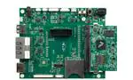
Get to Know the i.MX 6UltraLite EVK
Headphone
Output
Speaker
CAN
ON/OFF
Debug USB
Power Switch
Reset
MIC
DC IN: 5V/3.5A
Audio Codec
USB OTG
Boot Mode
Select Switch
USB HOST
DDR3L
JTAG
Arduino
i.MX 6UltraLite
Arduino
SODIMM
Interface
Ethernet x2
MicroSD/eMMC
Boot Device
Select Switch
HDMI*
LCD
EMV
Camera
SD
Figure 1: Front side main interfaces of i.MX 6UltraLite EVK
*Note: HDMI function validation ongoing. Contact Freescale.
4
�freescale.com
Set Up the Boards
1. Unpack the Kit
The evaluation kit is shipped with the following items:
Item
Description
CPU Board
Main board with i.MX 6UltraLite applications processor, memory, discrete power circuitry
and microSD card slot
Base Board
Peripherals and connectivity board
2. Prepare Accessories
The following items are required to run the i.MX 6UltraLite evaluation kit:
Item
Description
Power Supply
Output: 5V/3.5A, Plug: 2.1mmx5.5mm
USB Cable
USB cable (micro-B to standard-A)
MicroSD Card
Bootable Linux image (see the Download BSP Images section on how to load the image
on a MicroSD card)
LCD Module
(optional)
LCD8000-43T is the recommended module, which has a 4.3 inch resistive touch screen
Note: Power supply, USB cable, MicroSD card, LCD module are not included.
5
�Quick Start Guide
Set Up the Boards (cont.)
3. Download Software and Tools
Download installation software and documentation under “Jump Start Your Design” at
freescale.com/iMX6ULEVK. The following documents are available on the website:
Item
Description
Documentation
• Schematics, layout and Gerber files
• Quick Start Guide
Software
Development
Linux BSPs
Demo Images
Copy of the latest Linux BSP images that are available to program on to the MicroSD card
Set Up the System
1. Insert SD Card
• Insert the MicroSD card into socket J301 on the CPU board (700-28617).
Note: Pay careful attention to the microSD connector as it is fragile. Slide the
connector up or down, following the open and close arrows on the connector
in order to place the microSD card inside and lock it in place. See the
Getting Started Video at freescale.com/iMX6ULEVK for an example.
6
�freescale.com
2. Connect USB Debug Cable (optional)
• Connect the micro-B end of the USB cable into debug port J1901 on the base
board (700-28616). Connect the other end of the cable to a PC acting as a host
terminal. One UART connection will appear on the PC for debugging. If needed,
the Serial to USB drivers can be found at: silabs.com/products/mcu/
Pages/USBtoUARTBridgeVCPDrivers.aspx
• Open the terminal window (i.e. Hyper Terminal or TeraTerm) and apply the
following configuration:
Baud Rate: 115200
Data Bits: 8
Stop Bit: 1
Parity: None
Flow Control: None
3. Connect LCD Module (optional)
• Connect the FPC cable of LCD module (LCD8000-43T) to the LCD connector
J901 on the base board (700-28616) with the silver side of the cable facing down.
Note: The LCD Module is sold separately at freescale.com/iMX6ULEVK.
7
�Quick Start Guide
Set Up the System (cont.)
4. Connect Ethernet Cable (optional)
• Connect an Ethernet cable to the right port of the Ethernet Jack J1501
(close to the HDMI connector).
5. Connect Power Supply
• Connect the plug of the 5V power supply to the DC power jack J2001 on the
base board (700-28616) and slide the power switch SW2001 to ON. When the
power is connected to the i.MX 6UltraLite EVK, it will automatically begin the
boot sequence.
Boot Process for Linux Image
• During the boot process, there will be operating system status information
scrolling on the terminal window of the PC (if connected). The Linux penguin
images will initially appear in the upper left corner of the LCD screen.
• When the boot process is complete, the Linux operating system (Yocto Project)
will be displayed on the LCD screen.
To work from the terminal window on the host PC, press enter at the terminal window
to get the command prompt. Account name: root, password none.
8
�freescale.com
DIP Switch Configuration
The SW602 table shows the switch configuration of the boot mode for i.MX 6UltraLite
EVK. Internal Boot is chosen as the default.
The SW601 table shows the switch configuration of the boot device for i.MX 6UltraLite
EVK. MicroSD is chosen as the default.
i.MX 6UltraLite EVK DIP Switch Configuration (SW602)
D1/MODE1
D2/MODE0
Boot Mode
OFF
OFF
Boot From Fuses
OFF
ON
Serial Downloader
ON
OFF
Internal Boot
ON
ON
Reserved
i.MX 6UltraLite EVK DIP Switch Configuration (SW601)
D1
D2
D3
D4
OFF
OFF
ON
OFF
Boot Device
MicroSD
OFF
OFF
OFF
OFF
Quad SPI
OFF
ON
ON
OFF
eMMC
ON
ON
OFF
ON
NAND
Note: Bold indicates preferred configurations.
9
�Quick Start Guide
Button Functions
The button operations table shows the functions of the push buttons and switches
on the board.
Item
Description
SW2101
Evaluation board ON/OFF button
• In Yocto Project, a short press of the button will generate an interrupt that is defined
by the user.
• A prolonged press of the button (>5 sec) will force an immediate hardware shutdown.
• If board is in the SHUTDOWN state, a short press of the button will restart (boot)
the system.
• If the board is in the STANDBY state, a short press of the button will bring the system
out of standby (resume operations, no boot).
SW2102
Evaluation board RESET button
• A press of the button will reset the system and begin a boot sequence.
SW2001
Evaluation board power switch
• Switching to the ON position connects the 5V power supply to the EVK main
power system.
• Switching to the OFF position immediately removes all power from the board.
10
�freescale.com
Additional Reference
Download BSP Images
The board images can be downloaded to the target board by using the manufacturing
tool, named MFGTool, which runs on a computer with the Windows® operating system.
The MFGTool zip file can be found at freescale.com/iMX6ULEVK.
Perform the following steps to download the board images:
1. Unzip the MFGTool file to a selected location. The directory is named MFGTool-Dir
in this example.
2. If the MFGTool is a version with rootfs, you can skip to step 4.
3.
If the MFGTool is a version without rootfs, copy the following files from the demo
images packages to the “MFGTool-Dir/Profiles/Linux/OS Firmware/files” path,
make sure the file names are the same as the files listed below.
• u-boot-imx6ulevk_sd.imx
• zImage-imx6ul-14x14-evk.dtb
• zImage
• rootfs_nogpu.tar.bz2
4. Switch SW602 to OFF, ON
(from 1-2 bit) to enter serial download
mode as shown in Figure 2.
Figure 2: SW602 setting for Serial
Download Mode
11
�Quick Start Guide
Additional Reference (cont.)
5. Make sure the MicroSD card is inserted into socket J301 on the CPU board
(700-28617).
6. Connect the micro-B end of the USB cable into OTG port (J1102) on the base
board (700-28616). Connect the other end of the cable to a PC running Windows OS.
The i.MX 6UltraLite will be enumerated as a HID device on PC.
7. Connect the plug of the 5V power supply to the DC power jack J2001 on the base
board (700-28616). Then slide the power switch SW2001 to ON.
8. Double click the file *.vbs according to the target device as shown:
Target Boot Device
VBS file
SD Card (USDHC-1)
mfgtool2-yocto-mx-evk-sdcard-sd1.vbs
MicroSD Card (USDHC-2, default)
mfgtool2-yocto-mx-evk-sdcard-sd2.vbs
Quad SPI NOR Flash
mfgtool2-yocto-mx-evk-spi-nor.vbs
Note: MicroSD Card is the default setting.
12
�freescale.com
9. For example, we chose the MicroSD card (USDHC-2) as the boot device.
Double click mfgtool2-yocto-mx-evk-sdcard-sd2.vbs, and then click Start to start
downloading images.
Figure 3. Starting download
The process bar becomes green once the download is complete.
Figure 4. Download complete
10. Click Stop, then Exit.
13
�Quick Start Guide
14
�Get Started
Download installation software and documentation under at
freescale.com/iMX6ULEVK.
Support
Visit the i.MX community at imxcommunity.org.
Warranty
Visit freescale.com/warranty for complete
warranty information.
For more information, visit
freescale.com/iMX6ULEVK
Freescale and the Freescale logo are trademarks of Freescale Semiconductor,
Inc., Reg. U.S. Pat. & Tm. Off. All other product or service names are the
property of their respective owners. ARM is a registered trademark of ARM
Limited (or its subsidiaries) in the EU and/or elsewhere. All rights reserved.
© 2015 Freescale Semiconductor, Inc.
Document Number: IMX6ULTRALITEQSG REV 1
Agile Number: 926-28621 REV B
��
很抱歉,暂时无法提供与“MCIMX6UL-EVK”相匹配的价格&库存,您可以联系我们找货
免费人工找货- 国内价格 香港价格
- 1+1228.225031+158.93879