Quick Start Guide
i.MX 7ULP Evaluation Kit
Based on the i.MX 7ULP Applications Processor
�Quick Start Guide
GET TO KNOW THE EVALUATION KIT BASED ON THE i.MX 7ULP
APPLICATIONS PROCESSOR
MIPI-DSI
LCD
Connector
SD card
slot
Power
switch
HDMI connector
Touchscreen
Connector
DC Jack
Audio Jack
Speaker
connector
USB HSIC
WiFi/BT
Arduino
connector
Micro-SD Slot
LPDDR3
JTAG
connector
USB Type-C
ADC/DAC
connector
Debug Port
MFI
connector
User
buttons
Li-ion
Battery
socket
Tamper
switch
Figure 1: Main interfaces of i.MX 7ULP EVK
2
On/Off
button
RESET
button
� www.nxp.com
ABOUT THE EVALUATION KIT BASED ON i.MX 7ULP
The Evaluation Kit (EVK) based on the
i.MX 7ULP introduces developers to
the i.MX 7ULP applications processor.
The EVK enables HDMI output for
simple out-of-the-box bring up but
allows reconfiguration for MIPI displays.
The EVK is designed as a System-OnModule (SOM) board that connects to
an associated baseboard. The SOM
provides 1 GB LPDDR3, 8 MB Quad SPI
flash, Micro SD 3.0 card socket, Wi-Fi/
Bluetooth capability, USB 2.0 OTG
with Type C connector and an NXP
PF1550 power management IC (PMIC).
The baseboard provides additional
capabilities including a full SD/MMC
3.0 card socket, audio codec, multiple
sensors, an HDMI connector, and
an alternate MIPI display connector.
Additionally, the EVK facilitates software
development with the ultimate goal of
faster time to market through the support
of both Linux® OS and Android™ rich
operating systems, as well as FreeRTOS.
Hardware design files, tools and board
support packages (BSPs) for Linux®
and Android® are available at
www.nxp.com/iMX7ULPEVK.
3
�Quick Start Guide
FEATURES
The following features are available with the EVK based on the i.MX 7ULP applications
processor:
• i.MX 7ULP applications processor with
ARM® Cortex®-A7 core and ARM®
Cortex®-M4 core
• 1 GB LPDDR3 SDRAM
• 8 MB QSPI NOR Flash
• eMMC (unpopulated)
• Sensors including:
- Accelerometer / Magnetometer
- Pressure Sensor
- Gyroscope
• JTAG 20-pin 2.54 mm connector
• MicroSD® connector
• Debug port for ARM Cortex-A7/M4
core via USB micro-B connector
• Wi-Fi/BT
• Arduino connector
• USB Type-C connector
• SD connector
• MIPI-DSI LCD connector
• 3.5 mm audio stereo headphone jack
• USB HSIC I-PEX connector
• Tamper detect switch
• HDMI Output connector
• Speaker connectors
• Li-ion battery socket
4
� www.nxp.com
HOW TO GET STARTED
This section describes how to use the evaluation kit and the required accessories to
develop applications using the evaluation kit.
1
Unpacking
the Kit
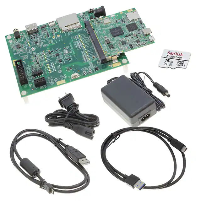
The evaluation kit is shipped with the
items listed in Table 1. Ensure the items
are available in the i.MX 7ULP Evaluation
Kit.
ITEM
SOM board
Base Board
DESCRIPTION
SOM board with i.MX 7ULP
applications processor,
LPDDR3, PMIC, WIFI/BT,
QSPI and MicroSD card slot
Peripherals and connectivity
board
Documentation
Quick Start Guide
Power Supply
Output: 5 V/4 A, Plug: 2.1
mm x 5.5 mm
USB Cable
USB cable (micro-B to
standard-A)
Micro-SD card
Bootable Linux image
Table 1: Contents of the i.MX 7ULP Evaluation Kit
�
2
Download Software
and Tools
Download installation software and
documentation under “Jump Start
Your Design” at www.nxp.com/
iMX7ULPEVK.
ITEM
Documentation
DESCRIPTION
• �Schematics, layout and
Gerber files
• Quick Start Guide
Software
development
tools
• Linux and Android BSPs
Demo images
Copy of the latest Linux and
Android BSP images that are
available to program on to
the MicroSD card
• FreeRTOS SDK
Table 2: Download Software and Tools Contents
5
�Quick Start Guide
SETTING UP THE SYSTEM
1
Insert MicroSD
Card
Insert the MicroSD card into socket J1 on
the SOM board (700-29163).
Open the terminal window (i.e., Hyper
Terminal or TeraTerm) and apply the
following configuration:
• Baud rate: 115200
• Data bits: 8
2
Connect USB
Debug Cable
Connect the micro-B end of the supplied
USB cable into debug port J6 on the
SOM board (700-29163). Connect the
other end of the cable to a PC acting as a
host terminal. If needed, the serial to USB
drivers can be found at www.silabs.com/
products/development-tools/software/
usb-to-uart-bridge-vcp-drivers
Once the PC recognizes the virtual USB
to UART device, it can be seen in your PC
Device Manager list.
There will be two ports automatically
configured: one is for the Cortex-A7 core
console/debug serial port, and the other
one is for the Cortex-M4 debug.
6
• Stop bit: 1
• Parity: None
• Flow control: None
3
Connect
Power Supply
IConnect the plug of the 5 V power
supply to the DC power jack P1 on base
board (700-29164) and slide power switch
SW1 to ON. When power is
connected to the EVK, it will automatically
begin the boot sequence.
� www.nxp.com
BOOT PROCESS FOR LINUX IMAGE
Boot Process
• Change SW1 on the SOM board (70029163) to ON, OFF, OFF, ON (from bits
4-1) to boot from the MicroSD card,
as shown in Figure 2. After the board
images are programmed and the boot
switches are correctly configured, the
system is ready to run.
• Power on the EVK board.
Figure 2. SW1 setting for internal boot mode
• During the boot process, there will be
operating system status information
scrolling on the terminal window of the
PC (if connected).
• When the boot process is complete,
the Linux operating system (Yocto
Project) will be displayed via HDMI
connector.
• To work from the terminal window
on the host PC, press ‘Enter’ at the
terminal window to get the command
prompt. Account name: root,
password none. For details on running
FreeRTOS™ on ARM Cortex-M4 core,
please visit www.nxp.com/iMXtools.
7
�Quick Start Guide
DIP SWITCH CONFIGURATION
Table 3 shows the switch configuration of
boot mode for i.MX 7ULP EVK. Dual boot
is chosen as default.
D4
D3
D2
D1
BOOT
MODE
ON
OFF
OFF
ON
Dual boot
OFF
OFF
OFF
ON
Single boot
X
ON
OFF
ON
Low power
boot
X
X
ON
OFF
Download
Table 3: i.MX 7ULP EVK DIP switch configuration (SW1
on SOM)
8
� www.nxp.com
BUTTON FUNCTIONS
Table 4 shows the functions of the push buttons and switches on the board.
ITEM
SW2 ON SOM
DESCRIPTION
Evaluation kit ON/OFF button
• �In Yocto Project, short press and long press will
only generate an interrupt, the usage is defined by
the application software.
• �Prolonged depress (>5 sec) will force an immediate
hardware shutdown.
• �If board is in the SHUTDOWN state, short press of
the button will restart (boot) the system.
• �If board is in the STANDBY state, short press of the
button will bring the system out of standby (resume
operations, no boot).
SW3 ON SOM
Evaluation kit RESET button
• �Button press will reset the system and begin a boot
sequence.
SW2 ON BB
Evaluation kit switch
• VOL+
SW3 ON BB
Evaluation kit switch
• VOLTable 4: i.MX 7ULP EVK board button operations
9
�Quick Start Guide
The following information is provided per Article 10.8 of the Radio Equipment Directive 2014/53/EU:
(a) Frequency bands in which the equipment operates.
(b) The maximum RF power transmitted.
PN
RF Technology
(a) Freq Ranges (EU)
WLAN 2.4GHz
Mode 802.11b/g/n
2412 MHz – 2472 MHz
(b) Max
Transmitted Power
WLAN 5GHz Mode
5180 MHz – 5825 MHz 16.92 dBm
MCIMX7ULP-EVK 802.11a/n/ac
WLAN 5.8GHz
Mode
5725 MHz – 5850 MHz
BT/ BLE
2402 MHz – 2480 MHz 7.79 dBm
EUROPEAN DECLARATION OF CONFORMITY
(Simplified DoC per Article 10.9 of the Radio Equipment Directive 2014/53/EU)
This apparatus, namely MCIMX7ULP-EVK, conforms to the Radio Equipment Directive 2014/53/EU.
The full EU Declaration of Conformity for this apparatus can be found at this location:
www.nxp.com/iMX7ULP
10
� www.nxp.com
This device complies with Part 15 of the FCC Rules. Operation is subject to the
following two conditions:
(1) This device may not cause harmful interference, and
(2) This device must accept any interference received, including interference that may
cause undesired operation.
Attention that changes or modification not expressly approved by the party
responsible for compliance could void the user’s authority to operate the equipment.
Note: This product has been tested and found to comply with the limits for a Class
B digital device, pursuant to Part 15 of the FCC Rules. These limits are designed to
provide reasonable protection against harmful interference in a residential installation.
This product generates, uses, and can radiate radio frequency energy and, if not
installed and used in accordance with the instructions, may cause harmful interference
to radio communications. However, there is no guarantee that interference will not
occur in a particular installation. If this product does cause harmful interference to
radio or television reception, which can be determined by turning the equipment off
and on, the user is encouraged to try to correct the interference by one or more of the
following measures:
—Reorient or relocate the receiving antenna.
—Increase the separation between the equipment and receiver.
—Connect the equipment into an outlet on a circuit different from that to which the
receiver is connected.
—Consult the dealer or an experienced radio/TV technician for help.
This equipment should be installed and operated with a minimum distance 20cm
between the radiator and your body
11
�SUPPORT
Visit www.nxp.com/support for a list
of phone numbers within your region.
WARRANTY
Visit www.nxp.com/warranty for
complete warranty information.
Get Started
Download installation
software and documentation
under “Jump Start Your Design”
at www.nxp.com/iMX7ULPEVK.
www.nxp.com
NXP and the NXP logo are trademarks of NXP B.V. All other product or service names are the property of
their respective owners. © 2018 NXP B.V.
Document Number: IMX7ULPWSG REV 0
Agile Number: 926-29162 REV A
�