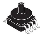
MPX10 Series
10 kPa Uncompensated Pressure Sensors
Rev. 15 — 22 April 2021
1
Product data sheet
General Description
The MPX10 series device is a silicon piezoresistive pressure sensor providing a very
accurate and linear voltage output directly proportional to the applied pressure. This
standard, low cost, uncompensated sensor permits manufacturers to design and
add their own external temperature compensation and signal conditioning networks.
Compensation techniques are simplified because of the predictability of NXP's single
element strain gauge design.
2
Features and Benefits
•
•
•
•
•
3
Low Cost
Patented Silicon Shear Stress Strain Gauge Design
Ratiometric to Supply Voltage
Differential and Gauge Options
Durable Epoxy Unibody Element or Thermoplastic (PPS) Surface Mount Package
Applications
•
•
•
•
•
•
•
•
Air Movement Control
Environmental Control Systems
Level Indicators
Leak Detection
Medical Diagnostics
Industrial Controls
Pneumatic Control Systems
Robotics
�MPX10 Series
NXP Semiconductors
10 kPa Uncompensated Pressure Sensors
4
Ordering Information
Table 1. Ordering information
Device Name
Package
options
Case
number
Number of ports
None
Single
Dual
Pressure type
Gauge
Device marking
Differential Absolute
Small outline package (MPX10 Series)
MPXV10GC6U
Rail
482A
●
●
MPXV10G
Unibody package (MPX10 Series)
MPX10D
Tray
344
MPX10DP
Tray
344C
MPX10GP
Tray
344B
●
●
●
●
●
MPX10D
●
MPX10DP
MPX10GP
Small outline package
MPXV10GC6U
Case 482A-01
Unibody packages
aaa-041242
MPX10D
Case 344-15
MPX10
Product data sheet
MPX10DP
Case 344C-01
All information provided in this document is subject to legal disclaimers.
Rev. 15 — 22 April 2021
aaa-041213
MPX10GP
Case 344B-01
© NXP B.V. 2021. All rights reserved.
2 / 20
�MPX10 Series
NXP Semiconductors
10 kPa Uncompensated Pressure Sensors
5
Block Diagram
Figure 1 shows a schematic of the internal circuitry on the stand-alone pressure sensor
chip.
Figure 1. Uncompensated pressure sensor schematic
6
Pin Information
6.1 MPXV10GC6U
5
4
6
3
7
2
8
1
aaa-038068
Figure 2. Case 482A-01
Table 2. Pin definitions - MPXV10GC6U
Symbol
MPX10
Product data sheet
Pin
Description
GND
1
Ground
+VOUT
2
+Voltage output
VS
3
Power supply
–VOUT
4
–Voltage output
n.c.
5
Not connected
n.c.
6
Not connected
n.c.
7
Not connected
n.c.
8
Not connected
All information provided in this document is subject to legal disclaimers.
Rev. 15 — 22 April 2021
© NXP B.V. 2021. All rights reserved.
3 / 20
�MPX10 Series
NXP Semiconductors
10 kPa Uncompensated Pressure Sensors
6.2 MPX10D
1
2
3
4
aaa-037831
Figure 3. Case 344-15
Table 3. Pin definitions - MPX10D
Symbol
Pin
Description
GND
1
Ground
+VOUT
2
+ Voltage output
VS
3
Power supply
–VOUT
4
– Voltage output
6.3 MPX10DP
1 2 3 4
aaa-037859
Figure 4. Case 344C-01
Table 4. Pin definitions - MPX10DP
MPX10
Product data sheet
Symbol
Pin
Description
GND
1
Ground
+VOUT
2
+ Voltage output
VS
3
Power supply
–VOUT
4
– Voltage output
All information provided in this document is subject to legal disclaimers.
Rev. 15 — 22 April 2021
© NXP B.V. 2021. All rights reserved.
4 / 20
�MPX10 Series
NXP Semiconductors
10 kPa Uncompensated Pressure Sensors
6.4 MPX10GP
4 3 2 1
aaa-037861
Figure 5. Case 344B-01
Table 5. Pin definitions - MPX10GP
MPX10
Product data sheet
Symbol
Pin
Description
GND
1
Ground
+VOUT
2
+ Voltage output
VS
3
Power supply
–VOUT
4
– Voltage output
All information provided in this document is subject to legal disclaimers.
Rev. 15 — 22 April 2021
© NXP B.V. 2021. All rights reserved.
5 / 20
�MPX10 Series
NXP Semiconductors
10 kPa Uncompensated Pressure Sensors
7
Maximum Ratings
Table 6. Maximum ratings
Exposure beyond the specified limits may cause permanent damage or degradation to the device.
In accordance with the Absolute Maximum Rating System (IEC 60134).
Symbol
Parameter
Conditions
Min
Typ
Max
Unit
Pmax
Overpressure
P1 > P2
—
—
75
kPa
Pburst
Burst Pressure
P1 > P2
—
—
100
kPa
Tstg
Storage Temperature
−40
—
+125
°C
TA
Operating Temperature
−40
—
+125
°C
MPX10
Product data sheet
All information provided in this document is subject to legal disclaimers.
Rev. 15 — 22 April 2021
© NXP B.V. 2021. All rights reserved.
6 / 20
�MPX10 Series
NXP Semiconductors
10 kPa Uncompensated Pressure Sensors
8
Operating Characteristics
Table 7. Operating Characteristics (VS = 3.0 Vdc, TA = 25 °C unless otherwise noted, P1 > P2)
Characteristic
Symbol
Min
Typ
Max
Unit
Operating Pressure Range
[1]
POP
0
—
10
kPa
Supply Voltage
[2]
VS
—
3.0
6.0
VDC
Supply Current
Io
—
6.0
—
mAdc
Full Scale Span
[3]
VFSS
20
35
50
mV
Offset
[4]
Voff
0
20
35
mV
Sensitivity
ΔV/ΔP
—
3.5
—
mV/kPa
Linearity
[5]
—
−1.0
—
1.0
%VFSS
Pressure Hysteresis (0 kPa to 10 kPa)
[5]
—
—
±0.1
—
%VFSS
Temperature Hysteresis (−40 °C to +125 °C)
[5]
—
—
±0.5
—
%VFSS
Temperature Coefficient of Full Scale Span
[5]
TCVFSS
−0.22
—
−0.16
%VFSS/°C
Temperature Coefficient of Offset
[5]
TCVoff
—
±15
—
μV/°C
Temperature Coefficient of Resistance
[5]
TCR
0.21
—
0.27
%Zin/°C
Zin
400
—
550
Ω
Input Impedance
Output Impedance
Zout
750
—
1250
Ω
Response Time (10% to 90%)
[6]
tR
—
1.0
—
ms
Warm-Up Time
[7]
—
—
20
—
ms
Offset Stability
[8]
—
—
±0.5
—
%VFSS
[1]
[2]
[3]
[4]
[5]
[6]
[7]
[8]
1.0 kPa equals 0.145 PSI.
Device is ratiometric within this specified excitation range. Operating the device above the specified excitation range may induce additional error due to
device self-heating.
Full Scale Span (VFSS) is defined as the algebraic difference between the output voltage at full rated pressure and the output voltage at the minimum rated
pressure.
Offset (Voff) is defined as the output voltage at the minimum rated pressure.
Accuracy (error budget) consists of the following:
• Linearity: Output deviation from a straight line relationship with pressure, using the end point method, over the specified pressure range.
• Temperature Hysteresis: Output deviation at any temperature within the operating temperature range, after the temperature is cycled to and from the
minimum or maximum operating temperature points, with zero differential pressure applied.
• Pressure Hysteresis: Output deviation at any pressure within the specified range, when this pressure is cycled to and from the minimum or maximum
rated pressure, at 25 °C.
• TcSpan: Output deviation at full rated pressure over the temperature range of 0 °C to 85 °C, relative to 25 °C
• TcOffset: Output deviation with minimum rated pressure applied, over the temperature range of 0 °C to 85 °C, relative to 25 °C
• TCR: Zin deviation with minimum rated pressure applied, over the temperature range of −40 °C to +125 °C, relative to 25 °C
Response Time is defined as the time for the incremental change in the output to go from 10% to 90% of its final value when subjected to a specified step
change in pressure.
Warm-Up Time is defined as the time required for the product to meet the specified output voltage after the pressure has been stabilized.
Offset Stability is the product’s output deviation when subjected to 1000 hours of Pulsed Pressure Temperature Cycling with Bias test.
MPX10
Product data sheet
All information provided in this document is subject to legal disclaimers.
Rev. 15 — 22 April 2021
© NXP B.V. 2021. All rights reserved.
7 / 20
�MPX10 Series
NXP Semiconductors
10 kPa Uncompensated Pressure Sensors
9
Characteristics
9.1 Voltage output versus applied differential pressure
The output voltage of the differential or gauge sensor increases with increasing pressure
applied to the pressure side (P1) relative to the vacuum side (P2). Similarly, output
voltage increases as increasing vacuum is applied to the vacuum side (P2) relative to the
pressure side (P1).
9.2 Temperature compensation
Figure 6 shows the typical output characteristics of the MPX10 series over temperature.
Because this strain gauge is an integral part of the silicon diaphragm, there are no
temperature effects due to differences in the thermal expansion of the strain gauge and
the diaphragm, as are often encountered in bonded strain gauge pressure sensors.
However, the properties of the strain gauge itself are temperature dependent, requiring
that the device be temperature compensated if it is to be used over an extensive
temperature range.
Temperature compensation and offset calibration can be achieved rather simply with
additional resistive components, or by designing your system using the MPX2010 series
sensor.
Several approaches to external temperature compensation over both −40 °C to +125 °C
and 0 °C to +80 °C ranges are presented in Application Note AN840
Figure 6. Output vs. pressure differential
9.3 Linearity
Linearity refers to how well a transducer's output follows the equation
Vout = Voff + Sensitivity x P over the operating pressure range (Figure 7). There are two
basic methods for calculating nonlinearity:
• End point straight line fit
MPX10
Product data sheet
All information provided in this document is subject to legal disclaimers.
Rev. 15 — 22 April 2021
© NXP B.V. 2021. All rights reserved.
8 / 20
�MPX10 Series
NXP Semiconductors
10 kPa Uncompensated Pressure Sensors
• Least squares best line fit
While a least squares fit gives the "best case" linearity error (lower numerical value), the
calculations required are burdensome.
Conversely, an end point fit will give the "worst case" error (often more desirable in error
budget calculations) and the calculations are more straightforward for the user.
NXP's specified pressure sensor linearities are based on the end point straight line
method measured at the midrange pressure.
Least
Square
Deviation
Least Squares Fit
Relative Voltage Output
Exaggerated
Performance
Curve
Straight Line
Deviation
End Point Straight
Line Fit
Offset
0
50
100
Pressure (% Full Scale)
aaa-038501
Figure 7. Linearity specification comparison
9.4 Pressure (P1) / Vacuum (P2) side identification
NXP designates the two sides of the pressure sensor as the Pressure (P1) side and the
Vacuum (P2) side. The Pressure (P1) side is the side containing silicone gel that isolates
the die from the environment. The NXP MPX pressure sensor is designed to operate with
positive differential pressure applied, P1 > P2.
The Pressure (P1) side may be identified by using Table 8.
Table 8. Pressure (P1) side delineation table
Part Number
Case Type
Pressure (P1) Side Identifier
MPX10D
344
Stainless Steel Cap
MPX10DP
344C
Side with Part Marking
MPX10GP
344B
Side with Port Attached
MPXV10GC6U
482A
Side with Port Attached
9.5 Media compatibility
Figure 8 illustrates the differential or gauge configuration in a typical chip carrier. A
silicone gel isolates the die surface and wire bonds from the environment while allowing
the pressure signal to be transmitted to the silicon diaphragm.
MPX10
Product data sheet
All information provided in this document is subject to legal disclaimers.
Rev. 15 — 22 April 2021
© NXP B.V. 2021. All rights reserved.
9 / 20
�MPX10 Series
NXP Semiconductors
10 kPa Uncompensated Pressure Sensors
The MPX10 series pressure sensor operating characteristics, internal reliability and
qualification tests are based on the use of dry clean air as the pressure medium. Media
other than dry clean air may have adverse effects on sensor performance and long
term reliability. Contact the factory for information regarding media compatibility in your
application.
For more information, refer to application note AN3728.
silicone
die coat
stainless steel
metal cover
die
epoxy
case
P1
wire bond
lead frame
P2
RTV die
bond
aaa-037713
Figure 8. Unibody package — cross-sectional diagram (not to scale)
MPX10
Product data sheet
All information provided in this document is subject to legal disclaimers.
Rev. 15 — 22 April 2021
© NXP B.V. 2021. All rights reserved.
10 / 20
�MPX10 Series
NXP Semiconductors
10 kPa Uncompensated Pressure Sensors
10 Package Outlines
Package dimensions are provided in package drawings. To find the most current package
outline drawing, go to https://www.nxp.com/ and perform a keyword search for the
drawing's document number.
10.1 Small outline packages
Figure 9. SOT1854-1 (Case 482A) - Page 1
MPX10
Product data sheet
All information provided in this document is subject to legal disclaimers.
Rev. 15 — 22 April 2021
© NXP B.V. 2021. All rights reserved.
11 / 20
�MPX10 Series
NXP Semiconductors
10 kPa Uncompensated Pressure Sensors
Figure 10. SOT1854-1 (Case 482A) - Page 2
MPX10
Product data sheet
All information provided in this document is subject to legal disclaimers.
Rev. 15 — 22 April 2021
© NXP B.V. 2021. All rights reserved.
12 / 20
�MPX10 Series
NXP Semiconductors
10 kPa Uncompensated Pressure Sensors
10.2 Unibody packages
Figure 11. SOT1753-1 (Case 344B-01)
MPX10
Product data sheet
All information provided in this document is subject to legal disclaimers.
Rev. 15 — 22 April 2021
© NXP B.V. 2021. All rights reserved.
13 / 20
�MPX10 Series
NXP Semiconductors
10 kPa Uncompensated Pressure Sensors
Figure 12. SOT1754-1 (Case 344C-01)
MPX10
Product data sheet
All information provided in this document is subject to legal disclaimers.
Rev. 15 — 22 April 2021
© NXP B.V. 2021. All rights reserved.
14 / 20
�MPX10 Series
NXP Semiconductors
10 kPa Uncompensated Pressure Sensors
Figure 13. SOT1772-1 (Case 344-15)
MPX10
Product data sheet
All information provided in this document is subject to legal disclaimers.
Rev. 15 — 22 April 2021
© NXP B.V. 2021. All rights reserved.
15 / 20
�MPX10 Series
NXP Semiconductors
10 kPa Uncompensated Pressure Sensors
11 References
[1]
AN840 – Temperature Compensation Methods For The Motorola X-ducer Pressure Sensor Element
https://www.nxp.com/docs/en/application-note/AN840.pdf
[2]
AN1984 – Handling Freescale Pressure Sensors
https://www.nxp.com/docs/en/application-note/AN1984.pdf
[3]
AN3150 – Soldering Recommendations for Pressure Sensor Devices
https://www.nxp.com/docs/en/application-note/AN3150.pdf
[4]
AN1318 Interfacing Semiconductor Pressure Sensors to Microcomputers
https://www.nxp.com/docs/en/application-note/AN1318.pdf
[5]
AN3728 Media Compatibility for IPS PRT Pressure Sensors
https://www.nxp.com/docs/en/application-note/AN3728.pdf
12 Revision history
Table 9. Revision history
Document ID
Release date
Data sheet status
Change notice
Supersedes
MPX10 v.15
20210422
Product data sheet
-
MPX10 v.14
Modifications
• Redesigned the data sheet to comply with the new identity guidelines of NXP
Semiconductors. Adapted legal texts to the new company name where appropriate.
• Removed the following discontinued part numbers throughout: MPXV10GC7U
MPX10 v.14
200810
MPX10
Product data sheet
Product data sheet
-
All information provided in this document is subject to legal disclaimers.
Rev. 15 — 22 April 2021
MPX10 v.13
© NXP B.V. 2021. All rights reserved.
16 / 20
�MPX10 Series
NXP Semiconductors
10 kPa Uncompensated Pressure Sensors
13 Legal information
13.1 Data sheet status
Document status
[1][2]
Product status
[3]
Definition
Objective [short] data sheet
Development
This document contains data from the objective specification for product
development.
Preliminary [short] data sheet
Qualification
This document contains data from the preliminary specification.
Product [short] data sheet
Production
This document contains the product specification.
[1]
[2]
[3]
Please consult the most recently issued document before initiating or completing a design.
The term 'short data sheet' is explained in section "Definitions".
The product status of device(s) described in this document may have changed since this document was published and may differ in case of multiple
devices. The latest product status information is available on the Internet at URL http://www.nxp.com.
notice. This document supersedes and replaces all information supplied prior
to the publication hereof.
13.2 Definitions
Draft — A draft status on a document indicates that the content is still
under internal review and subject to formal approval, which may result
in modifications or additions. NXP Semiconductors does not give any
representations or warranties as to the accuracy or completeness of
information included in a draft version of a document and shall have no
liability for the consequences of use of such information.
Short data sheet — A short data sheet is an extract from a full data sheet
with the same product type number(s) and title. A short data sheet is
intended for quick reference only and should not be relied upon to contain
detailed and full information. For detailed and full information see the
relevant full data sheet, which is available on request via the local NXP
Semiconductors sales office. In case of any inconsistency or conflict with the
short data sheet, the full data sheet shall prevail.
Product specification — The information and data provided in a Product
data sheet shall define the specification of the product as agreed between
NXP Semiconductors and its customer, unless NXP Semiconductors and
customer have explicitly agreed otherwise in writing. In no event however,
shall an agreement be valid in which the NXP Semiconductors product
is deemed to offer functions and qualities beyond those described in the
Product data sheet.
13.3 Disclaimers
Limited warranty and liability — Information in this document is believed
to be accurate and reliable. However, NXP Semiconductors does not
give any representations or warranties, expressed or implied, as to the
accuracy or completeness of such information and shall have no liability
for the consequences of use of such information. NXP Semiconductors
takes no responsibility for the content in this document if provided by an
information source outside of NXP Semiconductors. In no event shall NXP
Semiconductors be liable for any indirect, incidental, punitive, special or
consequential damages (including - without limitation - lost profits, lost
savings, business interruption, costs related to the removal or replacement
of any products or rework charges) whether or not such damages are based
on tort (including negligence), warranty, breach of contract or any other
legal theory. Notwithstanding any damages that customer might incur for
any reason whatsoever, NXP Semiconductors’ aggregate and cumulative
liability towards customer for the products described herein shall be limited
in accordance with the Terms and conditions of commercial sale of NXP
Semiconductors.
Right to make changes — NXP Semiconductors reserves the right to
make changes to information published in this document, including without
limitation specifications and product descriptions, at any time and without
MPX10
Product data sheet
Suitability for use — NXP Semiconductors products are not designed,
authorized or warranted to be suitable for use in life support, life-critical or
safety-critical systems or equipment, nor in applications where failure or
malfunction of an NXP Semiconductors product can reasonably be expected
to result in personal injury, death or severe property or environmental
damage. NXP Semiconductors and its suppliers accept no liability for
inclusion and/or use of NXP Semiconductors products in such equipment or
applications and therefore such inclusion and/or use is at the customer’s own
risk.
Applications — Applications that are described herein for any of these
products are for illustrative purposes only. NXP Semiconductors makes
no representation or warranty that such applications will be suitable
for the specified use without further testing or modification. Customers
are responsible for the design and operation of their applications and
products using NXP Semiconductors products, and NXP Semiconductors
accepts no liability for any assistance with applications or customer product
design. It is customer’s sole responsibility to determine whether the NXP
Semiconductors product is suitable and fit for the customer’s applications
and products planned, as well as for the planned application and use of
customer’s third party customer(s). Customers should provide appropriate
design and operating safeguards to minimize the risks associated with
their applications and products. NXP Semiconductors does not accept any
liability related to any default, damage, costs or problem which is based
on any weakness or default in the customer’s applications or products, or
the application or use by customer’s third party customer(s). Customer is
responsible for doing all necessary testing for the customer’s applications
and products using NXP Semiconductors products in order to avoid a
default of the applications and the products or of the application or use by
customer’s third party customer(s). NXP does not accept any liability in this
respect.
Limiting values — Stress above one or more limiting values (as defined in
the Absolute Maximum Ratings System of IEC 60134) will cause permanent
damage to the device. Limiting values are stress ratings only and (proper)
operation of the device at these or any other conditions above those
given in the Recommended operating conditions section (if present) or the
Characteristics sections of this document is not warranted. Constant or
repeated exposure to limiting values will permanently and irreversibly affect
the quality and reliability of the device.
Terms and conditions of commercial sale — NXP Semiconductors
products are sold subject to the general terms and conditions of commercial
sale, as published at http://www.nxp.com/profile/terms, unless otherwise
agreed in a valid written individual agreement. In case an individual
agreement is concluded only the terms and conditions of the respective
agreement shall apply. NXP Semiconductors hereby expressly objects to
applying the customer’s general terms and conditions with regard to the
purchase of NXP Semiconductors products by customer.
All information provided in this document is subject to legal disclaimers.
Rev. 15 — 22 April 2021
© NXP B.V. 2021. All rights reserved.
17 / 20
�MPX10 Series
NXP Semiconductors
10 kPa Uncompensated Pressure Sensors
No offer to sell or license — Nothing in this document may be interpreted
or construed as an offer to sell products that is open for acceptance or
the grant, conveyance or implication of any license under any copyrights,
patents or other industrial or intellectual property rights.
Export control — This document as well as the item(s) described herein
may be subject to export control regulations. Export might require a prior
authorization from competent authorities.
applications and products. Customer’s responsibility also extends to other
open and/or proprietary technologies supported by NXP products for use
in customer’s applications. NXP accepts no liability for any vulnerability.
Customer should regularly check security updates from NXP and follow up
appropriately. Customer shall select products with security features that best
meet rules, regulations, and standards of the intended application and make
the ultimate design decisions regarding its products and is solely responsible
for compliance with all legal, regulatory, and security related requirements
concerning its products, regardless of any information or support that may
be provided by NXP. NXP has a Product Security Incident Response Team
(PSIRT) (reachable at PSIRT@nxp.com) that manages the investigation,
reporting, and solution release to security vulnerabilities of NXP products.
Translations — A non-English (translated) version of a document is for
reference only. The English version shall prevail in case of any discrepancy
between the translated and English versions.
13.4 Trademarks
Quick reference data — The Quick reference data is an extract of the
product data given in the Limiting values and Characteristics sections of this
document, and as such is not complete, exhaustive or legally binding.
Security — Customer understands that all NXP products may be subject
to unidentified or documented vulnerabilities. Customer is responsible
for the design and operation of its applications and products throughout
their lifecycles to reduce the effect of these vulnerabilities on customer’s
MPX10
Product data sheet
Notice: All referenced brands, product names, service names and
trademarks are the property of their respective owners.
NXP — wordmark and logo are trademarks of NXP B.V.
All information provided in this document is subject to legal disclaimers.
Rev. 15 — 22 April 2021
© NXP B.V. 2021. All rights reserved.
18 / 20
�MPX10 Series
NXP Semiconductors
10 kPa Uncompensated Pressure Sensors
Tables
Tab. 1.
Tab. 2.
Tab. 3.
Tab. 4.
Tab. 5.
Tab. 6.
Ordering information ..........................................2
Pin definitions - MPXV10GC6U ........................ 3
Pin definitions - MPX10D .................................. 4
Pin definitions - MPX10DP ................................4
Pin definitions - MPX10GP ............................... 5
Maximum ratings ...............................................6
Tab. 7.
Tab. 8.
Tab. 9.
Operating Characteristics (VS = 3.0 Vdc,
TA = 25 °C unless otherwise noted, P1 >
P2) ..................................................................... 7
Pressure (P1) side delineation table ................. 9
Revision history ...............................................16
Figures
Fig. 1.
Fig. 2.
Fig. 3.
Fig. 4.
Fig. 5.
Fig. 6.
Fig. 7.
Uncompensated pressure sensor
schematic .......................................................... 3
Case 482A-01 ................................................... 3
Case 344-15 ......................................................4
Case 344C-01 ................................................... 4
Case 344B-01 ................................................... 5
Output vs. pressure differential ......................... 8
Linearity specification comparison .................... 9
MPX10
Product data sheet
Fig. 8.
Fig. 9.
Fig. 10.
Fig. 11.
Fig. 12.
Fig. 13.
Unibody package — cross-sectional
diagram (not to scale) ..................................... 10
SOT1854-1 (Case 482A) - Page 1 ..................11
SOT1854-1 (Case 482A) - Page 2 ..................12
SOT1753-1 (Case 344B-01) ........................... 13
SOT1754-1 (Case 344C-01) ........................... 14
SOT1772-1 (Case 344-15) ..............................15
All information provided in this document is subject to legal disclaimers.
Rev. 15 — 22 April 2021
© NXP B.V. 2021. All rights reserved.
19 / 20
�MPX10 Series
NXP Semiconductors
10 kPa Uncompensated Pressure Sensors
Contents
1
2
3
4
5
6
6.1
6.2
6.3
6.4
7
8
9
9.1
9.2
9.3
9.4
9.5
10
10.1
10.2
11
12
13
General Description ............................................ 1
Features and Benefits ........................................ 1
Applications .........................................................1
Ordering Information .......................................... 2
Block Diagram .....................................................3
Pin Information ....................................................3
MPXV10GC6U ...................................................3
MPX10D .............................................................4
MPX10DP .......................................................... 4
MPX10GP .......................................................... 5
Maximum Ratings ............................................... 6
Operating Characteristics .................................. 7
Characteristics .................................................... 8
Voltage output versus applied differential
pressure ............................................................. 8
Temperature compensation ............................... 8
Linearity ............................................................. 8
Pressure (P1) / Vacuum (P2) side
identification ....................................................... 9
Media compatibility ............................................ 9
Package Outlines .............................................. 11
Small outline packages ....................................11
Unibody packages ........................................... 13
References ......................................................... 16
Revision history ................................................ 16
Legal information .............................................. 17
Please be aware that important notices concerning this document and the product(s)
described herein, have been included in section 'Legal information'.
© NXP B.V. 2021.
All rights reserved.
For more information, please visit: http://www.nxp.com
For sales office addresses, please send an email to: salesaddresses@nxp.com
Date of release: 22 April 2021
Document identifier: MPX10
�