MC9S12XHY256
Reference Manual
Covers MC9S12XHY Family
Data Sheet: Advance Information
This document contains information on a new product. Specifications and information here in are subject to change without notice.
S12
Microcontrollers
MC9S12XHY256RMV1
Rev. 1.04
06/2013
freescale.com
�To provide the most up-to-date information, the revision of our documents on the World Wide Web will be
the most current. Your printed copy may be an earlier revision. To verify you have the latest information
available, refer to:
freescale.com/
A full list of family members and options is included in the appendices.
The following revision history table summarizes changes contained in this document.
This document contains information for all constituent modules, with the exception of the CPU. For CPU
information please refer to CPU12-1 in the CPU12 & CPU12X Reference Manual.
Revision History
Revision
Level
Description
Mar,25,2011
1.01
update Appendix electrical parameter value
Table A-11., “Pseudo Stop and Full Stop Current,
Table A-9., “Module Run Supply Currents
Table A-6., “5-V I/O Characteristics, item 4b
update Appendix, change classifications or conditions
Table A-6., “5-V I/O Characteristics, item 4b, change from 80c to 150c
Table A-11., “Pseudo Stop and Full Stop Current,item 11b,change from P to C
fix typo Table A-6., “5-V I/O Characteristics, 11 and 12, resistance not current
May,09,2011
1.02
fix typo on Table 1-7,it is LQFP112 and LQFP100
May,13,2011
1.03
fix typo on Section 1.7.3.42, “PU[4] / IOC0_2 / M1C0M / M1COSM— Port U
I/O Pin [4],it is M1COSM
fix on Section Table A-12., “ATD Operating Characteristics,∆VDDX=-0.1v
1.04
update block version ADC1.06, MSCAN3.13, PWM1.1, BDM2.02, DBG3.26,
CRG2.01, INT2.07,FTMR256,FTMR128
add STOP/WAIT feature for Section Table 1-11., “Interrupt Vector Locations;
update FSL link; fix typo of unit at Table A-7, Table A-8, Table A-21, A.1.10.1,
A.1.10.2, A.1.10.3, Table A-10, Table A-14, Table A-15, A.3.1.15,Table A-16,
Table A-22, Table A-26, Table 1-1;
updateInstantaneous maximum current at Table A-1
fix reference link at 1.9 Modes of Operation and 1.10 Security
update Table A-6./A-725, leackage current
Date
Jun,27,2013
�How to Reach Us:
Information in this document is provided solely to enable system and software
Home Page:
freescale.com
implementers to use Freescale products. There are no express or implied copyright
Web Support:
freescale.com/support
information in this document.
licenses granted hereunder to design or fabricate any integrated circuits based on the
Freescale reserves the right to make changes without further notice to any products
herein. Freescale makes no warranty, representation, or guarantee regarding the
suitability of its products for any particular purpose, nor does Freescale assume any
liability arising out of the application or use of any product or circuit, and specifically
disclaims any and all liability, including without limitation consequential or incidental
damages. “Typical” parameters that may be provided in Freescale data sheets and/or
specifications can and do vary in different applications, and actual performance may
vary over time. All operating parameters, including “typicals,” must be validated for each
customer application by customer’s technical experts. Freescale does not convey any
license under its patent rights nor the rights of others. Freescale sells products
pursuant to standard terms and conditions of sale, which can be found at the following
address: freescale.com/SalesTermsandConditions
Freescale and the Freescale logo are trademarks of Freescale Semiconductor, Inc.,
Reg. U.S. Pat. & Tm. Off. All other product or service names are the property of their
respective owners.
© 2011, 2013 Freescale Semiconductor, Inc.
Document Number: MC9S12XHY256RMV1
06/2013
�MC9S12XHY-Family Reference Manual, Rev. 1.04
4
Freescale Semiconductor
�Chapter 1
Device Overview MC9S12XHY-Family . . . . . . . . . . . . . . . . . . . . . . . . . . . . . . . 13
Chapter 2
Port Integration Module (S12XHYPIMV1) . . . . . . . . . . . . . . . . . . . . . . . . . . . . 65
Chapter 3
Memory Mapping Control (S12XMMCV4) . . . . . . . . . . . . . . . . . . . . . . . . . . . 157
Chapter 4
Interrupt (S12XINTV2) . . . . . . . . . . . . . . . . . . . . . . . . . . . . . . . . . . . . . . . . . . 181
Chapter 5
Background Debug Module (S12XBDMV2) . . . . . . . . . . . . . . . . . . . . . . . . . 199
Chapter 6
S12X Debug (S12XDBGV3) Module . . . . . . . . . . . . . . . . . . . . . . . . . . . . . . . . 225
Chapter 7
S12XE Clocks and Reset Generator (S12XECRGV2) . . . . . . . . . . . . . . . . . 261
Chapter 8
Pierce Oscillator (S12XOSCLCPV2) . . . . . . . . . . . . . . . . . . . . . . . . . . . . . . . 291
Chapter 9
Voltage Regulator (S12VREGL3V3V1). . . . . . . . . . . . . . . . . . . . . . . . . . . . . . 295
Chapter 10
Analog-to-Digital Converter (ADC12B12CV1) . . . . . . . . . . . . . . . . . . . . . . . 313
Chapter 11
Freescale’s Scalable Controller Area Network (S12MSCANV3) . . . . . . . . . 339
Chapter 12
Inter-Integrated Circuit (IICV3) . . . . . . . . . . . . . . . . . . . . . . . . . . . . . . . . . . . 393
Chapter 13
Pulse-Width Modulator (S12PWM8B8CV1) . . . . . . . . . . . . . . . . . . . . . . . . . . 421
Chapter 14
Serial Communication Interface (S12SCIV5) . . . . . . . . . . . . . . . . . . . . . . . . 453
Chapter 15
Serial Peripheral Interface (S12SPIV5) . . . . . . . . . . . . . . . . . . . . . . . . . . . . . 491
Chapter 16
Timer Module (TIM16B8CV2) . . . . . . . . . . . . . . . . . . . . . . . . . . . . . . . . . . . . . 517
MC9S12XHY-Family Reference Manual, Rev. 1.04
Freescale Semiconductor
5
�Chapter 17
Liquid Crystal Display (LCD40F4BV2) . . . . . . . . . . . . . . . . . . . . . . . . . . . . . 545
Chapter 18
256 KByte Flash Module (S12XFTMR256K1V1) . . . . . . . . . . . . . . . . . . . . . . 567
Chapter 19
128 KByte Flash Module (S12XFTMR128K1V1) . . . . . . . . . . . . . . . . . . . . . . 617
Chapter 20
Motor Controller (MC10B8CV1) . . . . . . . . . . . . . . . . . . . . . . . . . . . . . . . . . . . 667
Chapter 21
Stepper Stall Detector (SSDV1) . . . . . . . . . . . . . . . . . . . . . . . . . . . . . . . . . . . 699
Appendix A
Electrical Characteristics . . . . . . . . . . . . . . . . . . . . . . . . . . . . . . . . . . . . . . . . 717
Appendix B
Package and Die Information . . . . . . . . . . . . . . . . . . . . . . . . . . . . . . . . . . . . . 758
Appendix C
PCB Layout Guidelines. . . . . . . . . . . . . . . . . . . . . . . . . . . . . . . . . . . . . . . . . . 765
Appendix D
Derivative Differences. . . . . . . . . . . . . . . . . . . . . . . . . . . . . . . . . . . . . . . . . . . 768
Appendix E
Detailed Register Address Map . . . . . . . . . . . . . . . . . . . . . . . . . . . . . . . . . . . 768
Appendix F
Ordering Information. . . . . . . . . . . . . . . . . . . . . . . . . . . . . . . . . . . . . . . . . . . . 799
MC9S12XHY-Family Reference Manual, Rev. 1.04
6
Freescale Semiconductor
�Chapter 1
Device Overview MC9S12XHY-Family
1.1
1.2
1.3
1.4
1.5
1.6
1.7
1.8
1.9
1.10
1.11
1.12
1.13
1.14
1.15
1.16
1.17
Introduction . . . . . . . . . . . . . . . . . . . . . . . . . . . . . . . . . . . . . . . . . . . . . . . . . . . . . . . . . . . . . . . . . . 13
Features . . . . . . . . . . . . . . . . . . . . . . . . . . . . . . . . . . . . . . . . . . . . . . . . . . . . . . . . . . . . . . . . . . . . . 13
Module Features . . . . . . . . . . . . . . . . . . . . . . . . . . . . . . . . . . . . . . . . . . . . . . . . . . . . . . . . . . . . . . . 15
Block Diagram . . . . . . . . . . . . . . . . . . . . . . . . . . . . . . . . . . . . . . . . . . . . . . . . . . . . . . . . . . . . . . . . 22
Device Memory Map . . . . . . . . . . . . . . . . . . . . . . . . . . . . . . . . . . . . . . . . . . . . . . . . . . . . . . . . . . . 23
Part ID Assignments . . . . . . . . . . . . . . . . . . . . . . . . . . . . . . . . . . . . . . . . . . . . . . . . . . . . . . . . . . . . 27
Signal Description . . . . . . . . . . . . . . . . . . . . . . . . . . . . . . . . . . . . . . . . . . . . . . . . . . . . . . . . . . . . . 27
System Clock Description . . . . . . . . . . . . . . . . . . . . . . . . . . . . . . . . . . . . . . . . . . . . . . . . . . . . . . . 51
Modes of Operation . . . . . . . . . . . . . . . . . . . . . . . . . . . . . . . . . . . . . . . . . . . . . . . . . . . . . . . . . . . . 52
Security . . . . . . . . . . . . . . . . . . . . . . . . . . . . . . . . . . . . . . . . . . . . . . . . . . . . . . . . . . . . . . . . . . . . . . 55
Resets and Interrupts . . . . . . . . . . . . . . . . . . . . . . . . . . . . . . . . . . . . . . . . . . . . . . . . . . . . . . . . . . . 55
COP Configuration . . . . . . . . . . . . . . . . . . . . . . . . . . . . . . . . . . . . . . . . . . . . . . . . . . . . . . . . . . . . . 60
ATD External Trigger Input Connection . . . . . . . . . . . . . . . . . . . . . . . . . . . . . . . . . . . . . . . . . . . . 60
ATD Channel[17] Connection . . . . . . . . . . . . . . . . . . . . . . . . . . . . . . . . . . . . . . . . . . . . . . . . . . . . 61
VREG Configuration . . . . . . . . . . . . . . . . . . . . . . . . . . . . . . . . . . . . . . . . . . . . . . . . . . . . . . . . . . . 61
Oscillator Configuration . . . . . . . . . . . . . . . . . . . . . . . . . . . . . . . . . . . . . . . . . . . . . . . . . . . . . . . . . 61
Documentation Note . . . . . . . . . . . . . . . . . . . . . . . . . . . . . . . . . . . . . . . . . . . . . . . . . . . . . . . . . . . 62
Chapter 2
Port Integration Module (S12XHYPIMV1)
2.1
2.2
2.3
2.4
2.5
Introduction . . . . . . . . . . . . . . . . . . . . . . . . . . . . . . . . . . . . . . . . . . . . . . . . . . . . . . . . . . . . . . . . . . 66
External Signal Description . . . . . . . . . . . . . . . . . . . . . . . . . . . . . . . . . . . . . . . . . . . . . . . . . . . . . . 67
Memory Map and Register Definition . . . . . . . . . . . . . . . . . . . . . . . . . . . . . . . . . . . . . . . . . . . . . . 74
Functional Description . . . . . . . . . . . . . . . . . . . . . . . . . . . . . . . . . . . . . . . . . . . . . . . . . . . . . . . . . 150
Initialization Information . . . . . . . . . . . . . . . . . . . . . . . . . . . . . . . . . . . . . . . . . . . . . . . . . . . . . . . 155
Chapter 3
Memory Mapping Control (S12XMMCV4)
3.1
3.2
3.3
3.4
3.5
Introduction . . . . . . . . . . . . . . . . . . . . . . . . . . . . . . . . . . . . . . . . . . . . . . . . . . . . . . . . . . . . . . . . . 157
External Signal Description . . . . . . . . . . . . . . . . . . . . . . . . . . . . . . . . . . . . . . . . . . . . . . . . . . . . . 160
Memory Map and Registers . . . . . . . . . . . . . . . . . . . . . . . . . . . . . . . . . . . . . . . . . . . . . . . . . . . . . 161
Functional Description . . . . . . . . . . . . . . . . . . . . . . . . . . . . . . . . . . . . . . . . . . . . . . . . . . . . . . . . . 170
Initialization/Application Information . . . . . . . . . . . . . . . . . . . . . . . . . . . . . . . . . . . . . . . . . . . . . 178
Chapter 4
Interrupt (S12XINTV2)
4.1
4.2
4.3
4.4
4.5
Introduction . . . . . . . . . . . . . . . . . . . . . . . . . . . . . . . . . . . . . . . . . . . . . . . . . . . . . . . . . . . . . . . . . 181
External Signal Description . . . . . . . . . . . . . . . . . . . . . . . . . . . . . . . . . . . . . . . . . . . . . . . . . . . . . 184
Memory Map and Register Definition . . . . . . . . . . . . . . . . . . . . . . . . . . . . . . . . . . . . . . . . . . . . . 185
Functional Description . . . . . . . . . . . . . . . . . . . . . . . . . . . . . . . . . . . . . . . . . . . . . . . . . . . . . . . . . 191
Initialization/Application Information . . . . . . . . . . . . . . . . . . . . . . . . . . . . . . . . . . . . . . . . . . . . . 195
MC9S12XHY-Family Reference Manual, Rev. 1.04
Freescale Semiconductor
7
�Chapter 5
Background Debug Module (S12XBDMV2)
5.1
5.2
5.3
5.4
Introduction . . . . . . . . . . . . . . . . . . . . . . . . . . . . . . . . . . . . . . . . . . . . . . . . . . . . . . . . . . . . . . . . . 199
External Signal Description . . . . . . . . . . . . . . . . . . . . . . . . . . . . . . . . . . . . . . . . . . . . . . . . . . . . . 201
Memory Map and Register Definition . . . . . . . . . . . . . . . . . . . . . . . . . . . . . . . . . . . . . . . . . . . . . 202
Functional Description . . . . . . . . . . . . . . . . . . . . . . . . . . . . . . . . . . . . . . . . . . . . . . . . . . . . . . . . . 207
Chapter 6
S12X Debug (S12XDBGV3) Module
6.1
6.2
6.3
6.4
Introduction . . . . . . . . . . . . . . . . . . . . . . . . . . . . . . . . . . . . . . . . . . . . . . . . . . . . . . . . . . . . . . . . . 225
External Signal Description . . . . . . . . . . . . . . . . . . . . . . . . . . . . . . . . . . . . . . . . . . . . . . . . . . . . . 228
Memory Map and Registers . . . . . . . . . . . . . . . . . . . . . . . . . . . . . . . . . . . . . . . . . . . . . . . . . . . . . 228
Functional Description . . . . . . . . . . . . . . . . . . . . . . . . . . . . . . . . . . . . . . . . . . . . . . . . . . . . . . . . . 245
Chapter 7
S12XE Clocks and Reset Generator (S12XECRGV2)
7.1
7.2
7.3
7.4
7.5
7.6
Introduction . . . . . . . . . . . . . . . . . . . . . . . . . . . . . . . . . . . . . . . . . . . . . . . . . . . . . . . . . . . . . . . . . 261
Signal Description . . . . . . . . . . . . . . . . . . . . . . . . . . . . . . . . . . . . . . . . . . . . . . . . . . . . . . . . . . . . 263
Memory Map and Registers . . . . . . . . . . . . . . . . . . . . . . . . . . . . . . . . . . . . . . . . . . . . . . . . . . . . . 264
Functional Description . . . . . . . . . . . . . . . . . . . . . . . . . . . . . . . . . . . . . . . . . . . . . . . . . . . . . . . . . 278
Resets . . . . . . . . . . . . . . . . . . . . . . . . . . . . . . . . . . . . . . . . . . . . . . . . . . . . . . . . . . . . . . . . . . . . . . 286
Interrupts . . . . . . . . . . . . . . . . . . . . . . . . . . . . . . . . . . . . . . . . . . . . . . . . . . . . . . . . . . . . . . . . . . . 289
Chapter 8
Pierce Oscillator (S12XOSCLCPV2)
8.1
8.2
8.3
8.4
Introduction . . . . . . . . . . . . . . . . . . . . . . . . . . . . . . . . . . . . . . . . . . . . . . . . . . . . . . . . . . . . . . . . . 291
External Signal Description . . . . . . . . . . . . . . . . . . . . . . . . . . . . . . . . . . . . . . . . . . . . . . . . . . . . . 292
Memory Map and Register Definition . . . . . . . . . . . . . . . . . . . . . . . . . . . . . . . . . . . . . . . . . . . . . 294
Functional Description . . . . . . . . . . . . . . . . . . . . . . . . . . . . . . . . . . . . . . . . . . . . . . . . . . . . . . . . . 294
Chapter 9
Voltage Regulator (S12VREGL3V3V1)
9.1
9.2
9.3
9.4
Introduction . . . . . . . . . . . . . . . . . . . . . . . . . . . . . . . . . . . . . . . . . . . . . . . . . . . . . . . . . . . . . . . . . 295
External Signal Description . . . . . . . . . . . . . . . . . . . . . . . . . . . . . . . . . . . . . . . . . . . . . . . . . . . . . 298
Memory Map and Register Definition . . . . . . . . . . . . . . . . . . . . . . . . . . . . . . . . . . . . . . . . . . . . . 299
Functional Description . . . . . . . . . . . . . . . . . . . . . . . . . . . . . . . . . . . . . . . . . . . . . . . . . . . . . . . . . 308
Chapter 10
Analog-to-Digital Converter (ADC12B12CV1)
Block Description
10.1 Introduction . . . . . . . . . . . . . . . . . . . . . . . . . . . . . . . . . . . . . . . . . . . . . . . . . . . . . . . . . . . . . . . . . 313
10.2 Signal Description . . . . . . . . . . . . . . . . . . . . . . . . . . . . . . . . . . . . . . . . . . . . . . . . . . . . . . . . . . . . 317
10.3 Memory Map and Register Definition . . . . . . . . . . . . . . . . . . . . . . . . . . . . . . . . . . . . . . . . . . . . . 317
MC9S12XHY-Family Reference Manual, Rev. 1.04
8
Freescale Semiconductor
�10.4 Functional Description . . . . . . . . . . . . . . . . . . . . . . . . . . . . . . . . . . . . . . . . . . . . . . . . . . . . . . . . . 335
10.5 Resets . . . . . . . . . . . . . . . . . . . . . . . . . . . . . . . . . . . . . . . . . . . . . . . . . . . . . . . . . . . . . . . . . . . . . . 336
10.6 Interrupts . . . . . . . . . . . . . . . . . . . . . . . . . . . . . . . . . . . . . . . . . . . . . . . . . . . . . . . . . . . . . . . . . . . 337
Chapter 11
Freescale’s Scalable Controller Area Network (S12MSCANV3)
11.1
11.2
11.3
11.4
11.5
Introduction . . . . . . . . . . . . . . . . . . . . . . . . . . . . . . . . . . . . . . . . . . . . . . . . . . . . . . . . . . . . . . . . . 339
External Signal Description . . . . . . . . . . . . . . . . . . . . . . . . . . . . . . . . . . . . . . . . . . . . . . . . . . . . . 342
Memory Map and Register Definition . . . . . . . . . . . . . . . . . . . . . . . . . . . . . . . . . . . . . . . . . . . . . 343
Functional Description . . . . . . . . . . . . . . . . . . . . . . . . . . . . . . . . . . . . . . . . . . . . . . . . . . . . . . . . . 375
Initialization/Application Information . . . . . . . . . . . . . . . . . . . . . . . . . . . . . . . . . . . . . . . . . . . . . 392
Chapter 12
Inter-Integrated Circuit (IICV3) Block Description
12.1
12.2
12.3
12.4
12.5
12.6
12.7
Introduction . . . . . . . . . . . . . . . . . . . . . . . . . . . . . . . . . . . . . . . . . . . . . . . . . . . . . . . . . . . . . . . . . 393
External Signal Description . . . . . . . . . . . . . . . . . . . . . . . . . . . . . . . . . . . . . . . . . . . . . . . . . . . . . 396
Memory Map and Register Definition . . . . . . . . . . . . . . . . . . . . . . . . . . . . . . . . . . . . . . . . . . . . . 396
Functional Description . . . . . . . . . . . . . . . . . . . . . . . . . . . . . . . . . . . . . . . . . . . . . . . . . . . . . . . . . 408
Resets . . . . . . . . . . . . . . . . . . . . . . . . . . . . . . . . . . . . . . . . . . . . . . . . . . . . . . . . . . . . . . . . . . . . . . 413
Interrupts . . . . . . . . . . . . . . . . . . . . . . . . . . . . . . . . . . . . . . . . . . . . . . . . . . . . . . . . . . . . . . . . . . . 413
Application Information . . . . . . . . . . . . . . . . . . . . . . . . . . . . . . . . . . . . . . . . . . . . . . . . . . . . . . . . 414
Chapter 13
Pulse-Width Modulator (S12PWM8B8CV1)
13.1
13.2
13.3
13.4
13.5
13.6
Introduction . . . . . . . . . . . . . . . . . . . . . . . . . . . . . . . . . . . . . . . . . . . . . . . . . . . . . . . . . . . . . . . . . 421
External Signal Description . . . . . . . . . . . . . . . . . . . . . . . . . . . . . . . . . . . . . . . . . . . . . . . . . . . . . 422
Memory Map and Register Definition . . . . . . . . . . . . . . . . . . . . . . . . . . . . . . . . . . . . . . . . . . . . . 423
Functional Description . . . . . . . . . . . . . . . . . . . . . . . . . . . . . . . . . . . . . . . . . . . . . . . . . . . . . . . . . 439
Resets . . . . . . . . . . . . . . . . . . . . . . . . . . . . . . . . . . . . . . . . . . . . . . . . . . . . . . . . . . . . . . . . . . . . . . 450
Interrupts . . . . . . . . . . . . . . . . . . . . . . . . . . . . . . . . . . . . . . . . . . . . . . . . . . . . . . . . . . . . . . . . . . . 451
Chapter 14
Serial Communication Interface (S12SCIV5)
14.1
14.2
14.3
14.4
14.5
Introduction . . . . . . . . . . . . . . . . . . . . . . . . . . . . . . . . . . . . . . . . . . . . . . . . . . . . . . . . . . . . . . . . . 453
External Signal Description . . . . . . . . . . . . . . . . . . . . . . . . . . . . . . . . . . . . . . . . . . . . . . . . . . . . . 456
Memory Map and Register Definition . . . . . . . . . . . . . . . . . . . . . . . . . . . . . . . . . . . . . . . . . . . . . 456
Functional Description . . . . . . . . . . . . . . . . . . . . . . . . . . . . . . . . . . . . . . . . . . . . . . . . . . . . . . . . . 469
Initialization/Application Information . . . . . . . . . . . . . . . . . . . . . . . . . . . . . . . . . . . . . . . . . . . . . 487
Chapter 15
Serial Peripheral Interface (S12SPIV5)
15.1 Introduction . . . . . . . . . . . . . . . . . . . . . . . . . . . . . . . . . . . . . . . . . . . . . . . . . . . . . . . . . . . . . . . . . 491
15.2 External Signal Description . . . . . . . . . . . . . . . . . . . . . . . . . . . . . . . . . . . . . . . . . . . . . . . . . . . . . 493
15.3 Memory Map and Register Definition . . . . . . . . . . . . . . . . . . . . . . . . . . . . . . . . . . . . . . . . . . . . . 494
MC9S12XHY-Family Reference Manual, Rev. 1.04
Freescale Semiconductor
9
�15.4 Functional Description . . . . . . . . . . . . . . . . . . . . . . . . . . . . . . . . . . . . . . . . . . . . . . . . . . . . . . . . . 503
Chapter 16
Timer Module (TIM16B8CV2) Block Description
16.1
16.2
16.3
16.4
16.5
16.6
Introduction . . . . . . . . . . . . . . . . . . . . . . . . . . . . . . . . . . . . . . . . . . . . . . . . . . . . . . . . . . . . . . . . . 517
External Signal Description . . . . . . . . . . . . . . . . . . . . . . . . . . . . . . . . . . . . . . . . . . . . . . . . . . . . . 521
Memory Map and Register Definition . . . . . . . . . . . . . . . . . . . . . . . . . . . . . . . . . . . . . . . . . . . . . 522
Functional Description . . . . . . . . . . . . . . . . . . . . . . . . . . . . . . . . . . . . . . . . . . . . . . . . . . . . . . . . . 539
Resets . . . . . . . . . . . . . . . . . . . . . . . . . . . . . . . . . . . . . . . . . . . . . . . . . . . . . . . . . . . . . . . . . . . . . . 543
Interrupts . . . . . . . . . . . . . . . . . . . . . . . . . . . . . . . . . . . . . . . . . . . . . . . . . . . . . . . . . . . . . . . . . . . 543
Chapter 17
Liquid Crystal Display (LCD40F4BV2) Block Description
17.1
17.2
17.3
17.4
17.5
17.6
Introduction . . . . . . . . . . . . . . . . . . . . . . . . . . . . . . . . . . . . . . . . . . . . . . . . . . . . . . . . . . . . . . . . . 545
External Signal Description . . . . . . . . . . . . . . . . . . . . . . . . . . . . . . . . . . . . . . . . . . . . . . . . . . . . . 548
Memory Map and Register Definition . . . . . . . . . . . . . . . . . . . . . . . . . . . . . . . . . . . . . . . . . . . . . 548
Functional Description . . . . . . . . . . . . . . . . . . . . . . . . . . . . . . . . . . . . . . . . . . . . . . . . . . . . . . . . . 555
Resets . . . . . . . . . . . . . . . . . . . . . . . . . . . . . . . . . . . . . . . . . . . . . . . . . . . . . . . . . . . . . . . . . . . . . . 565
Interrupts . . . . . . . . . . . . . . . . . . . . . . . . . . . . . . . . . . . . . . . . . . . . . . . . . . . . . . . . . . . . . . . . . . . 565
Chapter 18
256 KByte Flash Module (S12XFTMR256K1V1)
18.1
18.2
18.3
18.4
18.5
18.6
Introduction . . . . . . . . . . . . . . . . . . . . . . . . . . . . . . . . . . . . . . . . . . . . . . . . . . . . . . . . . . . . . . . . . 567
External Signal Description . . . . . . . . . . . . . . . . . . . . . . . . . . . . . . . . . . . . . . . . . . . . . . . . . . . . . 570
Memory Map and Registers . . . . . . . . . . . . . . . . . . . . . . . . . . . . . . . . . . . . . . . . . . . . . . . . . . . . . 570
Functional Description . . . . . . . . . . . . . . . . . . . . . . . . . . . . . . . . . . . . . . . . . . . . . . . . . . . . . . . . . 595
Security . . . . . . . . . . . . . . . . . . . . . . . . . . . . . . . . . . . . . . . . . . . . . . . . . . . . . . . . . . . . . . . . . . . . . 614
Initialization . . . . . . . . . . . . . . . . . . . . . . . . . . . . . . . . . . . . . . . . . . . . . . . . . . . . . . . . . . . . . . . . . 616
Chapter 19
128 KByte Flash Module (S12XFTMR128K1V1)
19.1
19.2
19.3
19.4
19.5
19.6
Introduction . . . . . . . . . . . . . . . . . . . . . . . . . . . . . . . . . . . . . . . . . . . . . . . . . . . . . . . . . . . . . . . . . 617
External Signal Description . . . . . . . . . . . . . . . . . . . . . . . . . . . . . . . . . . . . . . . . . . . . . . . . . . . . . 620
Memory Map and Registers . . . . . . . . . . . . . . . . . . . . . . . . . . . . . . . . . . . . . . . . . . . . . . . . . . . . . 620
Functional Description . . . . . . . . . . . . . . . . . . . . . . . . . . . . . . . . . . . . . . . . . . . . . . . . . . . . . . . . . 645
Security . . . . . . . . . . . . . . . . . . . . . . . . . . . . . . . . . . . . . . . . . . . . . . . . . . . . . . . . . . . . . . . . . . . . . 664
Initialization . . . . . . . . . . . . . . . . . . . . . . . . . . . . . . . . . . . . . . . . . . . . . . . . . . . . . . . . . . . . . . . . . 666
Chapter 20
Motor Controller (MC10B8CV1)
20.1
20.2
20.3
20.4
Introduction . . . . . . . . . . . . . . . . . . . . . . . . . . . . . . . . . . . . . . . . . . . . . . . . . . . . . . . . . . . . . . . . . 667
External Signal Description . . . . . . . . . . . . . . . . . . . . . . . . . . . . . . . . . . . . . . . . . . . . . . . . . . . . . 670
Memory Map and Register Definition . . . . . . . . . . . . . . . . . . . . . . . . . . . . . . . . . . . . . . . . . . . . . 671
Functional Description . . . . . . . . . . . . . . . . . . . . . . . . . . . . . . . . . . . . . . . . . . . . . . . . . . . . . . . . . 679
MC9S12XHY-Family Reference Manual, Rev. 1.04
10
Freescale Semiconductor
�20.5 Reset . . . . . . . . . . . . . . . . . . . . . . . . . . . . . . . . . . . . . . . . . . . . . . . . . . . . . . . . . . . . . . . . . . . . . . . 693
20.6 Interrupts . . . . . . . . . . . . . . . . . . . . . . . . . . . . . . . . . . . . . . . . . . . . . . . . . . . . . . . . . . . . . . . . . . . 693
20.7 Initialization/Application Information . . . . . . . . . . . . . . . . . . . . . . . . . . . . . . . . . . . . . . . . . . . . . 694
Chapter 21
Stepper Stall Detector (SSDV1) Block Description
21.1
21.2
21.3
21.4
Introduction . . . . . . . . . . . . . . . . . . . . . . . . . . . . . . . . . . . . . . . . . . . . . . . . . . . . . . . . . . . . . . . . . 699
External Signal Description . . . . . . . . . . . . . . . . . . . . . . . . . . . . . . . . . . . . . . . . . . . . . . . . . . . . . 701
Memory Map and Register Definition . . . . . . . . . . . . . . . . . . . . . . . . . . . . . . . . . . . . . . . . . . . . . 702
Functional Description . . . . . . . . . . . . . . . . . . . . . . . . . . . . . . . . . . . . . . . . . . . . . . . . . . . . . . . . . 710
Appendix A
Electrical Characteristics
A.1 General . . . . . . . . . . . . . . . . . . . . . . . . . . . . . . . . . . . . . . . . . . . . . . . . . . . . . . . . . . . . . . . . . . . . . 717
A.1.1 Parameter Classification . . . . . . . . . . . . . . . . . . . . . . . . . . . . . . . . . . . . . . . . . . . . . . . . . 717
A.1.2 Power Supply . . . . . . . . . . . . . . . . . . . . . . . . . . . . . . . . . . . . . . . . . . . . . . . . . . . . . . . . . 717
A.1.3 Pins . . . . . . . . . . . . . . . . . . . . . . . . . . . . . . . . . . . . . . . . . . . . . . . . . . . . . . . . . . . . . . . . . 718
A.1.4 Current Injection . . . . . . . . . . . . . . . . . . . . . . . . . . . . . . . . . . . . . . . . . . . . . . . . . . . . . . . 719
A.1.5 Absolute Maximum Ratings . . . . . . . . . . . . . . . . . . . . . . . . . . . . . . . . . . . . . . . . . . . . . . 719
A.1.6 ESD Protection and Latch-up Immunity. . . . . . . . . . . . . . . . . . . . . . . . . . . . . . . . . . . . . 720
A.1.7 Operating Conditions . . . . . . . . . . . . . . . . . . . . . . . . . . . . . . . . . . . . . . . . . . . . . . . . . . . 721
A.1.8 Power Dissipation and Thermal Characteristics . . . . . . . . . . . . . . . . . . . . . . . . . . . . . . . 722
A.1.9 I/O Characteristics . . . . . . . . . . . . . . . . . . . . . . . . . . . . . . . . . . . . . . . . . . . . . . . . . . . . . 724
A.1.10 Supply Currents . . . . . . . . . . . . . . . . . . . . . . . . . . . . . . . . . . . . . . . . . . . . . . . . . . . . . . . 726
A.2 ATD Characteristics . . . . . . . . . . . . . . . . . . . . . . . . . . . . . . . . . . . . . . . . . . . . . . . . . . . . . . . . . . . 731
A.2.1 ATD Operating Characteristics. . . . . . . . . . . . . . . . . . . . . . . . . . . . . . . . . . . . . . . . . . . . 731
A.2.2 Factors Influencing Accuracy . . . . . . . . . . . . . . . . . . . . . . . . . . . . . . . . . . . . . . . . . . . . . 731
A.2.3 ATD Accuracy . . . . . . . . . . . . . . . . . . . . . . . . . . . . . . . . . . . . . . . . . . . . . . . . . . . . . . . . 733
A.3 NVM, Flash. . . . . . . . . . . . . . . . . . . . . . . . . . . . . . . . . . . . . . . . . . . . . . . . . . . . . . . . . . . . . . . . . . 736
A.3.1 Timing Parameters . . . . . . . . . . . . . . . . . . . . . . . . . . . . . . . . . . . . . . . . . . . . . . . . . . . . . 736
A.3.2 NVM Reliability Parameters. . . . . . . . . . . . . . . . . . . . . . . . . . . . . . . . . . . . . . . . . . . . . . 741
A.4 Voltage Regulator . . . . . . . . . . . . . . . . . . . . . . . . . . . . . . . . . . . . . . . . . . . . . . . . . . . . . . . . . . . . . 743
A.5 Output Loads . . . . . . . . . . . . . . . . . . . . . . . . . . . . . . . . . . . . . . . . . . . . . . . . . . . . . . . . . . . . . . . . . 744
A.5.1 Resistive Loads . . . . . . . . . . . . . . . . . . . . . . . . . . . . . . . . . . . . . . . . . . . . . . . . . . . . . . . . 744
A.5.2 Capacitive Loads. . . . . . . . . . . . . . . . . . . . . . . . . . . . . . . . . . . . . . . . . . . . . . . . . . . . . . . 744
A.5.3 Chip Power-up and Voltage Drops . . . . . . . . . . . . . . . . . . . . . . . . . . . . . . . . . . . . . . . . . 744
A.6 Reset, Oscillator and PLL . . . . . . . . . . . . . . . . . . . . . . . . . . . . . . . . . . . . . . . . . . . . . . . . . . . . . . . 746
A.6.1 Startup . . . . . . . . . . . . . . . . . . . . . . . . . . . . . . . . . . . . . . . . . . . . . . . . . . . . . . . . . . . . . . . 746
A.6.2 Oscillator. . . . . . . . . . . . . . . . . . . . . . . . . . . . . . . . . . . . . . . . . . . . . . . . . . . . . . . . . . . . . 748
A.6.3 Phase Locked Loop. . . . . . . . . . . . . . . . . . . . . . . . . . . . . . . . . . . . . . . . . . . . . . . . . . . . . 748
A.7 LCD Driver . . . . . . . . . . . . . . . . . . . . . . . . . . . . . . . . . . . . . . . . . . . . . . . . . . . . . . . . . . . . . . . . . . 750
A.8 MSCAN. . . . . . . . . . . . . . . . . . . . . . . . . . . . . . . . . . . . . . . . . . . . . . . . . . . . . . . . . . . . . . . . . . . . . 753
A.9 SPI Timing . . . . . . . . . . . . . . . . . . . . . . . . . . . . . . . . . . . . . . . . . . . . . . . . . . . . . . . . . . . . . . . . . . 754
A.9.1 Master Mode . . . . . . . . . . . . . . . . . . . . . . . . . . . . . . . . . . . . . . . . . . . . . . . . . . . . . . . . . . 754
MC9S12XHY-Family Reference Manual, Rev. 1.04
Freescale Semiconductor
11
�A.9.2 Slave Mode . . . . . . . . . . . . . . . . . . . . . . . . . . . . . . . . . . . . . . . . . . . . . . . . . . . . . . . . . . . 756
Appendix B
Package and Die Information
B.1 112-pin LQFP Mechanical Dimensions . . . . . . . . . . . . . . . . . . . . . . . . . . . . . . . . . . . . . . . . . . . . 759
B.2 100-Pin LQFP Mechanical Dimensions . . . . . . . . . . . . . . . . . . . . . . . . . . . . . . . . . . . . . . . . . . . . 762
Appendix C
PCB Layout Guidelines
C.1 General . . . . . . . . . . . . . . . . . . . . . . . . . . . . . . . . . . . . . . . . . . . . . . . . . . . . . . . . . . . . . . . . . . . . . 765
C.1.1 112-Pin LQFP Recommended PCB Layout . . . . . . . . . . . . . . . . . . . . . . . . . . . . . . . . . . 766
C.1.2 100-Pin QFP Recommended PCB Layout . . . . . . . . . . . . . . . . . . . . . . . . . . . . . . . . . . . 767
Appendix D
Derivative Differences
D.1 Memory Sizes and Package Options 9S12XHY family . . . . . . . . . . . . . . . . . . . . . . . . . . . . . . . . 768
Appendix E
Detailed Register Address Map
E.1
Detailed Register Map. . . . . . . . . . . . . . . . . . . . . . . . . . . . . . . . . . . . . . . . . . . . . . . . . . . . . . . . . . 768
Appendix F
Ordering Information
F.1
Ordering Information . . . . . . . . . . . . . . . . . . . . . . . . . . . . . . . . . . . . . . . . . . . . . . . . . . . . . . . . . . 799
MC9S12XHY-Family Reference Manual, Rev. 1.04
12
Freescale Semiconductor
�Chapter 1
Device Overview MC9S12XHY-Family
1.1
Introduction
The MC9S12XHY family is an optimized, automotive, 16-bit microcontroller product line that is
specifically designed for entry level instrument clusters. This family also services generic automotive
applications requiring CAN, LCD, Motor driver control or LIN/SAE J2602. Typical examples of these
applications include instrument clusters for automobiles and 2 or 3 wheelers, HVAC displays, general
purpose motor control and body controllers.
The MC9S12XHY family uses many of the same features found on the MC9S12XS family and
MC9S12HY/HA family, including error correction code (ECC) on flash memory, a separate data-flash
module for diagnostic or data storage, a fast analog-to-digital converter (ATD) and a frequency modulated
phase locked loop (IPLL) that improves the EMC performance. The MC9S12XHY family features a 40x4
liquid crystal display (LCD) controller/driver and a motor pulse width modulator (MC) consisting of up to
16 high current outputs. The device is capable of stepper motor stall detection (SSD) via hardware or
software, please contact Freescale sales office for detailed information on software SSD.
The MC9S12XHY family deliver all the advantages and efficiencies of a 16-bit MCU while retaining the
low cost, power consumption, EMC, and code-size efficiency advantages currently enjoyed by users of
Freescale’s existing 8-bit and 16-bit MCU families. Like the MC9S12HY/HA family, the MC9S12XHY
family run 16-bit wide accesses without wait states for all peripherals and memories. The MC9S12XHY
family is available in 112-pin LQFP and 100-pin LQFP package options. In addition to the I/O ports
available in each module, further I/O ports are available with interrupt capability allowing wake-up from
stop or wait modes.
1.2
Features
This section describes the key features of the MC9S12XHY family.
MC9S12XHY-Family Reference Manual, Rev. 1.04
Freescale Semiconductor
13
�Device Overview MC9S12XHY-Family
1.2.1
MC9S12XHY Family Comparison
Table 1-1 provides a summary of different members of the MC9S12XHY family and their proposed
features. This information is intended to provide an understanding of the range of functionality offered by
this microcontroller family.
Table 1-1. MC9S12XHY Family
Feature
MC9S12XHY128
MC9S12XHY256
CPU
HCS12X V1
Flash memory
(ECC)
128Kbytes
256 Kbytes
Data flash (ECC)
8 Kbytes
RAM
Pin Quantity
8 Kbytes
100
12kbyte
112
100
CAN
2
SCI
2
SPI
1
IIC
1
Timer 0
8 ch x 16-bit
Timer 1
8 ch x 16-bit
PWM
ADC (10-bit)
8 ch x 8-bit or 4ch x16-bit
8 ch
12ch
Stepper Motor
Controller
4
Stepper Stall
Detecter
4
LCD Driver
(FPxBP)
Key Wakeup Pins
112
8ch
12 ch
38x4
40x4
38x4
40x4
23
25
23
25
Frequency Modulated PLL
Yes
External osc
(4–16 MHz Pierce
with loop control)
Yes
MC9S12XHY-Family Reference Manual, Rev. 1.04
14
Freescale Semiconductor
�Device Overview MC9S12XHY-Family
Table 1-1. MC9S12XHY Family
Feature
MC9S12XHY128
Internal 1 MHz RC
osc
MC9S12XHY256
No
4.5 V – 5.5 V
Supply voltage
RTI, LVI, CRG,
RST, COP, DBG,
POR, API
Yes
Execution speed
Static-40 MHz
1.2.2
Chip-Level Features
On-chip modules available within the family include the following features:
• CPU12XV1 CPU core
• Up to 256 Kbyte on-chip flash with ECC
• 8Kbyte data flash with ECC
• Up to 12Kbyte on-chip SRAM
• Phase locked loop (IPLL) frequency multiplier with internal filter
• 4–16 MHz amplitude controlled Pierce oscillator
• Two timer modules (TIM0 and TIM1) supporting input/output channels that provide a range of 16bit input capture, output compare, counter and pulse accumulator functions
• Pulse width modulation (PWM) module with up to 8 x 8-bit channels
• Up to 12-channel, 10-bit resolution successive approximation analog-to-digital converter (ATD)
• Up to 40x4 LCD driver
• PWM motor controller (MC) with up to 16 high current drivers
• Output slew rate control on Motor driver pad
• One serial peripheral interface (SPI) module
• One Inter-IC bus interface (IIC) module
• Two serial communication interface (SCI) module supporting LIN communications
• Two multi-scalable controller area network (MSCAN) module (supporting CAN protocol 2.0A/B)
• On-chip voltage regulator (VREG) for regulation of input supply and all internal voltages
• Autonomous periodic interrupt (API)
• Stepper Motor Controller with up to drivers for up to 4 motors
• Four Stepper Stall Detector modules (one for each motor)
• Up to 25 key wakup inputs
1.3
Module Features
The following sections provide more details of the modules implemented on the MC9S12XHY family.
MC9S12XHY-Family Reference Manual, Rev. 1.04
Freescale Semiconductor
15
�Device Overview MC9S12XHY-Family
1.3.1
S12 16-Bit Central Processor Unit (CPU)
The CPU12X is a high-speed, 16-bit processing unit that has a programming model identical to that of the
industry standard M68HC11 central processor unit (CPU).
• Upward compatible with S12 instruction set, with the exception of five Fuzzy instructions (MEM,
WAV, WAVR, REV, REVW) which have been removed
• Enhanced indexed addressing
• Access to large data segments independent of PPAGE
1.3.2
On-Chip Flash with ECC
On-chip flash memory on the MC9S12XHY features the following:
• Up to 256Kbyte of program flash memory
— 64data bits plus 8 syndrome ECC (error correction code) bits allow single bit error correction
and double fault bit detection
— Erase sector size 1024bytes
— Automated program and erase algorithm
— Protection scheme to prevent accidental program or erase
— Security option to prevent unauthorized access
— Sense-amp margin level setting for reads
• 8Kbyte data flash space
— 16 data bits plus 6 syndrome ECC (error correction code) bits allow single bit error correction
and double fault detection
— Erase sector size 256 bytes
— Automated program and erase algorithm
—
1.3.3
•
1.3.4
•
On-Chip SRAM
Up to 12Kbytes of general-purpose RAM
Main External Oscillator (XOSC)
Loop control Pierce oscillator using a 4 MHz to 16 MHz crystal
— Current gain control on amplitude output
— Signal with low harmonic distortion
— Low power
— Good noise immunity
— Eliminates need for external current limiting resistor
— Transconductance sized for optimum start-up margin for typical crystals
MC9S12XHY-Family Reference Manual, Rev. 1.04
16
Freescale Semiconductor
�Device Overview MC9S12XHY-Family
1.3.5
•
1.3.6
•
•
•
•
1.3.7
•
•
•
•
•
•
•
•
1.3.8
•
•
•
•
1.3.9
•
•
Internal Phase-Locked Loop (IPLL)
Phase-locked-loop clock frequency multiplier
— No external components required
— Reference divider and multiplier allow large variety of clock rates
— Automatic bandwidth control mode for low-jitter operation
— Automatic frequency lock detector
— Configurable option to spread spectrum for reduced EMC radiation (frequency modulation)
–
Clocks and reset generation(CRG)
COP watchdog
Real time interrupt
Clock monitor
Fast wake up from STOP in self clock mode
System Integrity Support
Power-on reset (POR)
System reset generation
Illegal address detection with reset
Low-voltage detection with interrupt or reset
Real time interrupt (RTI)
Computer operating properly (COP) watchdog
— Configurable as window COP for enhanced failure detection
— Initialized out of reset using option bits located in flash memory
Clock monitor supervising the correct function of the oscillator
Temperature sensor
Timer (TIM0)
8x 16-bit channels for input capture
8x 16-bit channels for output compare
16-bit free-running counter with 8-bit precision prescaler
1 x 16-bit pulse accumulator
Timer (TIM1)
8x 16-bit channels for input capture
8x 16-bit channels for output compare
MC9S12XHY-Family Reference Manual, Rev. 1.04
Freescale Semiconductor
17
�Device Overview MC9S12XHY-Family
•
•
16-bit free-running counter with 8-bit precision prescaler
1 x 16-bit pulse accumulator
1.3.10
•
•
•
Configurable for up to 40 frontplanes and 4 backplanes or general-purpose input or output
5 modes of operation allow for different display sizes to meet application requirements
Unused frontplane and backplane pins can be used as general-purpose I/O
1.3.11
•
•
•
•
•
•
•
•
•
Inter-IC bus Module (IIC)
1 Inter-IC (IIC) bus module which has following feature
— Multi-master operation
— Soft programming for one of 256 different serial clock frequencies
— General Call(Broadcast) mode support
— 10-bit address support
1.3.14
•
Pulse Width Modulation Module (PWM)
8channel x 8-bit or 4channel x 16-bit pulse width modulator
— Programmable period and duty cycle per channel
— Center-aligned or left-aligned outputs
— Programmable clock select logic with a wide range of frequencies
1.3.13
•
Motor Controller (MC)
PWM motor controller (MC) with up to 16 high current drivers
Each PWM channel switchable between two drivers in an H-bridge configuration
Left, right and center aligned outputs
Support for sine and cosine drive
Dithering
Output slew rate control
1.3.12
•
Liquid crystal display driver (LCD)
Controller Area Network Module (MSCAN)
1 Mbit per second, CAN 2.0 A, B software compatible
— Standard and extended data frames
— 0–8 bytes data length
— Programmable bit rate up to 1 Mbps
Five receive buffers with FIFO storage scheme
Three transmit buffers with internal prioritization
Flexible identifier acceptance filter programmable as:
MC9S12XHY-Family Reference Manual, Rev. 1.04
18
Freescale Semiconductor
�Device Overview MC9S12XHY-Family
•
•
•
•
•
— 2 x 32-bit
— 4 x 16-bit
— 8 x 8-bit
Wakeup with integrated low pass filter option
Loop back for self test
Listen-only mode to monitor CAN bus
Bus-off recovery by software intervention or automatically
16-bit time stamp of transmitted/received messages
1.3.15
•
•
•
•
•
•
•
•
Full-duplex or single-wire operation
Standard mark/space non-return-to-zero (NRZ) format
Selectable IrDA 1.4 return-to-zero-inverted (RZI) format with programmable pulse widths
13-bit baud rate selection
Programmable character length
Programmable polarity for transmitter and receiver
Active edge receive wakeup
Break detect and transmit collision detect supporting LIN
1.3.16
•
•
•
•
•
•
•
Serial Peripheral Interface Module (SPI)
Configurable 8- or 16-bit data size
Full-duplex or single-wire bidirectional
Double-buffered transmit and receive
Master or slave mode
MSB-first or LSB-first shifting
Serial clock phase and polarity options
1.3.17
•
Serial Communication Interface Module (SCI)
Analog-to-Digital Converter Module (ATD)
Up to 12-channel, 10-bit analog-to-digital converter
— 3 us single conversion time
— 8-/10 bit resolution
— Left or right justified result data
— Internal oscillator for conversion in stop modes
— Wakeup from low power modes on analog comparison > or =32 MHz, ECLK output maybe cannot work
2.3.11
PIM Reserved Register
Access: User read1
Address 0x001D (PRR)
R
7
6
5
4
3
2
1
0
0
0
0
0
0
0
0
0
0
0
0
0
0
0
0
0
W
Reset
= Unimplemented or Reserved
Figure 2-9. PIM Reserved Register
MC9S12XHY-Family Reference Manual, Rev. 1.04
Freescale Semiconductor
91
�Port Integration Module (S12XHYPIMV1)
1
Read: Always reads 0x00
Write: Unimplemented
2.3.12
IRQ Control Register (IRQCR)
Access: User read/write1
Address 0x001E
7
6
5
IRQE
IRQEN
XIRQEN
0
0
0
R
4
3
2
1
0
0
0
0
0
0
0
0
0
0
0
W
Reset
= Unimplemented or Reserved
Figure 2-10. IRQ Control Register (IRQCR)
1
Read: See individual bit descriptions below.
Write: See individual bit descriptions below.
Table 2-10. IRQCR Register Field Descriptions
Field
7
IRQE
Description
IRQ select edge sensitive only—
Special mode: Read or write anytime.
Normal mode: Read anytime, write once.
1 IRQ pin configured to respond only to falling edges. Falling edges on the IRQ pin will be detected anytime IRQE=1
and will be cleared only upon a reset or the servicing of the IRQ interrupt.
0 IRQ pin configured for low level recognition
6
IRQEN
IRQ enable—
Read or write anytime.
1 IRQ pin is connected to interrupt logic
0 IRQ pin is disconnected from interrupt logic
5
XIRQEN
XIRQ enable—
Special mode: Read or write anytime.
Normal mode: Read anytime, write once.
1 XIRQ pin is connected to interrupt logic
0 XIRQ pin is disconnected from interrupt logic
2.3.13
PIM Reserved Register
This register is reserved for factory testing of the PIM module and is not available in normal operation.
MC9S12XHY-Family Reference Manual, Rev. 1.04
92
Freescale Semiconductor
�Port Integration Module (S12XHYPIMV1)
Access: User read1
Address 0x001F
R
7
6
5
4
3
2
1
0
0
0
0
0
0
0
0
0
0
0
0
0
0
0
0
0
W
Reset
= Unimplemented or Reserved
Figure 2-11. PIM Reserved Register
1
Read: Always reads 0x00
Write: Unimplemented
2.3.14
Port T Data Register (PTT)
Access: User read/write1
Address 0x0240
7
6
5
4
3
2
1
0
PTT7
PTT6
PTT5
PTT4
PTT3
PTT2
PTT1
PTT0
IOC0_7
IOC0_6
IOC0_5
IOC0_4
IOC1_7
IOC1_6
IOC1_5
IOC1_4
FP16
FP15
FP14
FP13
FP11
FP10
FP9
FP8
0
0
0
0
0
0
0
0
R
W
Altern.
Function
Reset
Figure 2-12. Port T Data Register (PTT)
1
Read: Anytime. The data source is depending on the data direction value.
Write: Anytime
MC9S12XHY-Family Reference Manual, Rev. 1.04
Freescale Semiconductor
93
�Port Integration Module (S12XHYPIMV1)
Table 2-11. PTT Register Field Descriptions
1
Field
Description
7-4
PTT
Port T general purpose input/output data—Data Register, LCD segment driver output, TIM0 output
When not used with the alternative function, the associated pin can be used as general purpose I/O. In general
purpose output mode the register bit value is driven to the pin. If the associated data direction bit is set to 1, a read
returns the value of the port register bit, otherwise the buffered pin input state is read.
• The LCD segment driver output takes precedence over the TIM0 and general purpose I/O function if related LCD
segment is enabled
• The TIM0 output function takes precedence over the general purpose I/O function if the related channel is
enabled.1
3-0
PTT
Port T general purpose input/output data—Data Register, LCD segment driver output, TIM1 output
When not used with the alternative function, the associated pin can be used as general purpose I/O. In general
purpose output mode the register bit value is driven to the pin. If the associated data direction bit is set to 1, a read
returns the value of the port register bit, otherwise the buffered pin input state is read.
• The LCD segment driver output takes precedence over the TIM1 and general purpose I/O function if related LCD
segment is enabled
• The TIM1 output function takes precedence over the general purpose I/O function if the related channel is
enabled.1
In order TIM input capture to be function correctly, the corresponding DDRT bit should be set to 0
2.3.15
Port T Input Register (PTIT)
Access: User read1
Address 0x0241
R
7
6
5
4
3
2
1
0
PTIT7
PTIT6
PTIT5
PTIT4
PTIT3
PTIT2
PTIT1
PTIT0
u
u
u
u
u
u
u
u
W
Reset
= Unimplemented or Reserved
u = Unaffected by reset
Figure 2-13. Port T Input Register (PTIT)
1
Read: Anytime
Write:Never, writes to this register have no effect.
Table 2-12. PTIT Register Field Descriptions
Field
Description
7-0
PTIT
Port T input data—
A read always returns the buffered input state of the associated pin. It can be used to detect overload or short circuit
conditions on output pins.
MC9S12XHY-Family Reference Manual, Rev. 1.04
94
Freescale Semiconductor
�Port Integration Module (S12XHYPIMV1)
2.3.16
Port T Data Direction Register (DDRT)
Access: User read/write1
Address 0x0242
7
6
5
4
3
2
1
0
DDRT7
DDRT6
DDRT5
DDRT4
DDRT3
DDRT2
DDRT1
DDRT0
0
0
0
0
0
0
0
0
R
W
Reset
Figure 2-14. Port T Data Direction Register (DDRT)
1
Read: Anytime
Write: Anytime
Table 2-13. DDRT Register Field Descriptions
Field
7-4
DDRT
Description
Port T data direction—
This bit determines whether the pin is an input or output.
If corresponding LCD segment is enabled, it will be forced as input/output disabled
Else If corresponding TIM0 output compare channel is enabled, it will be forced as output.
1 Associated pin is configured as output
0 Associated pin is configured as input
3-0
DDRT
Port T data direction—
This bit determines whether the pin is an input or output.
If corresponding LCD segment is enabled, it will be forced as input/output disabled
Else If corresponding TIM1 output compare channel is enabled, it will be forced as output.
1 Associated pin is configured as output
0 Associated pin is configured as input
NOTE
Due to internal synchronization circuits, it can take up to 2 bus clock cycles
until the correct value is read on PTT or PTIT registers, when changing the
DDRT register.
2.3.17
PIM Reserved Register
Access: User read/write1
Address 0x0243
R
7
6
5
4
3
2
1
0
0
0
0
0
0
0
0
0
0
0
0
0
0
0
0
0
W
W
Reset
Figure 2-15. PIM Reserved Register
MC9S12XHY-Family Reference Manual, Rev. 1.04
Freescale Semiconductor
95
�Port Integration Module (S12XHYPIMV1)
1
Read: Anytime
Write: Anytime
2.3.18
Port T Pull Device Enable Register (PERT)
Access: User read/write1
Address 0x0244
7
6
5
4
3
2
1
0
PERT7
PERT6
PERT5
PERT4
PERT3
PERT2
PERT1
PERT0
1
1
1
1
1
1
1
1
R
W
Reset
Figure 2-16. Port T Pull Device Enable Register (PERT)
1
Read: Anytime
Write: Anytime
Table 2-14. PERT Register Field Descriptions
Field
Description
7-0
PERT
Port T pull device enable—Enable pull device on input pin
This bit controls whether a pull device on the associated port input pin is active. If a pin is used as output this bit has
no effect. The polarity is selected by the related polarity select register bit.
1 Pull device enabled
0 Pull device disabled
2.3.19
Port T Polarity Select Register (PPST)
Access: User read/write1
Address 0x0245
7
6
5
4
3
2
1
0
PPST7
PPST6
PPST5
PPST4
PPST3
PPST2
PPST1
PPST0
1
1
1
1
1
1
1
1
R
W
Reset
Figure 2-17. Port T Polarity Select Register (PPST)
1
Read: Anytime
Write: Anytime
Table 2-15. PPST Register Field Descriptions
Field
7-0
PPST
Description
Port T pull device select—Configure pull device polarity on input pin
This bit selects a pull-up or a pull-down device if enabled on the associated port input pin.
1 A pull-down device is selected
0 A pull-up device is selected
MC9S12XHY-Family Reference Manual, Rev. 1.04
96
Freescale Semiconductor
�Port Integration Module (S12XHYPIMV1)
2.3.20
PIM Reserved Register
Access: User read1
Address 0x0246
R
7
6
5
4
3
2
1
0
0
0
0
0
0
0
0
0
0
0
0
0
0
0
0
0
W
Reset
= Unimplemented or Reserved
Figure 2-18. PIM Reserved Register
1
Read: Always reads 0x00
Write: Unimplemented
2.3.21
Port T Routing Register (PTTRR)
Access: User read1
Address 0x0247
7
6
5
4
3
2
1
0
PTTRR7
PTTRR6
PTTRR5
PTTRR4
PTTRR3
PTTRR2
PTTRR1
PTTRR0
IOC0_5
IOC0_4
IOC1_7
IOC1_6
0
0
0
0
R
W
Routing
Option
Reset
IOC0_7
0
0
IOC0_6
0
0
= Unimplemented or Reserved
Figure 2-19. Port T Routing Register (PTTRR)
1
Read: Anytime
Write: Anytime
This register configures the re-routing of TIM0/1 channels on alternative pins on Port R/T.
Table 2-16. Port T Routing Register Field Descriptions
Field
[7:6]
PTTRR
Description
Port T data direction—
This register controls the routing of IOC0_7.
00 IOC0_7 routed to PT7
01 IOC0_7 routed to PR1
10 IOC0_7 routed to PV6
11 IOC0_7 routed to PT7(reserved)
5
PTTRR
Port T data direction—
This register controls the routing of IOC0_5.
0 IOC0_5 routed to PT5
1 IOC0_5 routed to PV2
MC9S12XHY-Family Reference Manual, Rev. 1.04
Freescale Semiconductor
97
�Port Integration Module (S12XHYPIMV1)
Table 2-16. Port T Routing Register Field Descriptions (continued)
Field
4
PTTRR
Description
Port T data direction—
This register controls the routing of IOC0_4.
0 IOC0_4 routed to PT4
1 IOC0_4 routed to PV0
[3:2]
PTTRR
Port T data direction—
This register controls the routing of IOC0_6.
00 IOC0_6 routed to PT6
01 IOC0_6 routed to PR0
10 IOC0_6 routed to PV4
11 IOC0_6 routed to PT6(reserved)
1
PTTRR
Port T data direction—
This register controls the routing of IOC1_7.
0 IOC1_7routed to PT3
1 IOC1_7 routed to PR3
0
PTTRR
Port T data direction—
This register controls the routing of IOC1_6.
0 IOC1_6 routed to PT2
1 IOC1_6 routed to PR2
2.3.22
Port S Data Register (PTS)
Access: User read/write1
Address 0x0248
7
6
5
4
3
2
1
0
PTS7
PTS6
PTS5
PTS4
PTS3
PTS2
PTS1
PTS0
PWM3
PWM2
PWM1
PWM0
—
—
PWM7
PWM6
SDA
—
—
SCL
—
—
—
—
SS
SCK
MOSI
MISO
TXCAN
RXCAN
TXD
RXD
0
0
0
0
0
0
0
0
R
W
Altern.
Function
Reset
Figure 2-20. Port S Data Register (PTS)
1
Read: Anytime The data source is depending on the data direction value.
Write: Anytime
MC9S12XHY-Family Reference Manual, Rev. 1.04
98
Freescale Semiconductor
�Port Integration Module (S12XHYPIMV1)
Table 2-17. PTS Register Field Descriptions
Field
Description
7
PTS
Port S general purpose input/output data—Data Register, SPI SS inout, IIC SDA inout, PWM channel3
When not used with the alternative function, the associated pin can be used as general purpose I/O. In general
purpose output mode the register bit value is driven to the pin.
If the associated data direction bit is set to 1, a read returns the value of the port register bit, otherwise the buffered
pin input state is read.
• The SPI takes precedence over the IIC, PWM3 and the general purpose I/O function if enabled
• The IIC takes precedence over the PWM3 and the general purpose I/O function if enabled
• The PWM3 takes precedence over the general purpose I/O function if enabled
6
PTS
Port S general purpose input/output data—Data Register, SPI SCK inout, PWM channel2
When not used with the alternative function, the associated pin can be used as general purpose I/O. In general
purpose output mode the register bit value is driven to the pin.
If the associated data direction bit is set to 1, a read returns the value of the port register bit, otherwise the buffered
pin input state is read.
• The SPI takes precedence over the PWM2 and the general purpose I/O function if enabled
• The PWM2 takes precedence over the general purpose I/O function if enabled
5
PTS
Port S general purpose input/output data—Data Register, SPI MOSI inout, PWM channel1
When not used with the alternative function, the associated pin can be used as general purpose I/O. In general
purpose output mode the register bit value is driven to the pin.
If the associated data direction bit is set to 1, a read returns the value of the port register bit, otherwise the buffered
pin input state is read.
• The SPI takes precedence over the PWM1 and the general purpose I/O function if enabled
• The PWM1 takes precedence over the general purpose I/O function if enabled
4
PTS
Port S general purpose input/output data—Data Register, SPI MISO inout, IIC SCL inout, PWM channel0
When not used with the alternative function, the associated pin can be used as general purpose I/O. In general
purpose output mode the register bit value is driven to the pin.
If the associated data direction bit is set to 1, a read returns the value of the port register bit, otherwise the buffered
pin input state is read.
• The SPI takes precedence over the IIC, PWM0 and the general purpose I/O function if enabled
• The IIC takes precedence over the PWM0 and the general purpose I/O function if enabled
• The PWM0 takes precedence over the general purpose I/O function if enabled
3
PTS
Port S general purpose input/output data—Data Register, CAN TX
When not used with the alternative function, the associated pin can be used as general purpose I/O. In general
purpose output mode the register bit value is driven to the pin.
If the associated data direction bit is set to 1, a read returns the value of the port register bit, otherwise the buffered
pin input state is read.
• The CAN takes precedence over the general purpose I/O function if enabled
2
PTS
Port S general purpose input/output data—Data Register, CAN RX
When not used with the alternative function, the associated pin can be used as general purpose I/O. In general
purpose output mode the register bit value is driven to the pin.
If the associated data direction bit is set to 1, a read returns the value of the port register bit, otherwise the buffered
pin input state is read.
• The CAN takes precedence over the general purpose I/O function if enabled
MC9S12XHY-Family Reference Manual, Rev. 1.04
Freescale Semiconductor
99
�Port Integration Module (S12XHYPIMV1)
Table 2-17. PTS Register Field Descriptions (continued)
Field
Description
1
PTS
Port S general purpose input/output data—Data Register, SCI TXD, PWM channel7
When not used with the alternative function, the associated pin can be used as general purpose I/O. In general
purpose output mode the register bit value is driven to the pin.
If the associated data direction bit is set to 1, a read returns the value of the port register bit, otherwise the buffered
pin input state is read.
• The SCI takes precedence over the PWM7 and general purpose I/O function if enabled
• The PWM7 takes precedence over the general purpose I/O function if enabled
0
PTS
Port S general purpose input/output data—Data Register, SCI RXD, PWM channel6
When not used with the alternative function, the associated pin can be used as general purpose I/O. In general
purpose output mode the register bit value is driven to the pin.
If the associated data direction bit is set to 1, a read returns the value of the port register bit, otherwise the buffered
pin input state is read.
• The SCI takes precedence over the PWM6 and general purpose I/O function if enabled
• The PWM6 takes precedence over the general purpose I/O function if enabled
2.3.23
Port S Input Register (PTIS)
Access: User read1
Address 0x0249
R
7
6
5
4
3
2
1
0
PTIS7
PTIS6
PTIS5
PTIS4
PTIS3
PTIS2
PTIS1
PTIS0
u
u
u
u
u
u
u
u
W
Reset
= Unimplemented or Reserved
u = Unaffected by reset
Figure 2-21. Port S Input Register (PTIS)
1
Read: Anytime.
Write:Never, writes to this register have no effect.
Table 2-18. PTIS Register Field Descriptions
Field
Description
7-0
PTIS
Port S input data—
This register always reads back the buffered state of the associated pins. This can also be used to detect overload
or short circuit conditions on output pins.
MC9S12XHY-Family Reference Manual, Rev. 1.04
100
Freescale Semiconductor
�Port Integration Module (S12XHYPIMV1)
2.3.24
Port S Data Direction Register (DDRS)
Access: User read/write1
Address 0x024A
7
6
5
4
3
2
1
0
DDRS7
DDRS6
DDRS5
DDRS4
DDRS3
DDRS2
DDRS1
DDRS0
0
0
0
0
0
0
0
0
R
W
Reset
Figure 2-22. Port S Data Direction Register (DDRS)
1
Read: Anytime.
Write: Anytime.
Table 2-19. DDRS Register Field Descriptions
Field
Description
7
DDRS
Port S data direction—
This register controls the data direction of pin 7.This register configures pin as either input or output.
If SPI is routing to PS and SPI is enabled, the SPI determines the pin direction
Else If IIC is routing to PS and IIC is enabled, the IIC determines the pin direction, it will force as open-drain output
Else if PWM3 is routing to PS and PWM3 is enabled it will force as output.
1 Associated pin is configured as output.
0 Associated pin is configured as input.
6
DDRS
Port S data direction—
This register controls the data direction of pin 6.This register configures pin as either input or output.
If SPI is routing to PS and SPI is enabled, the SPI determines the pin direction
Else if PWM2 is routing to PS and PWM2 is enabled it will force as output.
1 Associated pin is configured as output.
0 Associated pin is configured as input.
5
DDRS
Port S data direction—
This register controls the data direction of pin 5.This register configures pin as either input or output.
If SPI is routing to PS and SPI is enabled, the SPI determines the pin direction
Else if PWM1 is routing to PS and PWM1 is enabled it will force as output.
1 Associated pin is configured as output.
0 Associated pin is configured as input.
4
DDRS
Port S data direction—
This register controls the data direction of pin 4.This register configures pin as either input or output.
If SPI is routing to PS and SPI is enabled, the SPI determines the pin direction
Else If IIC is routing to PS and IIC is enabled, it will force as open-drain output
Else if PWM0 is routing to PS and PWM0 is enabled it will force as output.
1 Associated pin is configured as output.
0 Associated pin is configured as input.
MC9S12XHY-Family Reference Manual, Rev. 1.04
Freescale Semiconductor
101
�Port Integration Module (S12XHYPIMV1)
Table 2-19. DDRS Register Field Descriptions (continued)
Field
3
DDRS
Description
Port S data direction—
This register controls the data direction of pin 3.This register configures pin as either input or output.
If CAN is enabled, it will force the pin as output.
1 Associated pin is configured as output.
0 Associated pin is configured as input.
2
DDRS
Port S data direction—
This register controls the data direction of pin 2.This register configures pin as either input or output.
If CAN is enabled, it will force the pin as input.
1 Associated pin is configured as output.
0 Associated pin is configured as input.
1
DDRS
Port S data direction—
This register controls the data direction of pin 1.This register configures pin as either input or output.
If SCI is enabled, it will force the pin as output
Else if PWM7 is routing to PS1 and use as PWM channel output, it will force pin as output. If use as PWM emergency
shut down, it will force pin as input.
1 Associated pin is configured as output.
0 Associated pin is configured as input.
0
DDRS
Port S data direction—
This register controls the data direction of pin 0.This register configures pin as either input or output.
If SCI is enabled, it will force the pin as input
Else if PWM6 is routing to PS0 and PWM6 is enabled, it will force pin as output.
1 Associated pin is configured as output.
0 Associated pin is configured as input.
NOTE
Due to internal synchronization circuits, it can take up to 2 bus clock cycles
until the correct value is read on PTS or PTIS registers, when changing the
DDRS register.
2.3.25
PIM Reserved Registers
Access: User read/write1
Address 0x024B
R
7
6
5
4
3
2
1
0
0
0
0
0
0
0
0
0
0
0
0
0
0
0
0
0
W
Reset
Figure 2-23. PIM Reserved Register)
1
Read: Anytime.
Write: Anytime.
MC9S12XHY-Family Reference Manual, Rev. 1.04
102
Freescale Semiconductor
�Port Integration Module (S12XHYPIMV1)
2.3.26
Port S Pull Device Enable Register (PERS)
Access: User read/write1
Address 0x024C
7
6
5
4
3
2
1
0
PERS7
PERS6
PERS5
PERS4
PERS3
PERS2
PERS1
PERS0
1
1
1
1
1
1
1
1
R
W
Reset
Figure 2-24. Port S Pull Device Enable Register (PERS)
1
Read: Anytime.
Write: Anytime.
Table 2-20. PERS Register Field Descriptions
Field
Description
7-0
PERS
Port S pull device enable—Enable pull devices on input pins
These bits configure whether a pull device is activated, if the associated pin is used as an input. This bit has no effect
if the pin is used as an output. Out of reset all pull devices are enabled.
1 Pull device enabled.
0 Pull device disabled.
2.3.27
Port S Polarity Select Register (PPSS)
Access: User read/write1
Address 0x024D
7
6
5
4
3
2
1
0
PPSS7
PPSS6
PPSS5
PPSS4
PPSS3
PPSS2
PPSS1
PPSS0
0
0
0
0
0
0
0
0
R
W
Reset
Figure 2-25. Port S Polarity Select Register (PPSS)
1
Read: Anytime.
Write: Anytime.
Table 2-21. PPSS Register Field Descriptions
Field
Description
7-0
PPSS
Port S pull device select—Determine pull device polarity on input pins
This register selects whether a pull-down or a pull-up device is connected to the pin.
1 A rising edge on the associated Port S pin sets the associated flag bit in the PIFS register. A pull-down device is
connected to the associated pin, if enabled and if the pin is used as input.
0 A falling edge on the associated Port S pin sets the associated flag bit in the PIFS register. A pull-up device is
connected to the associated pin, if enabled and if the pin is used as input.
MC9S12XHY-Family Reference Manual, Rev. 1.04
Freescale Semiconductor
103
�Port Integration Module (S12XHYPIMV1)
2.3.28
Port S Wired-Or Mode Register (WOMS)
Access: User read/write1
Address 0x024E
7
6
5
4
3
2
1
0
WOMS7
WOMS6
WOMS5
WOMS4
WOMS3
WOMS2
WOMS1
WOMS0
0
0
0
0
0
0
0
0
R
W
Reset
Figure 2-26. Port S Wired-Or Mode Register (WOMS)
1
Read: Anytime.
Write: Anytime.
Table 2-22. WOMS Register Field Descriptions
Field
7-0
WOMS
2.3.29
Description
Port S wired-or mode—Enable wired-or functionality
This register configures the output pins as wired-or. If enabled the output is driven active low only (open-drain). A
logic level of “1” is not driven.This allows a multipoint connection of several serial modules. These bits have no
influence on pins used as inputs.
1 Output buffers operate as open-drain outputs.
0 Output buffers operate as push-pull outputs.
Port S Routing Register (PTSRR)
Access: User read/write1
Address 0x024F
R
7
6
0
0
5
4
PTSRR5
PTSRR4
0
0
3
2
0
0
1
0
PTSRR1
PTSRR0
0
0
W
Reset
0
0
0
0
Figure 2-27. Port S Routing Register (PTSRR)
1
Read: Anytime.
Write: Anytime.
This register configures the re-routing of IIC and SPI on alternative ports.
Table 2-23. Module Routing Summary
PTSRR
Module
5
4
1
Related Pins
0
SCL
SDA
MC9S12XHY-Family Reference Manual, Rev. 1.04
104
Freescale Semiconductor
�Port Integration Module (S12XHYPIMV1)
Table 2-23. Module Routing Summary
PTSRR
Module
IIC
Related Pins
x
x
0
0
PS4
x
x
0
1
PS4
PS7
x
x
1
0
PR6
PR5
x
x
1
1
PV0
PV3
MISO
SPI
2.3.30
PS7
MOSI
SCK
SS
0
0
x
x
PS4
PS5
PS6
PS7
0
1
x
x
PH0
PH1
PH2
PH3
1
0
x
x
PV0
PV1
PV2
PV3
1
1
x
x
Reserved
PIM Reserved Register
MC9S12XHY-Family Reference Manual, Rev. 1.04
Freescale Semiconductor
105
�Port Integration Module (S12XHYPIMV1)
2.3.31
Port M Data Register (PTM)
Access: User read/write1
Address 0x0250
R
7
6
5
4
0
0
0
0
3
2
1
0
PTM3
PTM2
PTM1
PTM0
W
--
--
--
--
PWM7
PWM6
PWM5
PWM4
--
--
--
--
IOC1_3
IOC1_2
IOC0_3
IOC0_2
Altern.
Function
--
--
--
--
--
--
TXD1
RXD1
Reset
u
u
u
u
0
0
0
0
= Unimplemented or Reserved
1
u = Unaffected by reset
Read: Anytime.
Write: Anytime.
Table 2-24. Port M Data Register (PTM)
Table 2-25. PTM Register Field Descriptions
Field
Description
3
PTM
Port M general purpose input/output data—Data Register, PWM channel7,TIM1 output
When not used with the alternative function, the associated pin can be used as general purpose I/O. In general
purpose output mode the register bit value is driven to the pin.
If the associated data direction bit is set to 1, a read returns the value of the port register bit, otherwise the buffered
pin input state is read.
•
• The TIM1 output function takes precedence over the PWM7 and general purpose I/O function if the related
channel is enabled.1
• The PWM7 takes precedence over the general purpose I/O function if enabled
2
PTM
Port M general purpose input/output data—Data Register,PWM channel6,TIM1 output
When not used with the alternative function, the associated pin can be used as general purpose I/O. In general
purpose output mode the register bit value is driven to the pin.
If the associated data direction bit is set to 1, a read returns the value of the port register bit, otherwise the buffered
pin input state is read.
•
• The TIM1 output function takes precedence over the PWM6 and general purpose I/O function if the related
channel is enabled.2
• The PWM6 takes precedence over the general purpose I/O function if enabled
MC9S12XHY-Family Reference Manual, Rev. 1.04
106
Freescale Semiconductor
�Port Integration Module (S12XHYPIMV1)
Table 2-24. Port M Data Register (PTM)
Table 2-25. PTM Register Field Descriptions (continued)
Field
Description
1
PTM
Port M general purpose input/output data—Data Register, SCI1 TXD, PWM channel5,TIM0 output
When not used with the alternative function, the associated pin can be used as general purpose I/O. In general
purpose output mode the register bit value is driven to the pin.
If the associated data direction bit is set to 1, a read returns the value of the port register bit, otherwise the buffered
pin input state is read.
• The SCI1 takes precedence over the TIM0 output,PWM5 and general purpose I/O function if enabled
• The TIM0 output function takes precedence over the PWM5 and general purpose I/O function if the related
channel is enabled.3
• The PWM5 takes precedence over the general purpose I/O function if enabled
0
PTM
Port M general purpose input/output data—Data Register, SCI1 RXD, PWM channel4,TIM0 output
When not used with the alternative function, the associated pin can be used as general purpose I/O. In general
purpose output mode the register bit value is driven to the pin.
If the associated data direction bit is set to 1, a read returns the value of the port register bit, otherwise the buffered
pin input state is read.
• The SCI1 takes precedence over the TIM0 output,PWM4 and general purpose I/O function if enabled
• The TIM0 output function takes precedence over the PWM4 and general purpose I/O function if the related
channel is enabled.4
• The PWM4 takes precedence over the general purpose I/O function if enabled
1
In order TIM input capture to be function correctly, the corresponding DDRT bit should be set to 0
In order TIM input capture to be function correctly, the corresponding DDRT bit should be set to 0
3 In order TIM input capture to be function correctly, the corresponding DDRT bit should be set to 0
4 In order TIM input capture to be function correctly, the corresponding DDRT bit should be set to 0
2
2.3.32
Port M Input Register (PTIM)
Access: User read1
Address 0x0251
R
7
6
5
4
3
2
1
0
0
0
0
0
PTIM3
PTIM2
PTIM1
PTIM0
u
u
u
u
u
u
u
u
W
Reset
= Unimplemented or Reserved
u = Unaffected by reset
Figure 2-29. Port M Input Register (PTIM)
1
Read: Anytime
Write:Never, writes to this register have no effect.
MC9S12XHY-Family Reference Manual, Rev. 1.04
Freescale Semiconductor
107
�Port Integration Module (S12XHYPIMV1)
Table 2-26. PTIM Register Field Descriptions
Field
Description
3-0
PTIM
Port M input data—
A read always returns the buffered input state of the associated pin. It can be used to detect overload or short circuit
conditions on output pins.
2.3.33
Port M Data Direction Register (DDRM)
Access: User read/write1
Address 0x0252
R
7
6
5
4
0
0
0
0
3
2
1
0
DDRM3
DDRM2
DDRM1
DDRM0
0
0
0
0
W
Reset
0
0
0
0
= Unimplemented or Reserved
Figure 2-30. Port M Data Direction Register (DDRM)
1
Read: Anytime
Write: Anytime
Table 2-27. DDRM Register Field Descriptions
Field
Description
3-2
DDRM
Port M data direction—
This bit determines whether the pin is an input or output.
If corresponding LCD segment is enabled, it will be forced as input/output disabled
Else If corresponding output compare channel is enabled, it will be forced as output.
Else if the corresponding PWM7-6 are enabled, the corresponding I/O state will be forced to output. In this case the
data direction bit will not change.
1 Associated pin is configured as output
0 Associated pin is configured as input
1-0
DDRM
Port T data direction—
This bit determines whether the pin is an input or output.
If corresponding LCD segment is enabled, it will be forced as input/output disabled
Else If corresponding output compare channel is enabled, it will be forced as output.
Else if the corresponding PWM5-4 are enabled, the corresponding I/O state will be forced to output. In this case the
data direction bit will not change.
1 Associated pin is configured as output
0 Associated pin is configured as input
NOTE
Due to internal synchronization circuits, it can take up to 2 bus clock cycles
until the correct value is read on PTM or PTIM registers, when changing the
DDRT register.
MC9S12XHY-Family Reference Manual, Rev. 1.04
108
Freescale Semiconductor
�Port Integration Module (S12XHYPIMV1)
2.3.34
PIM Reserved Registers
Access: User read/write1
Address 0x0253
R
7
6
5
4
3
2
1
0
0
0
0
0
0
0
0
0
0
0
0
0
0
0
0
0
W
Reset
= Unimplemented or Reserved
Figure 2-31. PIM Reserved Register
1
Read: Anytime
Write: Anytime
2.3.35
Port M Pull Device Enable Register (PERM)
Access: User read/write1
Address 0x0254
R
7
6
5
4
0
0
0
0
3
2
1
0
PERM3
PERM2
PERM1
PERM0
1
1
1
1
W
Reset
0
0
0
0
= Unimplemented or Reserved
Figure 2-32. Port M Pull Device Enable Register (PERM)
1
Read: Anytime
Write: Anytime
Table 2-28. PERT Register Field Descriptions
Field
Description
3-0
PERM
Port M pull device enable—Enable pull device on input pin
This bit controls whether a pull device on the associated port input pin is active. If a pin is used as output this bit has
no effect. The polarity is selected by the related polarity select register bit.
1 Pull device enabled
0 Pull device disabled
MC9S12XHY-Family Reference Manual, Rev. 1.04
Freescale Semiconductor
109
�Port Integration Module (S12XHYPIMV1)
2.3.36
Port M Polarity Select Register (PPSM)
Access: User read/write1
Address 0x0255
R
7
6
5
4
0
0
0
0
3
2
1
0
PPSM3
PPSM2
PPSM1
PPSM0
0
0
0
0
W
Reset
0
0
0
0
= Unimplemented or Reserved
Figure 2-33. Port M Polarity Select Register (PPSM)
1
Read: Anytime
Write: Anytime
Table 2-29. PPST Register Field Descriptions
Field
3-0
PPSM
Description
Port M pull device select—Configure pull device polarity on input pin
This bit selects a pull-up or a pull-down device if enabled on the associated port input pin.
1 A pull-down device is selected
0 A pull-up device is selected
2.3.37
Port MWired-Or Mode Register (WOMM)
Access: User read1
Address 0x0256
R
7
6
5
4
3
2
0
0
0
0
0
0
1
0
WOMM1
WOMM0
1
1
W
Reset
0
0
0
0
0
0
= Unimplemented or Reserved
Figure 2-34. Port MWired-Or Mode Register
1
Read: Always reads 0x00
Write: Unimplemented
Table 2-30. WOMM Register Field Descriptions
Field
1-0
WOMM
Description
Port M wired-or mode—Enable wired-or functionality
This register configures the output pins as wired-or. If enabled the output is driven active low only (open-drain). A
logic level of “1” is not driven.This allows a multipoint connection of several serial modules. These bits have no
influence on pins used as inputs.
1 Output buffers operate as open-drain outputs.
0 Output buffers operate as push-pull outputs.
MC9S12XHY-Family Reference Manual, Rev. 1.04
110
Freescale Semiconductor
�Port Integration Module (S12XHYPIMV1)
2.3.38
PIM Reserved Register
Access: User read1
Address 0x0257
R
7
6
5
4
3
2
1
0
0
0
0
0
0
0
0
0
0
0
0
0
0
0
0
0
W
Reset
= Unimplemented or Reserved
Figure 2-35. PIM Reserved Register
1
Read: Anytime
Write: Anytime
2.3.39
Port P Data Register (PTP)
Access: User read/write1
Address 0x0258
7
6
5
4
3
2
1
0
PTP7
PTP6
PTP5
PTP4
PTP3
PTP2
PTP1
PTP0
PWM7
PWM6
PWM5
PWM4
PWM3
PWM2
PWM1
PWM0
FP7
FP6
FP5
FP4
FP3
FP2
FP1
FP0
0
0
0
0
0
0
0
0
R
W
Altern.
Function
Reset
Figure 2-36. Port P Data Register (PTP)
1
Read: Anytime.
Write: Anytime.
Table 2-31. PTP Register Field Descriptions
Field
Description
7-0
PTP
Port P general purpose input/output data—Data Register, LCD segment driver output, PWM channel output
Port P pins are associated with the PWM channel output and LCD segment driver output.
When not used with the alternative functions, these pins can be used as general purpose I/O. If the associated data
direction bits of these pins are set to 1, a read returns the value of the port register, otherwise the buffered pin input
state is read.
• The LCD segment takes precedence over the PWM function and the general purpose I/O function is LCD
segment output is enabled
• The PWM function takes precedence over the general purpose I/O function if the PWM channel is enabled.
MC9S12XHY-Family Reference Manual, Rev. 1.04
Freescale Semiconductor
111
�Port Integration Module (S12XHYPIMV1)
2.3.40
Port P Input Register (PTIP)
Access: User read1
Address 0x0259
R
7
6
5
4
3
2
1
0
PTIP7
PTIP6
PTIP5
PTIP4
PTIP3
PTIP2
PTIP1
PTIP0
u
u
u
u
u
u
u
u
W
Reset
= Unimplemented or Reserved
u = Unaffected by reset
Figure 2-37. Port P Input Register (PTIP)
1
Read: Anytime.
Write:Never, writes to this register have no effect.
Table 2-32. PTIP Register Field Descriptions
Field
Description
7-0
PTIP
Port P input data—
This register always reads back the buffered state of the associated pins. This can also be used to detect overload
or short circuit conditions on output pins.
2.3.41
Port P Data Direction Register (DDRP)
Access: User read/write1
Address 0x025A
7
6
5
4
3
2
1
0
DDRP7
DDRP6
DDRP5
DDRP4
DDRP3
DDRP2
DDRP1
DDRP0
0
0
0
0
0
0
0
0
R
W
Reset
Figure 2-38. Port P Data Direction Register (DDRP)
1
Read: Anytime.
Write: Anytime.
MC9S12XHY-Family Reference Manual, Rev. 1.04
112
Freescale Semiconductor
�Port Integration Module (S12XHYPIMV1)
Table 2-33. DDRP Register Field Descriptions
Field
Description
7
DDRP
Port P data direction—
This register controls the data direction of pin 7.
If enabled the LCD segment output it will force the I/O state to be a input/output disabled
Else if the enabled PWM channel 7 forces the I/O state to be an output. If the PWM shutdown feature is enabled this
pin is forced to be an input. In these cases the data direction bit will not change.
1 Associated pin is configured as output.
0 Associated pin is configured as input.
6-0
DDRP
Port P data direction—
If enabled the LCD segment output it will force the I/O state to be a input/output disabled
Else if the PWM forces the I/O state to be an output for each port line associated with an enabled PWM6-0 channel.
In this case the data direction bit will not change.
1 Associated pin is configured as output.
0 Associated pin is configured as input.
NOTE
Due to internal synchronization circuits, it can take up to 2 bus clock cycles
until the correct value is read on PTP or PTIP registers, when changing the
DDRP register.
2.3.42
PIM Reserved Registers
Access: User read/write1
Address 0x025B
R
7
6
5
4
3
2
1
0
0
0
0
0
0
0
0
0
0
0
0
0
0
0
0
0
W
Reset
Figure 2-39. PIM Reserved Register
1
Read: Anytime.
Write: Anytime.
2.3.43
Port P Pull Device Enable Register (PERP)
Access: User read/write1
Address 0x025C
7
6
5
4
3
2
1
0
PERP7
PERP6
PERP5
PERP4
PERP3
PERP2
PERP1
PERP0
1
1
1
1
1
1
1
1
R
W
Reset
Figure 2-40. Port P Pull Device Enable Register (PERP)
MC9S12XHY-Family Reference Manual, Rev. 1.04
Freescale Semiconductor
113
�Port Integration Module (S12XHYPIMV1)
1
Read: Anytime.
Write: Anytime.
Table 2-34. PERP Register Field Descriptions
Field
Description
7-0
PERP
Port P pull device enable—Enable pull devices on input pins
These bits configure whether a pull device is activated, if the associated pin is used as an input. This bit has no effect
if the pin is used as an output. Out of reset all pull device is enabled.
1 Pull device enabled.
0 Pull device disabled.
2.3.44
Port P Polarity Select Register (PPSP)
Access: User read/write1
Address 0x025D
7
6
5
4
3
2
1
0
PPSP7
PPSP6
PPSP5
PPSP4
PPSP3
PPSP2
PPSP1
PPSP0
1
1
1
1
1
1
1
1
R
W
Reset
Figure 2-41. Port P Polarity Select Register (PPSP)
1
Read: Anytime.
Write: Anytime.
Table 2-35. PPSP Register Field Descriptions
Field
Description
7-0
PPSP
Port P pull device select—Determine pull device polarity on input pins
This register serves a dual purpose by selecting the polarity of the active interrupt edge as well as selecting a pull-up
or pull-down device if enabled.
1 A pull-down device is connected to the associated Port P pin, if enabled by the associated bit in register PERP and
if the port is used as input.
0 A pull-up device is connected to the associated Port P pin, if enabled by the associated bit in register PERP and
if the port is used as input.
2.3.45
Port P Routing Register High (PTPRRH)
Read: Anytime.
Access: User read/write1
Address 0x025E
7
6
5
4
3
2
1
0
PTPRRH7
PTPRRH6
PTPRRH5
PTPRRH4
PTPRRH3
PTPRRH2
PTPRRH1
PTPRRH0
0
0
0
0
0
0
0
0
R
W
Reset
Figure 2-42. Port P Routing Register High (PTPRRH)
1
Read: Anytime.
Write: Anytime.
MC9S12XHY-Family Reference Manual, Rev. 1.04
114
Freescale Semiconductor
�Port Integration Module (S12XHYPIMV1)
Table 2-36. Port Routing Register High Field Descriptions
Field
Description
7-0
PTPRRH
Port P Routing Register High—
The registers enable the PWM[7:4] routing the Port S/V/P
2.3.46
Port P Routing Register Low(PTPRRL)
Access: User read/write1
Address 0x025F
R
7
6
5
4
0
0
0
0
3
2
1
0
PTPRRL3
PTPRRL2
PTPRRL1
PTPRRL0
0
0
0
0
W
Reset
0
0
0
0
Figure 2-43. Port P Routing Register Low(PTPRRL)
1
Read: Anytime.
Write: Anytime.
Table 2-37. PTPRRL Register Field Descriptions
Field
Description
3-0
PTPRRL
Port P Routing Register Low—
The register decide the PWM[3:0] channel routing on the Port S/P/V
The PTPRRH/PTPRRL register configures the re-routing of PWM on alternative ports.
Table 2-38. Module Routing Summary
Module
PWM7
PWM6
PTPRRL
PTPRRH
Related Pins
7
6
5
4
3
2
1
0
3
2
1
0
PWM
7
PWM
6
0
0
x
x
x
x
x
x
x
x
x
x
PP7
0
1
x
x
x
x
x
x
x
x
x
x
PS1
1
0
x
x
x
x
x
x
x
x
x
x
PV3
1
1
x
x
x
x
x
x
x
x
x
x
PM3
x
x
0
0
x
x
x
x
x
x
x
x
PP6
x
x
0
1
x
x
x
x
x
x
x
x
PS0
x
x
1
0
x
x
x
x
x
x
x
x
PV2
x
x
1
1
x
x
x
x
x
x
x
x
PM2
PWM
5
PWM
4
PWM
3
PWM
2
PWM
1
PWM
0
MC9S12XHY-Family Reference Manual, Rev. 1.04
Freescale Semiconductor
115
�Port Integration Module (S12XHYPIMV1)
Table 2-38. Module Routing Summary
Module
PTPRRL
PTPRRH
PWM5
PWM4
PWM3
PWM2
PWM1
PWM0
2.3.47
Related Pins
PWM
7
PWM
6
PWM
5
PWM
4
PWM
3
7
6
5
4
3
2
1
0
3
2
1
0
x
x
xx
x
0
0
x
x
x
x
xx
x
PP5
x
x
xx
x
0
1
x
x
x
x
xx
x
PS3
x
x
xx
x
1
0
x
x
x
x
xx
x
PV1
x
x
xx
x
1
1
x
x
x
x
xx
x
PM1
x
x
x
x
x
x
0
0
x
x
x
x
PP4
x
x
x
x
x
x
0
1
x
x
x
x
PS2
x
x
x
x
x
x
1
0
x
x
x
x
PV0
x
x
x
x
x
x
1
1
x
x
x
x
PM0
x
x
x
x
x
x
x
x
0
x
x
x
PP3
x
x
x
x
x
x
x
x
1
x
x
x
PS7
PWM
2
PWM
1
x
x
x
x
x
x
x
x
x
0
x
x
PP2
x
x
x
x
x
x
x
x
x
1
x
x
PS6
x
x
x
x
x
x
x
x
x
x
0
x
PP1
x
x
x
x
x
x
x
x
x
x
1
x
PS5
PWM
0
x
x
x
x
x
x
x
x
x
x
x
0
PP0
x
x
x
x
x
x
x
x
x
x
x
1
PS4
Port H Data Register (PTH)
Access: User read/write1
Address 0x0260
7
6
5
4
3
2
1
0
PTH7
PTH6
PTH5
PTH4
PTH3
PTH2
PTH1
PTH0
—
—
—
—
SS
ECLK
MOSI
MISO2
—
—
—
SCK
TXD1
RXD1
FP26
FP25
FP24
FP23
FP22
FP21
FP20
FP19
0
0
0
0
0
0
0
0
R
W
Altern.
Function
Reset
Figure 2-44. Port H Data Register (PTH)
1
Read: Anytime.
Write: Anytime.
2 Special priority for SPI & IIC
MC9S12XHY-Family Reference Manual, Rev. 1.04
116
Freescale Semiconductor
�Port Integration Module (S12XHYPIMV1)
Table 2-39. PTH Register Field Descriptions
Field
Description
7-4
PTH
Port H general purpose input/output data—Data Register, LCD segment driver output
When not used with the alternative function, this pin can be used as general purpose I/O.
If the associated data direction bit of this pin is set to 1, a read returns the value of the port register, otherwise the
buffered pin input state is read.
• The LCD segment driver output function takes precedence over the general purpose I/O function if enabled
3
PTH
Port H general purpose input/output data—Data Register, LCD segment driver output, SS of SPI
When not used with the alternative function, this pin can be used as general purpose I/O.
If the associated data direction bit of this pin is set to 1, a read returns the value of the port register, otherwise the
buffered pin input state is read.
• The LCD segment driver output takes precedence over the SPI, IIC and the general purpose I/O function
• The SS of SPI takes precedence over the general purpose I/O function
2
PTH
Port H general purpose input/output data—Data Register, LCD segment driver output, SCK of SPI, ECLK
When not used with the alternative function, this pin can be used as general purpose I/O.
If the associated data direction bit of this pin is set to 1, a read returns the value of the port register, otherwise the
buffered pin input state is read.
• The LCD segment driver output takes precedence over the SPI, ECLK and the general purpose I/O function
• The SCK of SPI takes precedence over the ECLK and the general purpose I/O function
• The ECLK takes precedence over the general purpose I/O function
1
PTH
Port H general purpose input/output data—Data Register, LCD segment driver output, MOSI of SPI,TXD of SCI1
When not used with the alternative function, this pin can be used as general purpose I/O.
If the associated data direction bit of this pin is set to 1, a read returns the value of the port register, otherwise the
buffered pin input state is read.
• The LCD segment driver output takes precedence over the SCI,SPI and the general purpose I/O function
• The TXD of SCI1 takes precedence over the SPI and the general purpose I/O function
• The MOSI of SPI takes precedence over the general purpose I/O function
0
PTH
Port H general purpose input/output data—Data Register, LCD segment driver output, MISO of SPI, SCL of IIC
When not used with the alternative function, this pin can be used as general purpose I/O.
If the associated data direction bit of this pin is set to 1, a read returns the value of the port register, otherwise the
buffered pin input state is read.
• The LCD segment driver output takes precedence over the SPI, SCI and the general purpose I/O function
• The RXD of SCI1 takes precedence over the SPI and the general purpose I/O function
• The MISO of SPI takes precedence over the general purpose I/O function
MC9S12XHY-Family Reference Manual, Rev. 1.04
Freescale Semiconductor
117
�Port Integration Module (S12XHYPIMV1)
2.3.48
Port H Input Register (PTIH)
Access: User read1
Address 0x0261
R
7
6
5
4
3
2
1
0
PTIH7
PTIH6
PTIH5
PTIH4
PTIH3
PTIH2
PTIH1
PTIH0
u
u
u
u
u
u
u
u
W
Reset
= Unimplemented or Reserved
u = Unaffected by reset
Figure 2-45. Port H Input Register (PTIH)
1
Read: Anytime.
Write:Never, writes to this register have no effect.
Table 2-40. PTIH Register Field Descriptions
Field
Description
7-0
PTIH
Port H input data—
This register always reads back the buffered state of the associated pins. This can also be used to detect overload
or short circuit conditions on output pins.
2.3.49
Port H Data Direction Register (DDRH)
Access: User read/write1
Address 0x0262
7
6
5
4
3
2
1
0
DDRH7
DDRH6
DDRH5
DDRH4
DDRH3
DDRH2
DDRH1
DDRH0
0
0
0
0
0
0
0
0
R
W
Reset
Figure 2-46. Port H Data Direction Register (DDRH)
1
Read: Anytime.
Write: Anytime.
MC9S12XHY-Family Reference Manual, Rev. 1.04
118
Freescale Semiconductor
�Port Integration Module (S12XHYPIMV1)
Table 2-41. DDRH Register Field Descriptions
Field
7-4
DDRH
Description
Port H data direction—
This register controls the data direction of pin 7-4.
If enabled the LCD segment output it will force the I/O state to be a input/output diabled.
1 Associated pin is configured as output.
0 Associated pin is configured as input.
3
DDRH
Port H data direction—
This register controls the data direction of pin 3.
If enabled the LCD segment output it will force the I/O state to be a input/output disabled
Else if the SPI is routing to PH and SPI is enabled, the SPI will determine the pin direction
1 Associated pin is configured as output.
0 Associated pin is configured as input.
2
DDRH
Port H data direction—
This register controls the data direction of pin 2.
If enabled the LCD segment output it will force the I/O state to be a input/output disabled
Else if the SPI is routing to PH and SPI is enabled, the SPI will determine the pin direction
Else if ECLK is enabled, it will force the pin to output.
1 Associated pin is configured as output.
0 Associated pin is configured as input.
1
DDRH
Port H data direction—
This register controls the data direction of pin 1.
If enabled the LCD segment output it will force the I/O state to be a input/output disabled
Else if the SCI1 is routing to PH and SCI1 is enabled, the SCI1 will determined the pin direction
Else if the SPI is routing to PH and SPI is enabled, the SPI will determine the pin direction.
1 Associated pin is configured as output.
0 Associated pin is configured as input.
0
DDRH
Port H data direction—
This register controls the data direction of pin 0.
If enabled the LCD segment output it will force the I/O state to be a input/output disabled
Else if the SCI1 is routing to PH and SCI1 is enabled, the SCI1 will determined the pin direction
Else if the SPI is routing to PH and SPI is enabled, the SPI will determine the pin direction t.
1 Associated pin is configured as output.
0 Associated pin is configured as input.
NOTE
Due to internal synchronization circuits, it can take up to 2 bus clock cycles
until the correct value is read on PTH or PTIH registers, when changing the
DDRH register.
MC9S12XHY-Family Reference Manual, Rev. 1.04
Freescale Semiconductor
119
�Port Integration Module (S12XHYPIMV1)
2.3.50
PIM Reserved Registers
Access: User read/write1
Address 0x0263
R
7
6
5
4
3
2
1
0
0
0
0
0
0
0
0
0
0
0
0
0
0
0
0
0
W
Reset
Figure 2-47. PIM Reserved Register)
1
Read: Anytime.
Write: Anytime.
2.3.51
Port H Pull Device Enable Register (PERH)
Access: User read/write1
Address 0x0264
7
6
5
4
3
2
1
0
PERH7
PERH6
PERH5
PERH4
PERH3
PERH2
PERH1
PERH0
1
1
1
1
1
1
1
1
R
W
Reset
Figure 2-48. Port H Pull Device Enable Register (PERH)
1
Read: Anytime.
Write: Anytime.
Table 2-42. PERH Register Field Descriptions
Field
Description
7-0
PERH
Port H pull device enable—Enable pull devices on input pins
These bits configure whether a pull device is activated, if the associated pin is used as an input. This bit has no effect
if the pin is used as an output. Out of reset all pull device is enabled.
1 Pull device enabled.
0 Pull device disabled.
2.3.52
Port H Polarity Select Register (PPSH)
Access: User read/write1
Address 0x0265
7
6
5
4
3
2
1
0
PPSH7
PPSH6
PPSH5
PPSH4
PPSH3
PPSH2
PPSH1
PPSH0
1
1
1
1
1
1
1
1
R
W
Reset
Figure 2-49. Port H Polarity Select Register (PPSH)
MC9S12XHY-Family Reference Manual, Rev. 1.04
120
Freescale Semiconductor
�Port Integration Module (S12XHYPIMV1)
1
Read: Anytime.
Write: Anytime.
Table 2-43. PPSH Register Field Descriptions
Field
Description
7-0
PPSH
Port H pull device select—Determine pull device polarity on input pins
This register serves a dual purpose by selecting the polarity of the active interrupt edge as well as selecting a pull-up
or pull-down device if enabled.
1 A rising edge on the associated Port H pin sets the associated flag bit in the PIFH register. A pull-down device is
connected to the associated Port H pin, if enabled by the associated bit in register PERH and if the port is used
as input.
0 A falling edge on the associated Port H pin sets the associated flag bit in the PIFH register.A pull-up device is
connected to the associated Port H pin, if enabled by the associated bit in register PERH and if the port is used
as input.
2.3.53
Port H Wired-Or Mode Register (WOMH)
Access: User read/write1
Address 0x0266
7
6
5
4
3
2
1
0
WOMH7
WOMH6
WOMH5
WOMH4
WOMH3
WOMH2
WOMH1
WOMH0
0
0
0
0
0
0
0
0
R
W
Reset
Figure 2-50. Port H Wired-Or Mode Register (WOMH)
1
Read: Anytime.
Write: Anytime.
Table 2-44. WOMS Register Field Descriptions
Field
7-0
WOMH
Description
Port H wired-or mode—Enable wired-or functionality
This register configures the output pins as wired-or. If enabled the output is driven active low only (open-drain). A
logic level of “1” is not driven.This allows a multipoint connection of several serial modules. These bits have no
influence on pins used as inputs.
1 Output buffers operate as open-drain outputs.
0 Output buffers operate as push-pull outputs.
MC9S12XHY-Family Reference Manual, Rev. 1.04
Freescale Semiconductor
121
�Port Integration Module (S12XHYPIMV1)
2.3.54
Port H Routing Register (PTHRR)
Access: User read1
Address 0x0267
R
7
6
5
4
3
2
1
0
0
0
0
0
0
0
0
PTHRR0
W
Reset
0
0
0
0
0
0
0
0
= Unimplemented or Reserved
Figure 2-51. Port HRouting Register (PTHRR)
1
Read: Always reads 0x00
Write: Unimplemented
This register configures the re-routing of SCI1 on alternative pins on Port M/H.
Table 2-45. Port H Routing Register Field Descriptions
Field
0
PTHRR
Description
Port H Routing Register—
This register controls the routing of SCI1.
0 SCI1 routed to PH[1:0]
1 SCI1 routed to PM[1:0]
2.3.55
PIM Reserved Register
Access: User read1
Address 0x0268-0x26F
R
7
6
5
4
3
2
1
0
0
0
0
0
0
0
0
0
0
0
0
0
0
0
0
0
W
Reset
= Unimplemented or Reserved
Figure 2-52. PIM Reserved Register
1
Read: Always reads 0x00
Write: Unimplemented
MC9S12XHY-Family Reference Manual, Rev. 1.04
122
Freescale Semiconductor
�Port Integration Module (S12XHYPIMV1)
2.3.56
Port AD Data Register (PT0AD)
Access: User read/write1
Address 0x0270
R
7
6
5
4
0
0
0
0
3
2
1
0
PT0AD3
PT0AD2
PT0AD1
PT0AD0
W
Altern.
Function
--
--
--
--
AN11
AN10
AN9
AN8
Reset
0
0
0
0
0
0
0
0
Figure 2-53. Port AD Data Register (PT0AD)
1
Read: Anytime. The data source is depending on the data direction value.
Write: Anytime
Table 2-46. PT0AD Register Field Descriptions
Field
Description
3-0
PT0AD
Port AD general purpose input/output data—Data Register, ATD AN analog input
When not used with the alternative function, the associated pin can be used as general purpose I/O. In general
purpose output mode the register bit value is driven to the pin.
If the associated data direction bit is set to 1, a read returns the value of the port register bit, otherwise the buffered
pin input state is read.
2.3.57
Port AD Data Register (PT1AD)
Access: User read/write1
Address 0x0271
7
6
5
4
3
2
1
0
PT1AD7
PT1AD6
PT1AD5
PT1AD4
PT1AD3
PT1AD2
PT1AD1
PT1AD0
KWAD7
KWAD6
KWAD5
KWAD4
KWAD3
KWAD2
KWAD1
KWAD0
AN7
AN6
AN5
AN4
AN3
AN2
AN1
AN0
0
0
0
0
0
0
0
0
R
W
Altern.
Function
Reset
Figure 2-54. Port AD Data Register (PT1AD)
1
Read: Anytime. The data source is depending on the data direction value.
Write: Anytime
MC9S12XHY-Family Reference Manual, Rev. 1.04
Freescale Semiconductor
123
�Port Integration Module (S12XHYPIMV1)
Table 2-47. PT1AD Register Field Descriptions
Field
Description
7-0
PT1AD
Port AD general purpose input/output data—Data Register, ATD AN analog input
When not used with the alternative function, the associated pin can be used as general purpose I/O. In general
purpose output mode the register bit value is driven to the pin.
If the associated data direction bit is set to 1, a read returns the value of the port register bit, otherwise the buffered
pin input state is read.
2.3.58
Port AD Data Direction Register (DDR0AD)
Access: User read/write1
Address 0x0272
R
7
6
5
4
0
0
0
0
3
2
1
0
DDR0AD3
DDR0AD2
DDR0AD1
DDR0AD0
0
0
0
0
W
Reset
0
0
0
0
Figure 2-55. Port AD Data Direction Register (DDR1AD)
1
Read: Anytime
Write: Anytime
Table 2-48. DDR0AD Register Field Descriptions
Field
3-0
DDR0AD
Description
Port AD data direction—
This bit determines whether the associated pin is an input or output.
To use the digital input function the ATD Digital Input Enable Register (ATDDIEN) has to be set to logic level “1”.
1 Associated pin is configured as output
0 Associated pin is configured as input
NOTE
Due to internal synchronization circuits, it can take up to 2 bus clock cycles
until the correct value is read on PT1AD registers, when changing the
DDR1AD register.
MC9S12XHY-Family Reference Manual, Rev. 1.04
124
Freescale Semiconductor
�Port Integration Module (S12XHYPIMV1)
2.3.59
Port AD Data Direction Register (DDR1AD)
Access: User read/write1
Address 0x0273
7
6
5
4
3
2
1
0
DDR1AD7
DDR1AD6
DDR1AD5
DDR1AD4
DDR1AD3
DDR1AD2
DDR1AD1
DDR1AD0
0
0
0
0
0
0
0
0
R
W
Reset
Figure 2-56. Port AD Data Direction Register (DDR1AD)
1
Read: Anytime
Write: Anytime
Table 2-49. DDR1AD Register Field Descriptions
Field
7-0
DDR1AD
Description
Port AD data direction—
This bit determines whether the associated pin is an input or output.
To use the digital input function the ATD Digital Input Enable Register (ATDDIEN) has to be set to logic level “1”.
1 Associated pin is configured as output
0 Associated pin is configured as input
NOTE
Due to internal synchronization circuits, it can take up to 2 bus clock cycles
until the correct value is read on PT1AD registers, when changing the
DDR1AD register.
2.3.60
PIM Reserved Register
Access: User read1
Address 0x0274
R
7
6
5
4
3
2
1
0
0
0
0
0
0
0
0
0
0
0
0
0
0
0
0
0
W
Reset
= Unimplemented or Reserved
Figure 2-57. PIM Reserved Register
1
Read: Always reads 0x00
Write: Unimplemented
MC9S12XHY-Family Reference Manual, Rev. 1.04
Freescale Semiconductor
125
�Port Integration Module (S12XHYPIMV1)
2.3.61
PIM Reserved Registers
Access: User read/write1
Address 0x0275
R
7
6
5
4
3
2
1
0
0
0
0
0
0
0
0
0
0
0
0
0
0
0
0
0
W
Reset
Figure 2-58. PIM Reserved Register
1
Read: Anytime
Write: Anytime
2.3.62
Port AD Pull Up Enable Register (PER0AD)
Access: User read/write1
Address 0x0276
R
7
6
5
4
0
0
0
0
3
2
1
0
PER0AD3
PER0AD2
PER0AD1
PER0AD0
0
0
0
0
W
Reset
0
0
0
0
Figure 2-59. Port AD Pull Up Enable Register (PER0AD)
1
Read: Anytime
Write: Anytime
Table 2-50. PER0AD Register Field Descriptions
Field
Description
3-0
PER0AD
Port AD pull-up enable—Enable pull-up device on input pin
This bit controls whether a pull device on the associated port input pin is active. If a pin is used as output this bit has
no effect. The polarity is selected by the related polarity select register bit.
1 Pull device enabled
0 Pull device disabled
2.3.63
Port AD Pull Up Enable Register (PER1AD)
Access: User read/write1
Address 0x0277
7
6
5
4
3
2
1
0
PER1AD7
PER1AD6
PER1AD5
PER1AD4
PER1AD3
PER1AD2
PER1AD1
PER1AD0
0
0
0
0
0
0
0
0
R
W
Reset
Figure 2-60. Port AD Pull Up Enable Register (PER1AD)
MC9S12XHY-Family Reference Manual, Rev. 1.04
126
Freescale Semiconductor
�Port Integration Module (S12XHYPIMV1)
1
Read: Anytime
Write: Anytime
Table 2-51. PER1AD Register Field Descriptions
Field
Description
7-0
PER1AD
Port AD pull-up enable—Enable pull-up device on input pin
This bit controls whether a pull device on the associated port input pin is active. If a pin is used as output this bit has
no effect. The polarity is selected by the related polarity select register bit.
1 Pull device enabled
0 Pull device disabled
2.3.64
PIM Reserved Registers
Access: User read1
Address 0x0278-0x27F
R
7
6
5
4
3
2
1
0
0
0
0
0
0
0
0
0
0
0
0
0
0
0
0
0
W
Reset
= Unimplemented or Reserved
u = Unaffected by reset
Figure 2-61. PIM Reserved Registers
1
Read: Always reads 0x00
Write: Unimplemented
2.3.65
Port R Data Register (PTR)
Access: User read/write1
Address 0x0280
7
6
5
4
3
2
1
0
PTR7
PTR6
PTR5
PTR4
PTR3
PTR2
PTR1
PTR0
—
SCL
SDA
—
—
—
TXCAN1
RXCAN1
FP27
FP18
FP17
FP112
IOC1_7
IOC1_6
IOC0_7
IOC0_6
0
0
0
0
0
0
0
0
R
W
Altern.
Function
Reset
Figure 2-62. Port R Data Register (PTR)
1
Read: Anytime The data source is depending on the data direction value.
Write: Anytime
MC9S12XHY-Family Reference Manual, Rev. 1.04
Freescale Semiconductor
127
�Port Integration Module (S12XHYPIMV1)
Table 2-52. PTR Register Field Descriptions
Field
Description
7
PTR
Port R general purpose input/output data—Data Register, LCD segment driver output
When not used with the alternative function, the associated pin can be used as general purpose I/O. In general
purpose output mode the register bit value is driven to the pin.
If the associated data direction bit is set to 1, a read returns the value of the port register bit, otherwise the buffered
pin input state is read.
• The LCD segment driver output takes precedence over the general purpose I/O function
6
PTR
Port R general purpose input/output data—Data Register, LCD segment driver output, SCL of IIC
When not used with the alternative function, the associated pin can be used as general purpose I/O. In general
purpose output mode the register bit value is driven to the pin.
If the associated data direction bit is set to 1, a read returns the value of the port register bit, otherwise the buffered
pin input state is read.
• The LCD segment driver output takes precedence over the IIC and general purpose I/O function
• The IIC function takes over the general purpose I/O function
5
PTR
Port R general purpose input/output data—Data Register, LCD segment driver output, SDA of IIC
When not used with the alternative function, the associated pin can be used as general purpose I/O. In general
purpose output mode the register bit value is driven to the pin.
If the associated data direction bit is set to 1, a read returns the value of the port register bit, otherwise the buffered
pin input state is read.
• The LCD segment driver output takes precedence over the IIC and general purpose I/O function
• The IIC function takes over the general purpose I/O function
4
PTR
Port R general purpose input/output data—Data Register, LCD segment driver output
When not used with the alternative function, the associated pin can be used as general purpose I/O. In general
purpose output mode the register bit value is driven to the pin.
If the associated data direction bit is set to 1, a read returns the value of the port register bit, otherwise the buffered
pin input state is read.
• The LCD segment driver output takes precedence over the general purpose I/O function
3-2
PTR
Port R general purpose input/output data—Data Register, TIM1channels
When not used with the alternative function, the associated pin can be used as general purpose I/O. In general
purpose output mode the register bit value is driven to the pin.
If the associated data direction bit is set to 1, a read returns the value of the port register bit, otherwise the buffered
pin input state is read.
• The TIM1 output compare function takes precedence over the general purpose I/O function1
MC9S12XHY-Family Reference Manual, Rev. 1.04
128
Freescale Semiconductor
�Port Integration Module (S12XHYPIMV1)
Table 2-52. PTR Register Field Descriptions (continued)
Field
Description
1
PTR
Port R general purpose input/output data—Data Register, TIM0 channels,TX of CAN1
When not used with the alternative function, the associated pin can be used as general purpose I/O. In general
purpose output mode the register bit value is driven to the pin.
If the associated data direction bit is set to 1, a read returns the value of the port register bit, otherwise the buffered
pin input state is read.
• The TX of CAN1 function takes precedence over the TIM0 and general purpose I/O function
• The TIM0 output compare function takes precedence over the general purpose I/O function2
0
PTR
Port R general purpose input/output data—Data Register, TIM0 channels,RX of CAN1
When not used with the alternative function, the associated pin can be used as general purpose I/O. In general
purpose output mode the register bit value is driven to the pin.
If the associated data direction bit is set to 1, a read returns the value of the port register bit, otherwise the buffered
pin input state is read.
• The RX of CAN1 function takes precedence over the TIM0 and general purpose I/O function
• The TIM0 output compare function takes precedence over the general purpose I/O function3
1
In order TIM input capture to be function correctly, the corresponding DDRR bit should be set as input state
In order TIM input capture to be function correctly, the corresponding DDRR bit should be set as input state
3 In order TIM input capture to be function correctly, the corresponding DDRR bit should be set as input state
2
2.3.66
Port R Input Register (PTIR)
Access: User read1
Address 0x0281
R
7
6
5
4
3
2
1
0
PTIR7
PTIR6
PTIR5
PTIR4
PTIR3
PTIR2
PTIR1
PTIR0
u
u
u
u
u
u
u
u
W
Reset
= Unimplemented or Reserved
u = Unaffected by reset
Figure 2-63. Port R Input Register (PTIR)
1
Read: Anytime.
Write:Never, writes to this register have no effect.
Table 2-53. PTIR Register Field Descriptions
Field
Description
7-0
PTIR
Port R input data—
This register always reads back the buffered state of the associated pins. This can also be used to detect overload
or short circuit conditions on output pins.
MC9S12XHY-Family Reference Manual, Rev. 1.04
Freescale Semiconductor
129
�Port Integration Module (S12XHYPIMV1)
2.3.67
Port R Data Direction Register (DDRR)
Access: User read/write1
Address 0x0282
7
6
5
4
3
2
1
0
DDRR7
DDRR6
DDRR5
DDRR4
DDRR3
DDRR2
DDRR1
DDRR0
0
0
0
0
0
0
0
0
R
W
Reset
Figure 2-64. Port R Data Direction Register (DDRR)
1
Read: Anytime.
Write: Anytime.
Table 2-54. DDRR Register Field Descriptions
Field
7
DDRR
Description
Port R data direction—
This register controls the data direction of pin 7.This register configures pin as either input or output.
If LCD segment driver output is enabled, it will force as input/output disabled.
1 Associated pin is configured as output.
0 Associated pin is configured as input.
6
DDRR
Port R data direction—
This register controls the data direction of pin 6.This register configures pin as either input or output.
If LCD segment driver output is enabled, it will force as input/output disabled
Else If IIC is routing to PR and IIC is enabled, it will force as open-drain output.
1 Associated pin is configured as output.
0 Associated pin is configured as input.
5
DDRR
Port R data direction—
This register controls the data direction of pin 5.This register configures pin as either input or output.
If LCD segment driver output is enabled, it will force as input/output disabled
Else If IIC is routing to PR and IIC is enabled, it will force as open-drain output.
1 Associated pin is configured as output.
0 Associated pin is configured as input.
4
DDRR
Port R data direction—
This register controls the data direction of pin 4.This register configures pin as either input or output.
If LCD segment driver output is enabled, it will force as input/output disabled.
1 Associated pin is configured as output.
0 Associated pin is configured as input.
3-2
DDRR
Port R data direction—
This register controls the data direction of pin 3-2.This register configures pin as either input or output.
If TIM1/ are routing to the PR and TIM1 output compare functions are enabled, it will force as output.
1 Associated pin is configured as output.
0 Associated pin is configured as input.
MC9S12XHY-Family Reference Manual, Rev. 1.04
130
Freescale Semiconductor
�Port Integration Module (S12XHYPIMV1)
Table 2-54. DDRR Register Field Descriptions (continued)
Field
1
DDRR
Description
Port R data direction—
This register controls the data direction of pin 1.This register configures pin as either input or output.
If TIM0 are routing to the PR and TIM0 output compare functions are enabled, it will force as output.
Else If TX of CAN1 is routing to PR and CA1 is enabled, it will force as output.
1 Associated pin is configured as output.
0 Associated pin is configured as input.
0
DDRR
Port R data direction—
This register controls the data direction of pin 3-0.This register configures pin as either input or output.
If TIM1/TIM0 are routing to the PR and TIM1/TIM0 output compare functions are enabled, it will force as output.
Else If RX of CAN1 is routing to PR and CA1 is enabled, it will force as input.
1 Associated pin is configured as output.
0 Associated pin is configured as input.
NOTE
Due to internal synchronization circuits, it can take up to 2 bus clock cycles
until the correct value is read on PTR or PTIR registers, when changing the
DDRR register.
2.3.68
PIM Reserved Registers
Access: User read/write1
Address 0x0283
R
7
6
5
4
3
2
1
0
0
0
0
0
0
0
0
0
0
0
0
0
0
0
0
0
W
Reset
Figure 2-65. PIM Reserved Register
1
Read: Anytime.
Write: Anytime.
2.3.69
Port R Pull Device Enable Register (PERR)
Access: User read/write1
Address 0x0284
7
6
5
4
3
2
1
0
PERR7
PERR6
PERR5
PERR4
PERR3
PERR2
PERR1
PERR0
1
1
1
1
1
1
1
1
R
W
Reset
Figure 2-66. Port R Pull Device Enable Register (PERR)
MC9S12XHY-Family Reference Manual, Rev. 1.04
Freescale Semiconductor
131
�Port Integration Module (S12XHYPIMV1)
1
Read: Anytime.
Write: Anytime.
Table 2-55. PERR Register Field Descriptions
Field
Description
7-0
PERR
Port R pull device enable—Enable pull devices on input pins
These bits configure whether a pull device is activated, if the associated pin is used as an input. This bit has no effect
if the pin is used as an output. Out of reset all pull devices are enabled.
1 Pull device enabled.
0 Pull device disabled.
2.3.70
Port R Polarity Select Register (PPSR)
Access: User read/write1
Address 0x0285
7
6
5
4
3
2
1
0
PPSR7
PPSR6
PPSR5
PPSR4
PPSR3
PPSR2
PPSR1
PPSR0
1
1
1
1
1
1
1
1
R
W
Reset
Figure 2-67. Port R Polarity Select Register (PPSR)
1
Read: Anytime.
Write: Anytime.
Table 2-56. PPSR Register Field Descriptions
Field
Description
7-0
PPSR
Port R pull device select—Determine pull device polarity on input pins
This register selects whether a pull-down or a pull-up device is connected to the pin.
1 A rising edge on the associated Port R pin sets the associated flag bit in the PIFS register. A pull-down device is
connected to the associated pin, if enabled and if the pin is used as input.
0 A falling edge on the associated Port R pin sets the associated flag bit in the PIFS register. A pull-up device is
connected to the associated pin, if enabled and if the pin is used as input.
2.3.71
Port R Wired-Or Mode Register (WOMR)
Access: User read/write1
Address 0x0286
7
6
5
4
3
2
1
0
WOMR7
WOMR6
WOMR5
WOMR4
WOMR3
WOMR2
WOMR1
WOMR0
0
0
0
0
0
0
0
0
R
W
Reset
Figure 2-68. Port R Wired-Or Mode Register (WOMR)
1
Read: Anytime.
Write: Anytime.
MC9S12XHY-Family Reference Manual, Rev. 1.04
132
Freescale Semiconductor
�Port Integration Module (S12XHYPIMV1)
Table 2-57. WOMR Register Field Descriptions
Field
7-0
WOMR
2.3.72
Description
Port R wired-or mode—Enable wired-or functionality
This register configures the output pins as wired-or. If enabled the output is driven active low only (open-drain). A
logic level of “1” is not driven.This allows a multipoint connection of several serial modules. These bits have no
influence on pins used as inputs.
1 Output buffers operate as open-drain outputs.
0 Output buffers operate as push-pull outputs.
PIM Reserved Registers
Access: User read1
Address 0x0287
R
7
6
5
4
3
2
1
0
0
0
0
0
0
0
0
0
0
0
0
0
0
0
0
0
W
Reset
= Unimplemented or Reserved
u = Unaffected by reset
Figure 2-69. PIM Reserved Registers
1
Read: Always reads 0x00
Write: Unimplemented
2.3.73
Port T Interrupt Enable Register (PIET)
Read: Anytime.
Access: User read/write1
Address 0x0288
7
6
5
4
3
2
1
0
PIET7
PIET6
PIET5
PIET4
PIET3
PIET2
PIET1
PIET0
0
0
0
0
0
0
0
0
R
W
Reset
Figure 2-70. Port TInterrupt Enable Register (PIET)
1
Read: Anytime.
Write: Anytime.
Table 2-58. PIET Register Field Descriptions
Field
7-0
PIET
Description
Port T interrupt enable—
This register disables or enables on a per-pin basis the edge sensitive external interrupt associated with Port T.
1 Interrupt is enabled.
0 Interrupt is disabled (interrupt flag masked).
MC9S12XHY-Family Reference Manual, Rev. 1.04
Freescale Semiconductor
133
�Port Integration Module (S12XHYPIMV1)
2.3.74
Port T Interrupt Flag Register (PIFT)
Access: User read/write1
Address 0x0289
7
6
5
4
3
2
1
0
PIFT7
PIFT6
PIFT5
PIFT4
PIFT3
PIFT2
PIFT1
PIFT0
0
0
0
0
0
0
0
0
R
W
Reset
Figure 2-71. Port TInterrupt Flag Register (PIFT)
1
Read: Anytime.
Write: Anytime.
Table 2-59. PIFT Register Field Descriptions
1
Field
Description
6-5
PIFT
Port T interrupt flag—
Each flag is set by an active edge on the associated input pin. This could be a rising or a falling edge based on the
state of the PPST register. To clear this flag, write logic level 1 to the corresponding bit in the PIFS register. Writing
a 0 has no effect.1
1 Active edge on the associated bit has occurred (an interrupt will occur if the associated enable bit is set).
0 No active edge pending.
In order to enable the key wakup function, need to disable the LCD FP function first
2.3.75
Port S Interrupt Enable Register (PIES)
Read: Anytime.
Access: User read/write1
Address 0x028A
7
R
6
5
PIES6
PIES5
0
0
0
4
3
2
PIES3
PIES2
0
0
0
1
0
0
0
0
0
W
Reset
0
0
Figure 2-72. Port S Interrupt Enable Register (PIES)
1
Read: Anytime.
Write: Anytime.
Table 2-60. PIES Register Field Descriptions
Field
6-5 3-2
PIES
Description
Port S interrupt enable—
This register disables or enables on a per-pin basis the edge sensitive external interrupt associated with Port S.
1 Interrupt is enabled.
0 Interrupt is disabled (interrupt flag masked).
MC9S12XHY-Family Reference Manual, Rev. 1.04
134
Freescale Semiconductor
�Port Integration Module (S12XHYPIMV1)
2.3.76
Port S Interrupt Flag Register (PIFS)
Access: User read/write1
Address 0x028B
7
R
6
5
PIFS6
PIFS5
0
0
0
4
3
2
PIFS3
PIFS2
0
0
0
1
0
0
0
0
0
W
Reset
0
0
Figure 2-73. Port S Interrupt Flag Register (PIFS)
1
Read: Anytime.
Write: Anytime.
Table 2-61. PIFS Register Field Descriptions
Field
Description
6-5 3-2
PIFS
Port S interrupt flag—
Each flag is set by an active edge on the associated input pin. This could be a rising or a falling edge based on the
state of the PPSS register. To clear this flag, write logic level 1 to the corresponding bit in the PIFS register. Writing
a 0 has no effect.
1 Active edge on the associated bit has occurred (an interrupt will occur if the associated enable bit is set).
0 No active edge pending.
2.3.77
Port AD Interrupt Enable Register (PIE1AD)
Read: Anytime.
Access: User read/write1
Address 0x028C
7
6
5
4
3
2
1
0
PIE1AD7
PIE1AD6
PIE1AD5
PIE1AD4
PIE1AD3
PIE1AD2
PIE1AD1
PIE1AD0
0
0
0
0
0
0
0
0
R
W
Reset
Figure 2-74. Port AD Interrupt Enable Register (PIE1AD)
1
Read: Anytime.
Write: Anytime.
Table 2-62. PIE1AD Register Field Descriptions
Field
7-0
PIE1AD
Description
Port AD interrupt enable—
This register disables or enables on a per-pin basis the edge sensitive external interrupt associated with Port AD.
1 Interrupt is enabled.
0 Interrupt is disabled (interrupt flag masked).
MC9S12XHY-Family Reference Manual, Rev. 1.04
Freescale Semiconductor
135
�Port Integration Module (S12XHYPIMV1)
2.3.78
Port AD Interrupt Flag Register (PIF1AD)
Access: User read/write1
Address 0x028D
7
6
5
4
3
2
1
0
PIF1AD7
PIF1AD6
PIF1AD5
PIF1AD4
PIF1AD3
PIF1AD2
PIF1AD1
PIF1AD0
0
0
0
0
0
0
0
0
R
W
Reset
Figure 2-75. Port F Interrupt Flag Register (PIF1AD)
1
Read: Anytime.
Write: Anytime.
Table 2-63. PIF1AD Register Field Descriptions
Field
7-0
PIF1AD
1
Description
Port AD interrupt flag—
Each flag is set by an active edge on the associated input pin. To clear this flag, write logic level 1 to the
corresponding bit in the PIF1AD register. Writing a 0 has no effect. 1
1 Active falling edge on the associated bit has occurred (an interrupt will occur if the associated enable bit is set).
0 No active edge pending.
In order to enable the Key Wakeup function, need to set the ATDIENL first.
2.3.79
Port R Interrupt Enable Register (PIER)
Read: Anytime.
Access: User read/write1
Address 0x028E
R
7
6
5
0
0
0
4
3
2
1
0
PIER4
PIER3
PIER2
PIER1
PIER0
0
0
0
0
0
W
Reset
0
0
0
Figure 2-76. Port R Interrupt Enable Register (PIER)
1
Read: Anytime.
Write: Anytime.
Table 2-64. PIER Register Field Descriptions
Field
4-0
PIER
Description
Port R interrupt enable—
This register disables or enables on a per-pin basis the edge sensitive external interrupt associated with Port R.
1 Interrupt is enabled.
0 Interrupt is disabled (interrupt flag masked).
MC9S12XHY-Family Reference Manual, Rev. 1.04
136
Freescale Semiconductor
�Port Integration Module (S12XHYPIMV1)
2.3.80
Port R Interrupt Flag Register (PIFR)
Access: User read/write1
Address 0x028F
R
7
6
5
0
0
0
4
3
2
1
0
PIFR4
PIFR3
PIFR2
PIFR1
PIFR0
0
0
0
0
0
W
Reset
0
0
0
Figure 2-77. Port R Interrupt Flag Register (PIFR)
1
Read: Anytime.
Write: Anytime.
Table 2-65. PIFR Register Field Descriptions
Field
Description
4-0
PIFR
Port R interrupt flag—
Each flag is set by an active edge on the associated input pin. This could be a rising or a falling edge based on the
state of the PPSR register. To clear this flag, write logic level 1 to the corresponding bit in the PIFR register. Writing
a 0 has no effect.
1 Active edge on the associated bit has occurred (an interrupt will occur if the associated enable bit is set).
0 No active edge pending.
2.3.81
Port U Data Register (PTU)
Access: User read/write1
Address 0x0290
7
6
5
4
3
2
1
0
PTU7
PTU6
PTU5
PTU4
PTU3
PTU2
PTU1
PTU0
—
IOC0_3
—
IOC0_2
—
IOC0_1
—
IOC0_0
M1C1P
M1C1M
M1C0P
M1C0M
M0C1P
M0C1M
M0C0P
M0C0M
M1SINP
M1SINM
M1COSP
M1COSM
M0SINP
M0SINM
M0COSP
M0COSM
0
0
0
0
0
0
0
0
R
W
Altern.
Function
Reset
Figure 2-78. Port U Data Register (PTU)
1
Read: Anytime.
Write: Anytime.
MC9S12XHY-Family Reference Manual, Rev. 1.04
Freescale Semiconductor
137
�Port Integration Module (S12XHYPIMV1)
Table 2-66. PTU Register Field Descriptions
Field
Description
7,5,3,1
PTU
Port U general purpose input/output data—Data Register, Motor driver PWM output
Port U 7,5,3,1 pins are associated with the Motor PWM output.
When not used with the alternative functions, these pins can be used as general purpose I/O. If the associated data
direction bits of these pins are set to 1, a read returns the value of the port register, otherwise the buffered pin input
state is read.
• The SSD takes precedence over the Motor Driver and general purpose I/O function
• The Motor driver PWM takes precedence over the general purpose I/O function.
6,4,2,0
PTU
Port U general purpose input/output data—Data Register, Motor driver PWM output, TIM0 channels 3-0
Port U 6,4,2,0 pins are associated with the Motor PWM output and TIM0 channels 3-0
When not used with the alternative functions, these pins can be used as general purpose I/O. If the associated data
direction bits of these pins are set to 1, a read returns the value of the port register, otherwise the buffered pin input
state is read.
• The SSD takes precedence over the Motor Driver and and TIM0 and general purpose I/O function
• The Motor driver PWM takes precedence over the TIM0 and the general purpose I/O function.
• The TIM0 output function takes precedence over the general purpose I/O function if related channel is enabled1
1
In order TIM input capture to be function correctly, the corresponding DDRU bit shoud be set to 0. Also the corresponding SRRU
bit should be set to 0.
2.3.82
Port U Input Register (PTIU)
Access: User read1
Address 0x0291
R
7
6
5
4
3
2
1
0
PTIU7
PTIU6
PTIU5
PTIU4
PTIU3
PTIU2
PTIU1
PTIU0
u
u
u
u
u
u
u
u
W
Reset
= Unimplemented or Reserved
u = Unaffected by reset
Figure 2-79. Port U Input Register (PTIU)
1
Read: Anytime.
Write:Never, writes to this register have no effect.
Table 2-67. PTIU Register Field Descriptions
Field
Description
7-0
PTIU
Port U input data—
This register always reads back the buffered state of the associated pins. This can also be used to detect overload
or short circuit conditions on output pins.
MC9S12XHY-Family Reference Manual, Rev. 1.04
138
Freescale Semiconductor
�Port Integration Module (S12XHYPIMV1)
2.3.83
Port U Data Direction Register (DDRU)
Access: User read/write1
Address 0x0292
7
6
5
4
3
2
1
0
DDRU7
DDRU6
DDRU5
DDRU4
DDRU3
DDRU2
DDRU1
DDRU0
0
0
0
0
0
0
0
0
R
W
Reset
Figure 2-80. Port U Data Direction Register (DDRU)
1
Read: Anytime.
Write: Anytime.
Table 2-68. DDRU Register Field Descriptions
Field
7,5,3,1
DDRU
Description
Port U data direction—
If enabled the Motor driver PWM output it will force the I/O state to be output.
1 Associated pin is configured as output.
0 Associated pin is configured as input.
6,4,2,0
DDRU
Port U data direction—
If enabled the Motor driver PWM output it will force the I/O state to be output.
Else if corresponding TIM0 output compare channel is enabled, it will be force as output
1 Associated pin is configured as output.
0 Associated pin is configured as input.
NOTE
Due to internal synchronization circuits, it can take up to 2 bus clock cycles
until the correct value is read on PTU or PTIU registers, when changing the
DDRU register.
2.3.84
PIM Reserved Registers
Access: User read1
Address 0x0293
R
7
6
5
4
3
2
1
0
0
0
0
0
0
0
0
0
0
0
0
0
0
0
0
0
W
Reset
= Unimplemented or Reserved
u = Unaffected by reset
Figure 2-81. PIM Reserved Registers
1
Read: Always reads 0x00
Write: Unimplemented
MC9S12XHY-Family Reference Manual, Rev. 1.04
Freescale Semiconductor
139
�Port Integration Module (S12XHYPIMV1)
2.3.85
Port U Pull Device Enable Register (PERU)
Access: User read/write1
Address 0x0294
7
6
5
4
3
2
1
0
PERU7
PERU6
PERU5
PERU4
PERU3
PERU2
PERU1
PERU0
0
0
0
0
0
0
0
0
R
W
Reset
Figure 2-82. Port U Pull Device Enable Register (PERU)
1
Read: Anytime.
Write: Anytime.
Table 2-69. PERU Register Field Descriptions
Field
Description
7-0
PERU
Port U pull device enable—Enable pull devices on input pins
These bits configure whether a pull device is activated, if the associated pin is used as an input. This bit has no effect
if the pin is used as an output. Out of reset no pull device is enabled.
1 Pull device enabled.
0 Pull device disabled.
2.3.86
Port U Polarity Select Register (PPSU)
Access: User read/write1
Address 0x0295
7
6
5
4
3
2
1
0
PPSU7
PPSU6
PPSU5
PPSU4
PPSU3
PPSU2
PPSU1
PPSU0
0
0
0
0
0
0
0
0
R
W
Reset
Figure 2-83. Port U Polarity Select Register (PPSU)
1
Read: Anytime.
Write: Anytime.
Table 2-70. PPSU Register Field Descriptions
Field
Description
7-0
PPSU
Port U pull device select—Determine pull device polarity on input pins
This register serves a dual purpose by selecting the polarity of the active interrupt edge as well as selecting a pull-up
or pull-down device if enabled.
1 A pull-down device is connected to the associated Port U pin, if enabled by the associated bit in register PERU and
if the port is used as input.
0 A pull-up device is connected to the associated Port U pin, if enabled by the associated bit in register PERU and
if the port is used as input.
MC9S12XHY-Family Reference Manual, Rev. 1.04
140
Freescale Semiconductor
�Port Integration Module (S12XHYPIMV1)
2.3.87
Port U Slew Rate Register(SRRU)
Access: User read/write1
Address 0x0296
7
6
5
4
3
2
1
0
SRRU7
SRRU6
SRRU5
SRRU4
SRRU3
SRRU2
SRRU1
SRRU0
0
0
0
0
0
0
0
0
R
W
Reset
Figure 2-84. Port U Polarity Select Register (SRRU)
1
Read: Anytime.
Write: Anytime.
Table 2-71. SRRU Register Field Descriptions
Field
7-0
SRRU
Description
Port U Slew Rate Register—Determine the slew rate on the pins1
1 Enable the slew rate control and disables the digital input buffer
0 Disable the slew rate control and enable the digital input buffer
1
When change SRRU from non-zero value to zero value or vice versa, It will need to wait about 300 nanoseconds delay before
the slew rate control to be real function as setting. When enter STOP, to save the power, the slew rate control will be force to off
state. After wakeup from STOP, it will also need to wait about 300 nanoseconds before slew rate control to be function as setting.
2.3.88
Port U Routing Register (PTURR)
Access: User read1
Address 0x0297
R
7
6
5
4
0
0
0
0
3
2
PTURR0
PTURR0
0
0
1
0
0
0
0
0
W
Reset
0
0
0
= Unimplemented or Reserved
0
u = Unaffected by reset
Figure 2-85. Port U Routing Register (PTURR)
1
Read: Always reads 0x00
Write: Unimplemented
MC9S12XHY-Family Reference Manual, Rev. 1.04
Freescale Semiconductor
141
�Port Integration Module (S12XHYPIMV1)
This register configures the re-routing of TIM0 channels on alternative pins on Port M/U.
Table 2-72. Port U Routing Register Field Descriptions
Field
2
PTURR
Description
Port U Routing Register—
This register controls the routing of IOC0_2
0 IOC0_2 routed to PU4
1 IOC0_2 routed to PM0
3
PTURR
Port U Routing Register—
This register controls the routing of IOC0_3
0 IOC0_3 routed to PU6
1 IOC0_3 routed to PM1
MC9S12XHY-Family Reference Manual, Rev. 1.04
142
Freescale Semiconductor
�Port Integration Module (S12XHYPIMV1)
2.3.89
Port V Data Register (PTV)
Access: User read/write1
Address 0x0298
7
6
5
4
3
2
1
0
PTV7
PTV6
PTV5
PTV4
PTV3
PTV2
PTV1
PTV0
—
—
—
—
SS
—
—
MISO2
—
—
—
—
PWM7
PWM6
PWM5
PWM4
—
—
—
—
SDA
SCK
MOSI
SCL
—
IOC1_3
—
IOC1_2
—
IOC1_1
—
IOC1_0
R
W
IOC0_7
Altern.
Function
IOC0_6
IOC0_5
IOC0_4
M3C1P
M3C1M
M3C0P
M3C0M
M2C1P
M2C1M
M2C0P
M2C0M
M3SINP
M3SINM
M3COSP
M3COSM
M2SINP
M2SINM
M2COSP
M2COSM
0
0
0
0
0
0
0
0
Reset
Figure 2-86. Port V Data Register (PTV)
1
Read: Anytime.
Write: Anytime
2 Special SPI/PWM&IIC priority
Table 2-73. PTV register Field Descriptions
Field
Description
7,5
PTV
Port V general purpose input/output data—Data Register, Motor driver PWM output
Port V pins are associated with the Motor PWM output.
When not used with the alternative functions, these pins can be used as general purpose I/O. If the associated data
direction bits of these pins are set to 1, a read returns the value of the port register, otherwise the buffered pin input
state is read.
• The SSD takes precedence over the Motor Driver and general purpose I/O function
• The Motor driver PWM takes precedence over the general purpose I/O function.
6, 4
PTV
Port V general purpose input/output data—Data Register, Motor driver PWM output, TIM1 channel 3,2
Port V pins are associated with the Motor PWM output and TIM1 channels 3-2
When not used with the alternative functions, these pins can be used as general purpose I/O. If the associated data
direction bits of these pins are set to 1, a read returns the value of the port register, otherwise the buffered pin input
state is read.
•
•
•
•
The SSD takes precedence over the Motor Driver and TIM0,TIM1 and general purpose I/O function
The Motor driver PWM takes precedence over the TIM0, TIM1 and the general purpose I/O function.
The TIM0 output compare function takes precedence over the TIM1 and the general purpose I/O function.
The TIM1 output compare function takes precedence over the general purpose I/O function if the related channels
is enabled1
MC9S12XHY-Family Reference Manual, Rev. 1.04
Freescale Semiconductor
143
�Port Integration Module (S12XHYPIMV1)
Table 2-73. PTV register Field Descriptions
Field
Description
3
PTV
Port V general purpose input/output data—Data Register, Motor driver PWM output, SS of SPI, PWM channel 7,
SDA of IIC
Port V pin 3 is associated with the Motor PWM output, SPI and PWM channel 4 and IIC.
When not used with the alternative functions, this pin can be used as general purpose I/O. If the associated data
direction bit of this pins is set to 1, a read returns the value of the port register, otherwise the buffered pin input state
is read.
•
•
•
•
•
2
PTV
The SSD takes precedence over the Motor Driver, SPI, PWM channel 7, IIC and general purpose I/O function
The Motor driver PWM takes precedence over the SPI, PWM channel 7, IIC and general purpose I/O function.
The SDA of IIC takes precedence over the PWM channel 7, SPI and general purpose I/O function
The PWM channel 7 takes precedence over the SPI and general purpose I/O function
The SS of SPI takes precedence over the general purpose I/O function
Port V general purpose input/output data—Data Register, Motor driver PWM output, TIM1 channel 1, SCK of SPI,
PWM channel 6
Port V pin 2 is associated with the Motor PWM output, SPI and PWM channel 7.
When not used with the alternative functions, this pin can be used as general purpose I/O. If the associated data
direction bit of this pins is set to 1, a read returns the value of the port register, otherwise the buffered pin input state
is read.
• The SSD takes precedence over the Motor Driver, TIM0, TIM1, SPI, PWM channel 6, IIC and general purpose
I/O function
• The Motor driver PWM takes precedence over the TIM0,TIM1, SPI, PWM channel 6 and general purpose I/O
function.
• The TIM0 channel 5 output function takes precedence over the TIM1, SPI, PWM channel 6 and general purpose
I/O function.
• The TIM1 channel 1 output function takes precedence over the SPI, PWM channels 6 and the general purpose
I/O function if related channel is enabled1
• The SCK of SPI takes precedence over the PWM channel 6 and the general purpose I/O function
• The PWM channel 6 takes precedence over the general purpose I/O function
MC9S12XHY-Family Reference Manual, Rev. 1.04
144
Freescale Semiconductor
�Port Integration Module (S12XHYPIMV1)
Table 2-73. PTV register Field Descriptions
Field
Description
1
PTV
Port V general purpose input/output data—Data Register, Motor driver PWM output, MOSI of SPI, PWM channel
5
Port V pin 1 is associated with the Motor PWM output, SPI and PWM channel 6.
When not used with the alternative functions, this pin can be used as general purpose I/O. If the associated data
direction bit of this pins is set to 1, a read returns the value of the port register, otherwise the buffered pin input state
is read.
•
•
•
•
0
PTV
The SSD takes precedence over the Motor Driver, SPI, PWM channel 5, IIC and general purpose I/O function
The Motor driver PWM takes precedence over the SPI, PWM channel 5 and general purpose I/O function.
The MOSI of SPI takes precedence over the PWM channel 5 and the general purpose I/O function
The PWM channel 5 takes precedence over the general purpose I/O function
Port V general purpose input/output data—Data Register, Motor driver PWM output, TIM1 channel 0, MISO of
SPI, PWM channel 4, SCL of IIC
Port V pin 0 is associated with the Motor PWM output, TIM1 channel 0, SPI and PWM channel 5 and IIC.
When not used with the alternative functions, this pin can be used as general purpose I/O. If the associated data
direction bit of this pins is set to 1, a read returns the value of the port register, otherwise the buffered pin input state
is read.
• The SSD takes precedence over the Motor Driver, TIM0, TIM1, SPI, PWM channel 4, IIC and general purpose
I/O function
• The Motor driver PWM takes precedence over the TIM0, TIM1, SPI, PWM channel 4, IIC and general purpose I/O
function.
• The TIM0 output compare function take precedence over the TIM1, SPI, PWM channel 4, IIC and general purpose
I/O function.
• The TIM1 output compare function take precedence over the SPI, PWM channel4, IIC and general purpose I/O1
• The SCL of IIC takes presentees over the PWM channel 4, SPI and general purpose I/O function
• The PWM channel 4 takes precedence over the SPI and the general purpose I/O function
• The MISO of SPI takes precedence over the general purpose I/O function
1
In order TIM1 input capture to be function correctly, need to disable all the output functions on the corresponding channel. Also
the corresponding SRRV bit should be set to 0.
2.3.90
Port V Input Register (PTIV)
Access: User read1
Address 0x0299
R
7
6
5
4
3
2
1
0
PTIV7
PTIV6
PTIV5
PTIV4
PTIV3
PTIV2
PTIV1
PTIV0
u
u
u
u
u
u
u
u
W
Reset
= Unimplemented or Reserved
u = Unaffected by reset
Figure 2-87. Port V Input Register (PTIV)
1
Read: Anytime.
Write:Never, writes to this register have no effect.
MC9S12XHY-Family Reference Manual, Rev. 1.04
Freescale Semiconductor
145
�Port Integration Module (S12XHYPIMV1)
Table 2-74. PTIV Register Field Descriptions
Field
Description
7-0
PTIV
Port V input data—
This register always reads back the buffered state of the associated pins. This can also be used to detect overload
or short circuit conditions on output pins.
2.3.91
Port V Data Direction Register (DDRV)
Access: User read/write1
Address 0x029A
7
6
5
4
3
2
1
0
DDRV7
DDRV6
DDRV5
DDRV4
DDRV3
DDRV2
DDRV1
DDRV0
0
0
0
0
0
0
0
0
R
W
Reset
Figure 2-88. Port V Data Direction Register (DDRV)
1
Read: Anytime.
Write: Anytime.
Table 2-75. DDRV Register Field Descriptions
Field
7
DDRV
Description
Port V data direction—
If enabled the Motor driver PWM output it will force the I/O state to be output.
1 Associated pin is configured as output.
0 Associated pin is configured as input.
6
DDRV
Port V data direction—
If enabled the Motor driver PWM output or enable the TIM1 channel 3 output compare function, it will force the I/O
state to be output.
1 Associated pin is configured as output.
0 Associated pin is configured as input.
5
DDRV
Port V data direction—
If enabled the Motor driver PWM output it will force the I/O state to be output.
1 Associated pin is configured as output.
0 Associated pin is configured as input.
4
DDRV
Port V data direction—
If enabled the Motor driver PWM output or enable the TIM1 channel 2 output compare function, it will force the I/O
state to be output.
1 Associated pin is configured as output.
0 Associated pin is configured as input.
MC9S12XHY-Family Reference Manual, Rev. 1.04
146
Freescale Semiconductor
�Port Integration Module (S12XHYPIMV1)
Table 2-75. DDRV Register Field Descriptions (continued)
Field
Description
3
DDRV
Port V data direction—
If enabled the Motor driver PWM output it will force the I/O state to be output
Else if IIC is routing to PV and IIC is enabled, it will force the I/O state to be output, also the input buffer is enabled
Else if PWM7 is routing to PV and PWM 7 is configured as PWM channel output, it will force the I/O state to be output
Else if PWM7 is routing to PV and PWM7 is configured as PWM emergency shutdown, it will force the I/O state to
be input
Else if SPI is routing to PV and SPI is enabled, SPI will determine the I/O state.
1 Associated pin is configured as output.
0 Associated pin is configured as input.
2
DDRV
Port V data direction—
If enabled the Motor driver PWM output it will force the I/O state to be output
Else if corresponding TIM1 output compare channle is enabled, it will be force as output
Else if SPI is routing to PV and SPI is enabled, SPI will determined the I/O state
Else if PWM6 is routing to PV, it will force the I/O state to be output.
1 Associated pin is configured as output.
0 Associated pin is configured as input.
1
DDRV
Port V data direction—
If enabled the Motor driver PWM output it will force the I/O state to be output
Else if SPI is routing to PV and SPI is enabled, SPI will determined the I/O state
Else if PWM5 is routing to PV, it will force I/O state to be output
Else if SPI is routing to PV and SPI is enabled, SPI will determined the I/O state.
1 Associated pin is configured as output.
0 Associated pin is configured as input.
0
DDRV
Port V data direction—
If enabled the Motor driver PWM output it will force the I/O state to be output
Else if corresponding TIM1 output compare channel is enabled, it will be forced as output
Else if IIC is routing to PV and IIC is enabled, it will force the I/O state to be output, also the input buffer is enabled
Else if PWM4 is routing to PV, it will force I/O state to be output
Else if SPI is routing to PV and SPI is enabled, SPI will determine the I/O state.
1 Associated pin is configured as output.
0 Associated pin is configured as input.
NOTE
Due to internal synchronization circuits, it can take up to 2 bus clock cycles
until the correct value is read on PTV or PTIV registers, when changing the
DDRV register.
MC9S12XHY-Family Reference Manual, Rev. 1.04
Freescale Semiconductor
147
�Port Integration Module (S12XHYPIMV1)
2.3.92
PIM Reserved Registers
Access: User read1
Address 0x029B
R
7
6
5
4
3
2
1
0
0
0
0
0
0
0
0
0
0
0
0
0
0
0
0
0
W
Reset
= Unimplemented or Reserved
u = Unaffected by reset
Figure 2-89. PIM Reserved Registers
1
Read: Always reads 0x00
Write: Unimplemented
2.3.93
Port V Pull Device Enable Register (PERV)
Access: User read/write1
Address 0x029C
7
6
5
4
3
2
1
0
PERV7
PERV6
PERV5
PERV4
PERV3
PERV2
PERV1
PERV0
0
0
0
0
0
0
0
0
R
W
Reset
Figure 2-90. Port V Pull Device Enable Register (PERV)
1
Read: Anytime.
Write: Anytime.
Table 2-76. PERV Register Field Descriptions
Field
Description
7-0
PERV
Port V pull device enable—Enable pull devices on input pins
These bits configure whether a pull device is activated, if the associated pin is used as an input. This bit has no effect
if the pin is used as an output. Out of reset no pull device is enabled.
1 Pull device enabled.
0 Pull device disabled.
2.3.94
Port V Polarity Select Register (PPSV)
Access: User read/write1
Address 0x029D
7
6
5
4
3
2
1
0
PPSV7
PPSV6
PPSV5
PPSV4
PPSV3
PPSV2
PPSV1
PPSV0
0
0
0
0
0
0
0
0
R
W
Reset
Figure 2-91. Port V Polarity Select Register (PPSV)
MC9S12XHY-Family Reference Manual, Rev. 1.04
148
Freescale Semiconductor
�Port Integration Module (S12XHYPIMV1)
1
Read: Anytime.
Write: Anytime.
Table 2-77. PPSV Register Field Descriptions
Field
Description
7-0
PPSV
Port V pull device select—Determine pull device polarity on input pins
This register serves a dual purpose by selecting the polarity of the active interrupt edge as well as selecting a pull-up
or pull-down device if enabled.
1 A pull-down device is connected to the associated Port V pin, if enabled by the associated bit in register PERV and
if the port is used as input.
0 A pull-up device is connected to the associated Port V pin, if enabled by the associated bit in register PERV and if
the port is used as input.
2.3.95
Port V Slew Rate Register(SRRV)
Access: User read/write1
Address 0x029E
7
6
5
4
3
2
1
0
SRRV7
SRRV6
SRRV5
SRRV4
SRRV3
SRRV2
SRRV1
SRRV0
0
0
0
0
0
0
0
0
R
W
Reset
Figure 2-92. Port V Polarity Select Register (SRRV)
1
Read: Anytime.
Write: Anytime.
Table 2-78. SRRV Register Field Descriptions
Field
7-0
SRRV
Description
Port V Slew Rate Register—Determine the slew rate on the pins1
1 Enable the slew rate control and disables the digital input buffer2
0 Disable the slew rate control and enable the digital input buffer
1
When change SRRV from non-zero value to zero value or vice versa, It will need to wait about 300 nanoseconds delay before
the slew rate control to be real function as setting. When enter STOP, to save the power, the slew rate control will be force to off
state. After wakeup from STOP, it will also need to wait about 300 nanoseconds before slew rate control to be function as setting.
2 When MC function is disabled and IIC/SPI/PWM async shutdown are routing to PV and enabled, the corresponding digital input
buffer will be always enabled
MC9S12XHY-Family Reference Manual, Rev. 1.04
Freescale Semiconductor
149
�Port Integration Module (S12XHYPIMV1)
2.3.96
Port V Routing Register (PTVRR)
Access: User read1
Address 0x029F
R
7
6
5
4
0
0
0
0
3
2
PTVRR3
PTVRR2
0
0
1
0
0
0
0
0
W
Reset
0
0
0
= Unimplemented or Reserved
0
u = Unaffected by reset
Figure 2-93. Port V Routing Register (PTVRR)
1
Read: Always reads 0x00
Write: Unimplemented
This register configures the re-routing of TIM1 channels on alternative pins on Port M/V.
Table 2-79. Port V Routing Register Field Descriptions
Field
2
PTVRR
Description
Port V Routing Register—
This register controls the routing of IOC1_2
0 IOC1_2 routed to PV4
1 IOC1_2 routed to PM2
3
PTVRR
Port V Routing Register—
This register controls the routing of IOC1_3.
0 IOC1_3 routed to PV6
1 IOC1_3 routed to PM3
2.4
2.4.1
Functional Description
General
Each pin except BKGD can act as general purpose I/O. In addition each pin can act as an output or input
of a peripheral module.
2.4.2
Registers
A set of configuration registers is common to all ports with exception of the ATD port (Table 2-80). All
registers can be written at any time, however a specific configuration might not become active.
For example selecting a pull-up device: This device does not become active while the port is used as a
push-pull output.
MC9S12XHY-Family Reference Manual, Rev. 1.04
150
Freescale Semiconductor
�Port Integration Module (S12XHYPIMV1)
Table 2-80. Register availability per port1
1
Data
Reduced
Direction
Drive
Port
Data
Input
A
yes
-
yes
B
yes
-
yes
no
Pull
Enable
yes
Polarity
Select
WiredOr Mode
Slew
Rate
Interrupt
Enable
Interrupt
Flag
Routing
-
-
-
-
-
-
-
-
-
-
-
-
T
yes
yes
yes
no
yes
yes
-
-
yes
yes
yes
S
yes
yes
yes
no
yes
yes
yes
-
yes
yes
yes
M
yes
yes
yes
no
yes
yes
yes
-
no
no
no
R
yes
yes
yes
no
yes
yes
yes
-
yes
yes
no
P
yes
yes
yes
no
yes
yes
-
-
-
-
yes
H
yes
yes
yes
no
yes
yes
yes
-
-
-
yes
AD
yes
-
yes
no
yes
-
-
-
yes
yes
-
U
yes
yes
yes
no
yes
yes
-
yes
-
-
yes
V
yes
yes
yes
no
yes
yes
-
yes
-
-
yes
Each cell represents one register with individual configuration bits
2.4.2.1
Data register (PORTx, PTx)
This register holds the value driven out to the pin if the pin is used as a general purpose I/O.
Writing to this register has only an effect on the pin if the pin is used as general purpose output. When
reading this address, the buffered state of the pin is returned if the associated data direction register bit is
set to “0”.
If the data direction register bits are set to logic level “1”, the contents of the data register is returned. This
is independent of any other configuration (Figure 2-94).
2.4.2.2
Input register (PTIx)
This register is read-only and always returns the buffered state of the pin (Figure 2-94).
2.4.2.3
Data direction register (DDRx)
This register defines whether the pin is used as an general purpose input or an output.
If a peripheral module controls the pin the contents of the data direction register is ignored (Figure 2-94).
Independent of the pin usage with a peripheral module this register determines the source of data when
reading the associated data register address (2.4.2.1/2-151).
NOTE
Due to internal synchronization circuits, it can take up to 2 bus clock cycles
until the correct value is read on port data or port input registers, when
changing the data direction register.
MC9S12XHY-Family Reference Manual, Rev. 1.04
Freescale Semiconductor
151
�Port Integration Module (S12XHYPIMV1)
PTI
0
1
PT
0
PIN
1
DDR
0
1
data out
Module
output enable
module enable
Figure 2-94. Illustration of I/O pin functionality
2.4.2.4
Pull device enable register (PERx)
This register turns on a pull-up or pull-down device on the related pins determined by the associated
polarity select register (2.4.2.5/2-152).
The pull device becomes active only if the pin is used as an input or as a wired-or output. Some peripheral
module only allow certain configurations of pull devices to become active. Refer to the respective bit
descriptions.
2.4.2.5
Polarity select register (PPSx)
This register selects either a pull-up or pull-down device if enabled.
It becomes only active if the pin is used as an input. A pull-up device can be activated if the pin is used as
a wired-or output.
2.4.2.6
Wired-or mode register (WOMx)
If the pin is used as an output this register turns off the active high drive. This allows wired-or type
connections of outputs.
2.4.2.7
Interrupt enable register (PIEx)
If the pin is used as an interrupt input this register serves as a mask to the interrupt flag to enable/disable
the interrupt.
2.4.2.8
Interrupt flag register (PIFx)
If the pin is used as an interrupt input this register holds the interrupt flag after a valid pin event.
MC9S12XHY-Family Reference Manual, Rev. 1.04
152
Freescale Semiconductor
�Port Integration Module (S12XHYPIMV1)
2.4.2.9
Slew Rate Register(SRRx)
2.4.2.10
This register select the either slew rate enable or slew rate disable on the Motor dirverpad.
.Module routing register (PTxRRx)
This register allows software re-configuration of the pinouts of the different package options for specific
peripherals:
• PTxRRx supports the re-routing of the PWM channels to alternative ports
2.4.3
Pins and Ports
NOTE
Please refer to the device pinout section to determine the pin availability in
the different package options.
2.4.3.1
BKGD pin
The BKGD pin is associated with the BDM module.
During reset, the BKGD pin is used as MODC input.
2.4.3.2
Port AD
This port is associated with the ATD.
2.4.3.3
Port A, B
These ports are associated with LCD, IRQ, XIRQ and API_EXTCLK
2.4.3.4
Port H
This port is associated with LCD/SPI/IIC.
2.4.3.5
Port M
This port is associated with the PWM/SCI1/PWM.
2.4.3.6
Port P
This port is associated with the PWM.
2.4.3.7
Port R
This port is associated with LCD/IIC.
2.4.3.8
Port S
This port is associated with SPI/SCI/IIC/PWM/CAN.
MC9S12XHY-Family Reference Manual, Rev. 1.04
Freescale Semiconductor
153
�Port Integration Module (S12XHYPIMV1)
2.4.3.9
Port T
This port is associated with LCD and TIM.
2.4.3.10
Port U
This port is associated with the Motor Driver/TIM0.
2.4.3.11
Port V
This port is associated with the Motor Driver/TIM1/SPI/IIC/PWM.
2.4.4
Pin interrupts
Ports T, S, R, AD offer pin interrupt capability. The interrupt enable as well as the sensitivity to rising or
falling edges can be individually configured on per-pin basis. All bits/pins in a port share the same interrupt
vector. Interrupts can be used with the pins configured as inputs or outputs.
An interrupt is generated when a bit in the port interrupt flag register and its corresponding port interrupt
enable bit are both set. The pin interrupt feature is also capable to wake up the CPU when it is in STOP or
WAIT mode.
A digital filter on each pin prevents pulses (Figure 2-96) shorter than a specified time from generating an
interrupt. The minimum time varies over process conditions, temperature and voltage (Figure 2-95 and
Table 2-81).
Glitch, filtered out, no interrupt flag set
Valid pulse, interrupt flag set
uncertain
tpign
tpval
Figure 2-95. Interrupt Glitch Filter on Port T,S,R, and AD(PPS=0)
MC9S12XHY-Family Reference Manual, Rev. 1.04
154
Freescale Semiconductor
�Port Integration Module (S12XHYPIMV1)
Table 2-81. Pulse Detection Criteria
Mode
Pulse
STOP1
STOP
Unit
Ignored
Uncertain
Valid
tpulse ≤ 3
bus clocks
tpulse ≤ tpign
3 < tpulse < 4
bus clocks
tpign < tpulse < tpval
tpulse ≥ 4
bus clocks
tpulse ≥ tpval
1These
values include the spread of the oscillator frequency over temperature, voltage and process.
tpulse
Figure 2-96. Pulse Illustration
A valid edge on an input is detected if 4 consecutive samples of a passive level are followed by 4
consecutive samples of an active level directly or indirectly.
The filters are continuously clocked by the bus clock in RUN and WAIT mode. In STOP mode the clock
is generated by an RC-oscillator in the Port Integration Module. To maximize current saving the RC
oscillator runs only if the following condition is true on any pin individually:
Sample count GO
18
none
(Previous enable tagging and go to user program.)
This command will be deprecated and should not be used anymore.
Opcode will be executed as a GO command.
1
If enabled, ACK will occur when data is ready for transmission for all BDM READ commands and will occur after the write is
complete for all BDM WRITE commands.
2 When the firmware command READ_NEXT or WRITE_NEXT is used to access the BDM address space the BDM resources
are accessed rather than user code. Writing BDM firmware is not possible.
3
System stop disables the ACK function and ignored commands will not have an ACK-pulse (e.g., CPU in stop or wait mode).
The GO_UNTIL command will not get an Acknowledge if CPU executes the wait or stop instruction before the “UNTIL”
condition (BDM active again) is reached (see Section 5.4.7, “Serial Interface Hardware Handshake Protocol” last Note).
5.4.5
BDM Command Structure
Hardware and firmware BDM commands start with an 8-bit opcode followed by a 16-bit address and/or a
16-bit data word depending on the command. All the read commands return 16 bits of data despite the byte
or word implication in the command name.
8-bit reads return 16-bits of data, of which, only one byte will contain valid data. If reading an even
address, the valid data will appear in the MSB. If reading an odd address, the valid data will appear in the
LSB.
MC9S12XHY-Family Reference Manual Rev. 1.04
Freescale Semiconductor
211
�Background Debug Module (S12XBDMV2)
16-bit misaligned reads and writes are generally not allowed. If attempted by BDM hardware command,
the BDM will ignore the least significant bit of the address and will assume an even address from the
remaining bits.
For devices with external bus:
The following cycle count information is only valid when the external wait function is not used (see wait
bit of EBI sub-block). During an external wait the BDM can not steal a cycle. Hence be careful with the
external wait function if the BDM serial interface is much faster than the bus, because of the BDM
soft-reset after time-out (see Section 5.4.11, “Serial Communication Time Out”).
For hardware data read commands, the external host must wait at least 150 bus clock cycles after sending
the address before attempting to obtain the read data. This is to be certain that valid data is available in the
BDM shift register, ready to be shifted out. For hardware write commands, the external host must wait
150 bus clock cycles after sending the data to be written before attempting to send a new command. This
is to avoid disturbing the BDM shift register before the write has been completed. The 150 bus clock cycle
delay in both cases includes the maximum 128 cycle delay that can be incurred as the BDM waits for a
free cycle before stealing a cycle.
For firmware read commands, the external host should wait at least 48 bus clock cycles after sending the
command opcode and before attempting to obtain the read data. This includes the potential of extra cycles
when the access is external and stretched (+1 to maximum +7 cycles) or to registers of the PRU (port
replacement unit) in emulation modes (if modes available). The 48 cycle wait allows enough time for the
requested data to be made available in the BDM shift register, ready to be shifted out.
NOTE
This timing has increased from previous BDM modules due to the new
capability in which the BDM serial interface can potentially run faster than
the bus. On previous BDM modules this extra time could be hidden within
the serial time.
For firmware write commands, the external host must wait 36 bus clock cycles after sending the data to be
written before attempting to send a new command. This is to avoid disturbing the BDM shift register
before the write has been completed.
The external host should wait at least for 76 bus clock cycles after a TRACE1 or GO command before
starting any new serial command. This is to allow the CPU to exit gracefully from the standard BDM
firmware lookup table and resume execution of the user code. Disturbing the BDM shift register
prematurely may adversely affect the exit from the standard BDM firmware lookup table.
NOTE
If the bus rate of the target processor is unknown or could be changing or the
external wait function is used, it is recommended that the ACK
(acknowledge function) is used to indicate when an operation is complete.
When using ACK, the delay times are automated.
Figure 5-7 represents the BDM command structure. The command blocks illustrate a series of eight bit
times starting with a falling edge. The bar across the top of the blocks indicates that the BKGD line idles
in the high state. The time for an 8-bit command is 8 × 16 target clock cycles.5
MC9S12XHY-Family Reference Manual, Rev. 1.04
212
Freescale Semiconductor
�Background Debug Module (S12XBDMV2)
Hardware
Read
8 Bits
AT ~16 TC/Bit
16 Bits
AT ~16 TC/Bit
Command
Address
150-BC
Delay
16 Bits
AT ~16 TC/Bit
Data
Next
Command
150-BC
Delay
Hardware
Write
Command
Address
Next
Command
Data
48-BC
DELAY
Firmware
Read
Command
Next
Command
Data
36-BC
DELAY
Firmware
Write
Command
Data
Next
Command
76-BC
Delay
GO,
TRACE
Command
Next
Command
BC = Bus Clock Cycles
TC = Target Clock Cycles
Figure 5-7. BDM Command Structure
5.4.6
BDM Serial Interface
The BDM communicates with external devices serially via the BKGD pin. During reset, this pin is a mode
select input which selects between normal and special modes of operation. After reset, this pin becomes
the dedicated serial interface pin for the BDM.
The BDM serial interface is timed using the clock selected by the CLKSW bit in the status register see
Section 5.3.2.1, “BDM Status Register (BDMSTS)”. This clock will be referred to as the target clock in
the following explanation.
The BDM serial interface uses a clocking scheme in which the external host generates a falling edge on
the BKGD pin to indicate the start of each bit time. This falling edge is sent for every bit whether data is
transmitted or received. Data is transferred most significant bit (MSB) first at 16 target clock cycles per
bit. The interface times out if 512 clock cycles occur between falling edges from the host.
The BKGD pin is a pseudo open-drain pin and has an weak on-chip active pull-up that is enabled at all
times. It is assumed that there is an external pull-up and that drivers connected to BKGD do not typically
drive the high level. Since R-C rise time could be unacceptably long, the target system and host provide
brief driven-high (speedup) pulses to drive BKGD to a logic 1. The source of this speedup pulse is the host
for transmit cases and the target for receive cases.
The timing for host-to-target is shown in Figure 5-8 and that of target-to-host in Figure 5-9 and
Figure 5-10. All four cases begin when the host drives the BKGD pin low to generate a falling edge. Since
the host and target are operating from separate clocks, it can take the target system up to one full clock
5. Target clock cycles are cycles measured using the target MCU’s serial clock rate. See Section 5.4.6, “BDM Serial Interface”
and Section 5.3.2.1, “BDM Status Register (BDMSTS)” for information on how serial clock rate is selected.
MC9S12XHY-Family Reference Manual Rev. 1.04
Freescale Semiconductor
213
�Background Debug Module (S12XBDMV2)
cycle to recognize this edge. The target measures delays from this perceived start of the bit time while the
host measures delays from the point it actually drove BKGD low to start the bit up to one target clock cycle
earlier. Synchronization between the host and target is established in this manner at the start of every bit
time.
Figure 5-8 shows an external host transmitting a logic 1 and transmitting a logic 0 to the BKGD pin of a
target system. The host is asynchronous to the target, so there is up to a one clock-cycle delay from the
host-generated falling edge to where the target recognizes this edge as the beginning of the bit time. Ten
target clock cycles later, the target senses the bit level on the BKGD pin. Internal glitch detect logic
requires the pin be driven high no later that eight target clock cycles after the falling edge for a logic 1
transmission.
Since the host drives the high speedup pulses in these two cases, the rising edges look like digitally driven
signals.
BDM Clock
(Target MCU)
Host
Transmit 1
Host
Transmit 0
Perceived
Start of Bit Time
Target Senses Bit
10 Cycles
Synchronization
Uncertainty
Earliest
Start of
Next Bit
Figure 5-8. BDM Host-to-Target Serial Bit Timing
The receive cases are more complicated. Figure 5-9 shows the host receiving a logic 1 from the target
system. Since the host is asynchronous to the target, there is up to one clock-cycle delay from the
host-generated falling edge on BKGD to the perceived start of the bit time in the target. The host holds the
BKGD pin low long enough for the target to recognize it (at least two target clock cycles). The host must
release the low drive before the target drives a brief high speedup pulse seven target clock cycles after the
perceived start of the bit time. The host should sample the bit level about 10 target clock cycles after it
started the bit time.
MC9S12XHY-Family Reference Manual, Rev. 1.04
214
Freescale Semiconductor
�Background Debug Module (S12XBDMV2)
BDM Clock
(Target MCU)
Host
Drive to
BKGD Pin
Target System
Speedup
Pulse
High-Impedance
High-Impedance
High-Impedance
Perceived
Start of Bit Time
R-C Rise
BKGD Pin
10 Cycles
10 Cycles
Host Samples
BKGD Pin
Earliest
Start of
Next Bit
Figure 5-9. BDM Target-to-Host Serial Bit Timing (Logic 1)
MC9S12XHY-Family Reference Manual Rev. 1.04
Freescale Semiconductor
215
�Background Debug Module (S12XBDMV2)
Figure 5-10 shows the host receiving a logic 0 from the target. Since the host is asynchronous to the target,
there is up to a one clock-cycle delay from the host-generated falling edge on BKGD to the start of the bit
time as perceived by the target. The host initiates the bit time but the target finishes it. Since the target
wants the host to receive a logic 0, it drives the BKGD pin low for 13 target clock cycles then briefly drives
it high to speed up the rising edge. The host samples the bit level about 10 target clock cycles after starting
the bit time.
BDM Clock
(Target MCU)
Host
Drive to
BKGD Pin
High-Impedance
Speedup Pulse
Target System
Drive and
Speedup Pulse
Perceived
Start of Bit Time
BKGD Pin
10 Cycles
10 Cycles
Host Samples
BKGD Pin
Earliest
Start of
Next Bit
Figure 5-10. BDM Target-to-Host Serial Bit Timing (Logic 0)
5.4.7
Serial Interface Hardware Handshake Protocol
BDM commands that require CPU execution are ultimately treated at the MCU bus rate. Since the BDM
clock source can be asynchronously related to the bus frequency, when CLKSW = 0, it is very helpful to
provide a handshake protocol in which the host could determine when an issued command is executed by
the CPU. The alternative is to always wait the amount of time equal to the appropriate number of cycles at
the slowest possible rate the clock could be running. This sub-section will describe the hardware
handshake protocol.
The hardware handshake protocol signals to the host controller when an issued command was successfully
executed by the target. This protocol is implemented by a 16 serial clock cycle low pulse followed by a
brief speedup pulse in the BKGD pin. This pulse is generated by the target MCU when a command, issued
by the host, has been successfully executed (see Figure 5-11). This pulse is referred to as the ACK pulse.
After the ACK pulse has finished: the host can start the bit retrieval if the last issued command was a read
command, or start a new command if the last command was a write command or a control command
(BACKGROUND, GO, GO_UNTIL or TRACE1). The ACK pulse is not issued earlier than 32 serial clock
cycles after the BDM command was issued. The end of the BDM command is assumed to be the 16th tick
of the last bit. This minimum delay assures enough time for the host to perceive the ACK pulse. Note also
that, there is no upper limit for the delay between the command and the related ACK pulse, since the
command execution depends upon the CPU bus frequency, which in some cases could be very slow
MC9S12XHY-Family Reference Manual, Rev. 1.04
216
Freescale Semiconductor
�Background Debug Module (S12XBDMV2)
compared to the serial communication rate. This protocol allows a great flexibility for the POD designers,
since it does not rely on any accurate time measurement or short response time to any event in the serial
communication.
BDM Clock
(Target MCU)
16 Cycles
Target
Transmits
ACK Pulse
High-Impedance
High-Impedance
32 Cycles
Speedup Pulse
Minimum Delay
From the BDM Command
BKGD Pin
Earliest
Start of
Next Bit
16th Tick of the
Last Command Bit
Figure 5-11. Target Acknowledge Pulse (ACK)
NOTE
If the ACK pulse was issued by the target, the host assumes the previous
command was executed. If the CPU enters wait or stop prior to executing a
hardware command, the ACK pulse will not be issued meaning that the
BDM command was not executed. After entering wait or stop mode, the
BDM command is no longer pending.
Figure 5-12 shows the ACK handshake protocol in a command level timing diagram. The READ_BYTE
instruction is used as an example. First, the 8-bit instruction opcode is sent by the host, followed by the
address of the memory location to be read. The target BDM decodes the instruction. A bus cycle is grabbed
(free or stolen) by the BDM and it executes the READ_BYTE operation. Having retrieved the data, the
BDM issues an ACK pulse to the host controller, indicating that the addressed byte is ready to be retrieved.
After detecting the ACK pulse, the host initiates the byte retrieval process. Note that data is sent in the form
of a word and the host needs to determine which is the appropriate byte based on whether the address was
odd or even.
Target
BKGD Pin READ_BYTE
Host
Byte Address
Host
(2) Bytes are
Retrieved
New BDM
Command
Host
Target
Target
BDM Issues the
ACK Pulse (out of scale)
BDM Decodes
the Command
BDM Executes the
READ_BYTE Command
Figure 5-12. Handshake Protocol at Command Level
MC9S12XHY-Family Reference Manual Rev. 1.04
Freescale Semiconductor
217
�Background Debug Module (S12XBDMV2)
Differently from the normal bit transfer (where the host initiates the transmission), the serial interface ACK
handshake pulse is initiated by the target MCU by issuing a negative edge in the BKGD pin. The hardware
handshake protocol in Figure 5-11 specifies the timing when the BKGD pin is being driven, so the host
should follow this timing constraint in order to avoid the risk of an electrical conflict in the BKGD pin.
NOTE
The only place the BKGD pin can have an electrical conflict is when one
side is driving low and the other side is issuing a speedup pulse (high). Other
“highs” are pulled rather than driven. However, at low rates the time of the
speedup pulse can become lengthy and so the potential conflict time
becomes longer as well.
The ACK handshake protocol does not support nested ACK pulses. If a BDM command is not
acknowledge by an ACK pulse, the host needs to abort the pending command first in order to be able to
issue a new BDM command. When the CPU enters wait or stop while the host issues a hardware command
(e.g., WRITE_BYTE), the target discards the incoming command due to the wait or stop being detected.
Therefore, the command is not acknowledged by the target, which means that the ACK pulse will not be
issued in this case. After a certain time the host (not aware of stop or wait) should decide to abort any
possible pending ACK pulse in order to be sure a new command can be issued. Therefore, the protocol
provides a mechanism in which a command, and its corresponding ACK, can be aborted.
NOTE
The ACK pulse does not provide a time out. This means for the GO_UNTIL
command that it can not be distinguished if a stop or wait has been executed
(command discarded and ACK not issued) or if the “UNTIL” condition
(BDM active) is just not reached yet. Hence in any case where the ACK
pulse of a command is not issued the possible pending command should be
aborted before issuing a new command. See the handshake abort procedure
described in Section 5.4.8, “Hardware Handshake Abort Procedure”.
5.4.8
Hardware Handshake Abort Procedure
The abort procedure is based on the SYNC command. In order to abort a command, which had not issued
the corresponding ACK pulse, the host controller should generate a low pulse in the BKGD pin by driving
it low for at least 128 serial clock cycles and then driving it high for one serial clock cycle, providing a
speedup pulse. By detecting this long low pulse in the BKGD pin, the target executes the SYNC protocol,
see Section 5.4.9, “SYNC — Request Timed Reference Pulse”, and assumes that the pending command
and therefore the related ACK pulse, are being aborted. Therefore, after the SYNC protocol has been
completed the host is free to issue new BDM commands. For Firmware READ or WRITE commands it
can not be guaranteed that the pending command is aborted when issuing a SYNC before the
corresponding ACK pulse. There is a short latency time from the time the READ or WRITE access begins
until it is finished and the corresponding ACK pulse is issued. The latency time depends on the firmware
READ or WRITE command that is issued and if the serial interface is running on a different clock rate
than the bus. When the SYNC command starts during this latency time the READ or WRITE command
will not be aborted, but the corresponding ACK pulse will be aborted. A pending GO, TRACE1 or
MC9S12XHY-Family Reference Manual, Rev. 1.04
218
Freescale Semiconductor
�Background Debug Module (S12XBDMV2)
GO_UNTIL command can not be aborted. Only the corresponding ACK pulse can be aborted by the
SYNC command.
Although it is not recommended, the host could abort a pending BDM command by issuing a low pulse in
the BKGD pin shorter than 128 serial clock cycles, which will not be interpreted as the SYNC command.
The ACK is actually aborted when a negative edge is perceived by the target in the BKGD pin. The short
abort pulse should have at least 4 clock cycles keeping the BKGD pin low, in order to allow the negative
edge to be detected by the target. In this case, the target will not execute the SYNC protocol but the pending
command will be aborted along with the ACK pulse. The potential problem with this abort procedure is
when there is a conflict between the ACK pulse and the short abort pulse. In this case, the target may not
perceive the abort pulse. The worst case is when the pending command is a read command (i.e.,
READ_BYTE). If the abort pulse is not perceived by the target the host will attempt to send a new
command after the abort pulse was issued, while the target expects the host to retrieve the accessed
memory byte. In this case, host and target will run out of synchronism. However, if the command to be
aborted is not a read command the short abort pulse could be used. After a command is aborted the target
assumes the next negative edge, after the abort pulse, is the first bit of a new BDM command.
NOTE
The details about the short abort pulse are being provided only as a reference
for the reader to better understand the BDM internal behavior. It is not
recommended that this procedure be used in a real application.
Since the host knows the target serial clock frequency, the SYNC command (used to abort a command)
does not need to consider the lower possible target frequency. In this case, the host could issue a SYNC
very close to the 128 serial clock cycles length. Providing a small overhead on the pulse length in order to
assure the SYNC pulse will not be misinterpreted by the target. See Section 5.4.9, “SYNC — Request
Timed Reference Pulse”.
Figure 5-13 shows a SYNC command being issued after a READ_BYTE, which aborts the READ_BYTE
command. Note that, after the command is aborted a new command could be issued by the host computer.
READ_BYTE CMD is Aborted
by the SYNC Request
(Out of Scale)
BKGD Pin READ_BYTE
Host
Memory Address
Target
BDM Decode
and Starts to Execute
the READ_BYTE Command
SYNC Response
From the Target
(Out of Scale)
READ_STATUS
Host
Target
New BDM Command
Host
Target
New BDM Command
Figure 5-13. ACK Abort Procedure at the Command Level
NOTE
Figure 5-13 does not represent the signals in a true timing scale
Figure 5-14 shows a conflict between the ACK pulse and the SYNC request pulse. This conflict could
occur if a POD device is connected to the target BKGD pin and the target is already in debug active mode.
MC9S12XHY-Family Reference Manual Rev. 1.04
Freescale Semiconductor
219
�Background Debug Module (S12XBDMV2)
Consider that the target CPU is executing a pending BDM command at the exact moment the POD is being
connected to the BKGD pin. In this case, an ACK pulse is issued along with the SYNC command. In this
case, there is an electrical conflict between the ACK speedup pulse and the SYNC pulse. Since this is not
a probable situation, the protocol does not prevent this conflict from happening.
At Least 128 Cycles
BDM Clock
(Target MCU)
ACK Pulse
Target MCU
Drives to
BKGD Pin
Host
Drives SYNC
To BKGD Pin
High-Impedance
Host and
Target Drive
to BKGD Pin
Electrical Conflict
Speedup Pulse
Host SYNC Request Pulse
BKGD Pin
16 Cycles
Figure 5-14. ACK Pulse and SYNC Request Conflict
NOTE
This information is being provided so that the MCU integrator will be aware
that such a conflict could eventually occur.
The hardware handshake protocol is enabled by the ACK_ENABLE and disabled by the ACK_DISABLE
BDM commands. This provides backwards compatibility with the existing POD devices which are not
able to execute the hardware handshake protocol. It also allows for new POD devices, that support the
hardware handshake protocol, to freely communicate with the target device. If desired, without the need
for waiting for the ACK pulse.
The commands are described as follows:
• ACK_ENABLE — enables the hardware handshake protocol. The target will issue the ACK pulse
when a CPU command is executed by the CPU. The ACK_ENABLE command itself also has the
ACK pulse as a response.
• ACK_DISABLE — disables the ACK pulse protocol. In this case, the host needs to use the worst
case delay time at the appropriate places in the protocol.
The default state of the BDM after reset is hardware handshake protocol disabled.
All the read commands will ACK (if enabled) when the data bus cycle has completed and the data is then
ready for reading out by the BKGD serial pin. All the write commands will ACK (if enabled) after the data
has been received by the BDM through the BKGD serial pin and when the data bus cycle is complete. See
Section 5.4.3, “BDM Hardware Commands” and Section 5.4.4, “Standard BDM Firmware Commands”
for more information on the BDM commands.
MC9S12XHY-Family Reference Manual, Rev. 1.04
220
Freescale Semiconductor
�Background Debug Module (S12XBDMV2)
The ACK_ENABLE sends an ACK pulse when the command has been completed. This feature could be
used by the host to evaluate if the target supports the hardware handshake protocol. If an ACK pulse is
issued in response to this command, the host knows that the target supports the hardware handshake
protocol. If the target does not support the hardware handshake protocol the ACK pulse is not issued. In
this case, the ACK_ENABLE command is ignored by the target since it is not recognized as a valid
command.
The BACKGROUND command will issue an ACK pulse when the CPU changes from normal to
background mode. The ACK pulse related to this command could be aborted using the SYNC command.
The GO command will issue an ACK pulse when the CPU exits from background mode. The ACK pulse
related to this command could be aborted using the SYNC command.
The GO_UNTIL command is equivalent to a GO command with exception that the ACK pulse, in this
case, is issued when the CPU enters into background mode. This command is an alternative to the GO
command and should be used when the host wants to trace if a breakpoint match occurs and causes the
CPU to enter active background mode. Note that the ACK is issued whenever the CPU enters BDM, which
could be caused by a breakpoint match or by a BGND instruction being executed. The ACK pulse related
to this command could be aborted using the SYNC command.
The TRACE1 command has the related ACK pulse issued when the CPU enters background active mode
after one instruction of the application program is executed. The ACK pulse related to this command could
be aborted using the SYNC command.
5.4.9
SYNC — Request Timed Reference Pulse
The SYNC command is unlike other BDM commands because the host does not necessarily know the
correct communication speed to use for BDM communications until after it has analyzed the response to
the SYNC command. To issue a SYNC command, the host should perform the following steps:
1. Drive the BKGD pin low for at least 128 cycles at the lowest possible BDM serial communication
frequency (the lowest serial communication frequency is determined by the crystal oscillator or the
clock chosen by CLKSW.)
2. Drive BKGD high for a brief speedup pulse to get a fast rise time (this speedup pulse is typically
one cycle of the host clock.)
3. Remove all drive to the BKGD pin so it reverts to high impedance.
4. Listen to the BKGD pin for the sync response pulse.
Upon detecting the SYNC request from the host, the target performs the following steps:
1. Discards any incomplete command received or bit retrieved.
2. Waits for BKGD to return to a logic one.
3. Delays 16 cycles to allow the host to stop driving the high speedup pulse.
4. Drives BKGD low for 128 cycles at the current BDM serial communication frequency.
5. Drives a one-cycle high speedup pulse to force a fast rise time on BKGD.
6. Removes all drive to the BKGD pin so it reverts to high impedance.
The host measures the low time of this 128 cycle SYNC response pulse and determines the correct speed
for subsequent BDM communications. Typically, the host can determine the correct communication speed
MC9S12XHY-Family Reference Manual Rev. 1.04
Freescale Semiconductor
221
�Background Debug Module (S12XBDMV2)
within a few percent of the actual target speed and the communication protocol can easily tolerate speed
errors of several percent.
As soon as the SYNC request is detected by the target, any partially received command or bit retrieved is
discarded. This is referred to as a soft-reset, equivalent to a time-out in the serial communication. After the
SYNC response, the target will consider the next negative edge (issued by the host) as the start of a new
BDM command or the start of new SYNC request.
Another use of the SYNC command pulse is to abort a pending ACK pulse. The behavior is exactly the
same as in a regular SYNC command. Note that one of the possible causes for a command to not be
acknowledged by the target is a host-target synchronization problem. In this case, the command may not
have been understood by the target and so an ACK response pulse will not be issued.
5.4.10
Instruction Tracing
When a TRACE1 command is issued to the BDM in active BDM, the CPU exits the standard BDM
firmware and executes a single instruction in the user code. Once this has occurred, the CPU is forced to
return to the standard BDM firmware and the BDM is active and ready to receive a new command. If the
TRACE1 command is issued again, the next user instruction will be executed. This facilitates stepping or
tracing through the user code one instruction at a time.
If an interrupt is pending when a TRACE1 command is issued, the interrupt stacking operation occurs but
no user instruction is executed. Once back in standard BDM firmware execution, the program counter
points to the first instruction in the interrupt service routine.
Be aware when tracing through the user code that the execution of the user code is done step by step but
all peripherals are free running. Hence possible timing relations between CPU code execution and
occurrence of events of other peripherals no longer exist.
Do not trace the CPU instruction BGND used for soft breakpoints. Tracing the BGND instruction will
result in a return address pointing to BDM firmware address space.
When tracing through user code which contains stop or wait instructions the following will happen when
the stop or wait instruction is traced:
The CPU enters stop or wait mode and the TRACE1 command can not be finished before leaving the low
power mode. This is the case because BDM active mode can not be entered after CPU executed the stop
instruction. However all BDM hardware commands except the BACKGROUND command are operational
after tracing a stop or wait instruction and still being in stop or wait mode. If system stop mode is entered
(all bus masters are in stop mode) no BDM command is operational.
As soon as stop or wait mode is exited the CPU enters BDM active mode and the saved PC value points to
the entry of the corresponding interrupt service routine.
In case the handshake feature is enabled the corresponding ACK pulse of the TRACE1 command will be
discarded when tracing a stop or wait instruction. Hence there is no ACK pulse when BDM active mode
is entered as part of the TRACE1 command after CPU exited from stop or wait mode. All valid commands
sent during CPU being in stop or wait mode or after CPU exited from stop or wait mode will have an ACK
pulse. The handshake feature becomes disabled only when system stop mode has been reached. Hence
MC9S12XHY-Family Reference Manual, Rev. 1.04
222
Freescale Semiconductor
�Background Debug Module (S12XBDMV2)
after a system stop mode the handshake feature must be enabled again by sending the ACK_ENABLE
command.
5.4.11
Serial Communication Time Out
The host initiates a host-to-target serial transmission by generating a falling edge on the BKGD pin. If
BKGD is kept low for more than 128 target clock cycles, the target understands that a SYNC command
was issued. In this case, the target will keep waiting for a rising edge on BKGD in order to answer the
SYNC request pulse. If the rising edge is not detected, the target will keep waiting forever without any
time-out limit.
Consider now the case where the host returns BKGD to logic one before 128 cycles. This is interpreted as
a valid bit transmission, and not as a SYNC request. The target will keep waiting for another falling edge
marking the start of a new bit. If, however, a new falling edge is not detected by the target within 512 clock
cycles since the last falling edge, a time-out occurs and the current command is discarded without affecting
memory or the operating mode of the MCU. This is referred to as a soft-reset.
If a read command is issued but the data is not retrieved within 512 serial clock cycles, a soft-reset will
occur causing the command to be disregarded. The data is not available for retrieval after the time-out has
occurred. This is the expected behavior if the handshake protocol is not enabled. However, consider the
behavior where the BDM is running in a frequency much greater than the CPU frequency. In this case, the
command could time out before the data is ready to be retrieved. In order to allow the data to be retrieved
even with a large clock frequency mismatch (between BDM and CPU) when the hardware handshake
protocol is enabled, the time out between a read command and the data retrieval is disabled. Therefore, the
host could wait for more then 512 serial clock cycles and still be able to retrieve the data from an issued
read command. However, once the handshake pulse (ACK pulse) is issued, the time-out feature is
re-activated, meaning that the target will time out after 512 clock cycles. Therefore, the host needs to
retrieve the data within a 512 serial clock cycles time frame after the ACK pulse had been issued. After
that period, the read command is discarded and the data is no longer available for retrieval. Any negative
edge in the BKGD pin after the time-out period is considered to be a new command or a SYNC request.
Note that whenever a partially issued command, or partially retrieved data, has occurred the time out in the
serial communication is active. This means that if a time frame higher than 512 serial clock cycles is
observed between two consecutive negative edges and the command being issued or data being retrieved
is not complete, a soft-reset will occur causing the partially received command or data retrieved to be
disregarded. The next negative edge in the BKGD pin, after a soft-reset has occurred, is considered by the
target as the start of a new BDM command, or the start of a SYNC request pulse.
MC9S12XHY-Family Reference Manual Rev. 1.04
Freescale Semiconductor
223
�Background Debug Module (S12XBDMV2)
MC9S12XHY-Family Reference Manual, Rev. 1.04
224
Freescale Semiconductor
�Chapter 6
S12X Debug (S12XDBGV3) Module
Table 6-1. Revision History
Revision
Number
Revision Date
Sections
Affected
V03.20
14 Sep 2007
6.3.2.7/6-235
- Clarified reserved State Sequencer encodings.
V03.21
23 Oct 2007
6.4.2.2/6-248
6.4.2.4/6-249
- Added single databyte comparison limitation information
- Added statement about interrupt vector fetches whilst tagging.
V03.22
12 Nov 2007
6.4.5.2/6-253
6.4.5.5/6-257
- Removed LOOP1 tracing restriction NOTE.
- Added pin reset effect NOTE.
V03.23
13 Nov 2007
General
V03.24
04 Jan 2008
6.4.5.3/6-255
V03.25
14 May 2008
General
- Updated Revision History Table format. Corrected other paragraph formats.
V03.26
12 Sep 2012
General
- Added missing full stops. Removed redundant quotation marks.
6.1
Description of Changes
- Text readability improved, typo removed.
- Corrected bit name.
Introduction
The S12XDBG module provides an on-chip trace buffer with flexible triggering capability to allow nonintrusive debug of application software. The S12XDBG module is optimized for the S12X 16-bit
architecture and allows debugging of CPU12X module operations.
Typically the S12XDBG module is used in conjunction with the S12XBDM module, whereby the user
configures the S12XDBG module for a debugging session over the BDM interface. Once configured the
S12XDBG module is armed and the device leaves BDM Mode returning control to the user program,
which is then monitored by the S12XDBG module. Alternatively the S12XDBG module can be configured
over a serial interface using SWI routines.
6.1.1
Glossary
Table 6-2. Glossary Of Terms
Term
Definition
COF
Change Of Flow.
Change in the program flow due to a conditional branch, indexed jump or interrupt
BDM
Background Debug Mode
DUG
Device User Guide, describing the features of the device into which the DBG is integrated
WORD
16-bit data entity
MC9S12XHY-Family Reference Manual, Rev. 1.04
Freescale Semiconductor
225
�S12X Debug (S12XDBGV3) Module
Table 6-2. Glossary Of Terms (continued)
Term
Definition
Data Line
64-bit data entity
CPU
CPU12X module
Tag
Tags can be attached to CPU opcodes as they enter the instruction pipe. If the tagged opcode reaches the
execution stage a tag hit occurs.
6.1.2
Overview
The comparators monitor the bus activity of the CPU12X. When a match occurs the control logic can
trigger the state sequencer to a new state. On a transition to the Final State, bus tracing is triggered and/or
a breakpoint can be generated.
Independent of comparator matches a transition to Final State with associated tracing and breakpoint can
be triggered by writing to the TRIG control bit.
The trace buffer is visible through a 2-byte window in the register address map and can be read out using
standard 16-bit word reads. Tracing is disabled when the MCU system is secured.
6.1.3
•
•
•
•
•
•
Features
Four comparators (A, B, C, and D)
— Comparators A and C compare the full address bus and full 16-bit data bus
— Comparators A and C feature a data bus mask register
— Comparators B and D compare the full address bus only
— Each comparator can be configured to monitor CPU12X buses
— Each comparator features selection of read or write access cycles
— Comparators B and D allow selection of byte or word access cycles
— Comparisons can be used as triggers for the state sequencer
Three comparator modes
— Simple address/data comparator match mode
— Inside address range mode, Addmin ≤ Address ≤ Addmax
— Outside address range match mode, Address < Addmin or Address > Addmax
Two types of triggers
— Tagged — This triggers just before a specific instruction begins execution
— Force — This triggers on the first instruction boundary after a match occurs.
The following types of breakpoints
— CPU12X breakpoint entering BDM on breakpoint (BDM)
— CPU12X breakpoint executing SWI on breakpoint (SWI)
TRIG Immediate software trigger independent of comparators
Four trace modes
MC9S12XHY-Family Reference Manual, Rev. 1.04
226
Freescale Semiconductor
�S12X Debug (S12XDBGV3) Module
— Normal: change of flow (COF) PC information is stored (see Section 6.4.5.2.1) for change of
flow definition.
— Loop1: same as Normal but inhibits consecutive duplicate source address entries
— Detail: address and data for all cycles except free cycles and opcode fetches are stored
— Pure PC: All program counter addresses are stored.
4-stage state sequencer for trace buffer control
— Tracing session trigger linked to Final State of state sequencer
— Begin, End, and Mid alignment of tracing to trigger
•
6.1.4
Modes of Operation
The S12XDBG module can be used in all MCU functional modes.
During BDM hardware accesses and whilst the BDM module is active, CPU12X monitoring is disabled.
Thus breakpoints, comparators, and CPU12X bus tracing are disabled . When the CPU12X enters active
BDM Mode through a BACKGROUND command, with the S12XDBG module armed, the S12XDBG
remains armed.
The S12XDBG module tracing is disabled if the MCU is secure. However, breakpoints can still be
generated if the MCU is secure.
Table 6-3. Mode Dependent Restriction Summary
BDM
Enable
BDM
Active
MCU
Secure
Comparator
Matches Enabled
Breakpoints
Possible
Tagging
Possible
Tracing
Possible
x
x
1
Yes
Yes
Yes
No
0
0
0
Yes
Only SWI
Yes
Yes
0
1
0
1
0
0
Yes
Yes
Yes
Yes
1
1
0
No
No
No
No
Active BDM not possible when not enabled
MC9S12XHY-Family Reference Manual Rev. 1.04
Freescale Semiconductor
227
�S12X Debug (S12XDBGV3) Module
6.1.5
Block Diagram
TAGS
TAGHITS
BREAKPOINT REQUESTS
S12XCPU
SECURE
COMPARATOR B
COMPARATOR C
COMPARATOR D
MATCH0
COMPARATOR
MATCH CONTROL
COMPARATOR A
BUS INTERFACE
S12XCPU BUS
TAG &
TRIGGER
CONTROL
LOGIC
MATCH1
TRIGGER
STATE
STATE SEQUENCER
STATE
MATCH2
MATCH3
TRACE
CONTROL
TRIGGER
TRACE BUFFER
READ TRACE DATA (DBG READ DATA BUS)
Figure 6-1. Debug Module Block Diagram
6.2
External Signal Description
The S12XDBG sub-module features no external signals.
6.3
6.3.1
Memory Map and Registers
Module Memory Map
A summary of the registers associated with the S12XDBG sub-block is shown in Table 6-2. Detailed
descriptions of the registers and bits are given in the subsections that follow.
Address
Name
Bit 7
0x0020
DBGC1
R
W
0x0021
DBGSR
R
W
0x0022
DBGTCR
0x0023
DBGC2
6
0
TRIG
ARM
TBF
0
R
reserved
W
R
W
0
5
4
3
2
reserved
BDM
DBGBRK
reserved
0
0
0
SSF2
TSOURCE
0
TRANGE
0
0
1
Bit 0
COMRV
SSF1
SSF0
TRCMOD
TALIGN
CDCM
ABCM
Figure 6-2. Quick Reference to S12XDBG Registers
MC9S12XHY-Family Reference Manual, Rev. 1.04
228
Freescale Semiconductor
�S12X Debug (S12XDBGV3) Module
Address
Name
Bit 7
Bit 15
6
Bit 14
5
Bit 13
4
Bit 12
3
Bit 11
2
Bit 10
1
Bit 9
Bit 0
Bit 8
Bit 6
Bit 5
Bit 4
Bit 3
Bit 2
Bit 1
Bit 0
SC3
SC2
SC1
SC0
0x0024
DBGTBH
R
W
0x0025
DBGTBL
R
W
Bit 7
0x0026
DBGCNT
R
W
0
0x0027
DBGSCRX
0
0
0
0
0x0027
DBGMFR
R
W
R
W
0
0
0
0
MC3
MC2
MC1
MC0
NDB
TAG
BRK
RW
RWE
reserved
COMPE
SZ
TAG
BRK
RW
RWE
reserved
COMPE
Bit 22
21
20
19
18
17
Bit 16
0x00281
0x00282
DBGXCTL R
(COMPA/C) W
DBGXCTL R
(COMPB/D) W
0
SZE
0
CNT
0x0029
DBGXAH
R
W
0x002A
DBGXAM
R
W
Bit 15
14
13
12
11
10
9
Bit 8
0x002B
DBGXAL
R
W
Bit 7
6
5
4
3
2
1
Bit 0
0x002C
DBGXDH
R
W
Bit 15
14
13
12
11
10
9
Bit 8
0x002D
DBGXDL
R
W
Bit 7
6
5
4
3
2
1
Bit 0
0x002E
DBGXDHM
R
W
Bit 15
14
13
12
11
10
9
Bit 8
1
Bit 0
R
Bit 7
6
5
4
3
2
W
1
This represents the contents if the Comparator A or C control register is blended into this address.
2
This represents the contents if the Comparator B or D control register is blended into this address
0x002F
DBGXDLM
Figure 6-2. Quick Reference to S12XDBG Registers
6.3.2
Register Descriptions
This section consists of the S12XDBG control and trace buffer register descriptions in address order. Each
comparator has a bank of registers that are visible through an 8-byte window between 0x0028 and 0x002F
in the S12XDBG module register address map. When ARM is set in DBGC1, the only bits in the
S12XDBG module registers that can be written are ARM, TRIG, and COMRV[1:0].
MC9S12XHY-Family Reference Manual Rev. 1.04
Freescale Semiconductor
229
�S12X Debug (S12XDBGV3) Module
6.3.2.1
Debug Control Register 1 (DBGC1)
Address: 0x0020
7
R
W
Reset
6
ARM
0
0
TRIG
0
5
4
3
2
reserved
BDM
DBGBRK
reserved
0
0
0
0
1
0
COMRV
0
0
Figure 6-3. Debug Control Register (DBGC1)
Read: Anytime
Write: Bits 7, 1, 0 anytime
Bit 6 can be written anytime but always reads back as 0.
Bits 5:2 anytime S12XDBG is not armed.
NOTE
If a write access to DBGC1 with the ARM bit position set occurs
simultaneously to a hardware disarm from an internal trigger event, then the
ARM bit is cleared due to the hardware disarm.
NOTE
When disarming the S12XDBG by clearing ARM with software, the
contents of bits[5:2] are not affected by the write, since up until the write
operation, ARM = 1 preventing these bits from being written. These bits
must be cleared using a second write if required.
Table 6-4. DBGC1 Field Descriptions
Field
Description
7
ARM
Arm Bit — The ARM bit controls whether the S12XDBG module is armed. This bit can be set and cleared by
user software and is automatically cleared on completion of a tracing session, or if a breakpoint is generated with
tracing not enabled. On setting this bit the state sequencer enters State1.
0 Debugger disarmed
1 Debugger armed
6
TRIG
Immediate Trigger Request Bit — This bit when written to 1 requests an immediate trigger independent of
comparator signal status. When tracing is complete a forced breakpoint may be generated depending upon
DBGBRK and BDM bit settings. This bit always reads back a 0. Writing a 0 to this bit has no effect. If TSOURCE
is clear no tracing is carried out. If tracing has already commenced using BEGIN- or MID trigger alignment, it
continues until the end of the tracing session as defined by the TALIGN bit settings, thus TRIG has no affect. In
secure mode tracing is disabled and writing to this bit has no effect.
0 Do not trigger until the state sequencer enters the Final State.
1 Trigger immediately .
5
reserved
4
BDM
This bit is reserved, setting it has no meaning or effect.
Background Debug Mode Enable — This bit determines if an S12X breakpoint causes the system to enter
Background Debug Mode (BDM) or initiate a Software Interrupt (SWI). If this bit is set but the BDM is not enabled
by the ENBDM bit in the BDM module, then breakpoints default to SWI.
0 Breakpoint to Software Interrupt if BDM inactive. Otherwise no breakpoint.
1 Breakpoint to BDM, if BDM enabled. Otherwise breakpoint to SWI
MC9S12XHY-Family Reference Manual, Rev. 1.04
230
Freescale Semiconductor
�S12X Debug (S12XDBGV3) Module
Table 6-4. DBGC1 Field Descriptions (continued)
Field
Description
3
DBGBRK
S12XDBG Breakpoint Enable Bit — The DBGBRK bit controls whether the debugger will request a breakpoint
to S12XCPU upon reaching the state sequencer Final State. If tracing is enabled, the breakpoint is generated
on completion of the tracing session. If tracing is not enabled, the breakpoint is generated immediately. Please
refer to Section 6.4.7 for further details.
0 No breakpoint on trigger.
1 Breakpoint on trigger
1–0
COMRV
Comparator Register Visibility Bits — These bits determine which bank of comparator register is visible in the
8-byte window of the S12XDBG module address map, located between 0x0028 to 0x002F. Furthermore these
bits determine which register is visible at the address 0x0027. See Table 6-5.
Table 6-5. COMRV Encoding
6.3.2.2
COMRV
Visible Comparator
Visible Register at 0x0027
00
Comparator A
DBGSCR1
01
Comparator B
DBGSCR2
10
Comparator C
DBGSCR3
11
Comparator D
DBGMFR
Debug Status Register (DBGSR)
Address: 0x0021
R
7
6
5
4
3
2
1
0
TBF
0
0
0
0
SSF2
SSF1
SSF0
—
0
0
0
0
0
0
0
0
0
0
0
0
0
0
0
W
Reset
POR
= Unimplemented or Reserved
Figure 6-4. Debug Status Register (DBGSR)
Read: Anytime
Write: Never
Table 6-6. DBGSR Field Descriptions
Field
Description
7
TBF
Trace Buffer Full — The TBF bit indicates that the trace buffer has stored 64 or more lines of data since it was
last armed. If this bit is set, then all 64 lines will be valid data, regardless of the value of DBGCNT bits CNT[6:0].
The TBF bit is cleared when ARM in DBGC1 is written to a one. The TBF is cleared by the power on reset
initialization. Other system generated resets have no affect on this bit.
2–0
SSF[2:0]
State Sequencer Flag Bits — The SSF bits indicate in which state the State Sequencer is currently in. During
a debug session on each transition to a new state these bits are updated. If the debug session is ended by
software clearing the ARM bit, then these bits retain their value to reflect the last state of the state sequencer
before disarming. If a debug session is ended by an internal trigger, then the state sequencer returns to state0
and these bits are cleared to indicate that state0 was entered during the session. On arming the module the state
sequencer enters state1 and these bits are forced to SSF[2:0] = 001. See Table 6-7.
MC9S12XHY-Family Reference Manual Rev. 1.04
Freescale Semiconductor
231
�S12X Debug (S12XDBGV3) Module
Table 6-7. SSF[2:0] — State Sequence Flag Bit Encoding
6.3.2.3
SSF[2:0]
Current State
000
State0 (disarmed)
001
State1
010
State2
011
State3
100
Final State
101,110,111
Reserved
Debug Trace Control Register (DBGTCR)
Address: 0x0022
R
W
Reset
7
6
5
reserved
TSOURCE
0
0
4
3
TRANGE
0
2
1
TRCMOD
0
0
0
TALIGN
0
0
0
Figure 6-5. Debug Trace Control Register (DBGTCR)
Read: Anytime
Write: Bits 7:6 only when S12XDBG is neither secure nor armed.
Bits 5:0 anytime the module is disarmed.
WARNING
DBGTCR[7] is reserved. Setting this bit maps the tracing to an unimplemented bus, thus
preventing proper operation.
Table 6-8. DBGTCR Field Descriptions
Field
Description
6
TSOURCE
Trace Source Control Bits — The TSOURCE enables the tracing session. If the MCU system is secured, this
bit cannot be set and tracing is inhibited.
0 No tracing selected
1 Tracing selected
5–4
TRANGE
Trace Range Bits — The TRANGE bits allow filtering of trace information from a selected address range when
tracing from the CPU12X in Detail Mode. To use a comparator for range filtering, the corresponding COMPE
bits must remain cleared. If the COMPE bit is not clear then the comparator will also be used to generate state
sequence triggers. See Table 6-9.
3–2
TRCMOD
Trace Mode Bits — See Section 6.4.5.2 for detailed Trace Mode descriptions. In Normal Mode, change of flow
information is stored. In Loop1 Mode, change of flow information is stored but redundant entries into trace
memory are inhibited. In Detail Mode, address and data for all memory and register accesses is stored. See
Table 6-10.
1–0
TALIGN
Trigger Align Bits — These bits control whether the trigger is aligned to the beginning, end or the middle of a
tracing session. See Table 6-11.
MC9S12XHY-Family Reference Manual, Rev. 1.04
232
Freescale Semiconductor
�S12X Debug (S12XDBGV3) Module
Table 6-9. TRANGE Trace Range Encoding
TRANGE
Tracing Range
00
Trace from all addresses (No filter)
01
Trace only in address range from $00000 to Comparator D
10
Trace only in address range from Comparator C to $7FFFFF
11
Trace only in range from Comparator C to Comparator D
Table 6-10. TRCMOD Trace Mode Bit Encoding
TRCMOD
Description
00
Normal
01
Loop1
10
Detail
11
Pure PC
Table 6-11. TALIGN Trace Alignment Encoding
6.3.2.4
TALIGN
Description
00
Trigger at end of stored data
01
Trigger before storing data
10
Trace buffer entries before and after trigger
11
Reserved
Debug Control Register2 (DBGC2)
Address: 0x0023
R
7
6
5
4
0
0
0
0
0
0
0
3
0
1
CDCM
W
Reset
2
0
0
ABCM
0
0
0
= Unimplemented or Reserved
Figure 6-6. Debug Control Register2 (DBGC2)
Read: Anytime
Write: Anytime the module is disarmed.
This register configures the comparators for range matching.
Table 6-12. DBGC2 Field Descriptions
Field
Description
3–2
CDCM[1:0]
C and D Comparator Match Control — These bits determine the C and D comparator match mapping as
described in Table 6-13.
1–0
ABCM[1:0]
A and B Comparator Match Control — These bits determine the A and B comparator match mapping as
described in Table 6-14.
MC9S12XHY-Family Reference Manual Rev. 1.04
Freescale Semiconductor
233
�S12X Debug (S12XDBGV3) Module
Table 6-13. CDCM Encoding
CDCM
Description
00
Match2 mapped to comparator C match....... Match3 mapped to comparator D match.
01
Match2 mapped to comparator C/D inside range....... Match3 disabled.
10
Match2 mapped to comparator C/D outside range....... Match3 disabled.
11
Reserved(1)
1. Currently defaults to Match2 mapped to comparator C : Match3 mapped to comparator D
Table 6-14. ABCM Encoding
ABCM
Description
00
Match0 mapped to comparator A match....... Match1 mapped to comparator B match.
01
Match 0 mapped to comparator A/B inside range....... Match1 disabled.
10
Match 0 mapped to comparator A/B outside range....... Match1 disabled.
11
Reserved(1)
1. Currently defaults to Match0 mapped to comparator A : Match1 mapped to comparator B
6.3.2.5
Debug Trace Buffer Register (DBGTBH:DBGTBL)
Address: 0x0024, 0x0025
15
R
W
14
13
12
11
10
9
Bit 15 Bit 14 Bit 13 Bit 12 Bit 11 Bit 10 Bit 9
8
7
6
5
4
3
2
1
0
Bit 8
Bit 7
Bit 6
Bit 5
Bit 4
Bit 3
Bit 2
Bit 1
Bit 0
POR
X
X
X
X
X
X
X
X
X
X
X
X
X
X
X
X
Other
Resets
—
—
—
—
—
—
—
—
—
—
—
—
—
—
—
—
Figure 6-7. Debug Trace Buffer Register (DBGTB)
Read: Only when unlocked AND not secured AND not armed AND with the TSOURCE bit set.
Write: Aligned word writes when disarmed unlock the trace buffer for reading but do not affect trace buffer
contents.
Table 6-15. DBGTB Field Descriptions
Field
Description
15–0
Bit[15:0]
Trace Buffer Data Bits — The Trace Buffer Register is a window through which the 64-bit wide data lines of the
Trace Buffer may be read 16 bits at a time. Each valid read of DBGTB increments an internal trace buffer pointer
which points to the next address to be read. When the ARM bit is written to 1 the trace buffer is locked to prevent
reading. The trace buffer can only be unlocked for reading by writing to DBGTB with an aligned word write when
the module is disarmed. The DBGTB register can be read only as an aligned word, any byte reads or misaligned
access of these registers will return 0 and will not cause the trace buffer pointer to increment to the next trace
buffer address. The same is true for word reads while the debugger is armed. The POR state is undefined Other
resets do not affect the trace buffer contents. .
MC9S12XHY-Family Reference Manual, Rev. 1.04
234
Freescale Semiconductor
�S12X Debug (S12XDBGV3) Module
6.3.2.6
Debug Count Register (DBGCNT)
Address: 0x0026
7
R
6
5
4
0
3
2
1
0
—
0
—
0
—
0
CNT
W
Reset
POR
0
0
—
0
—
0
—
0
—
0
= Unimplemented or Reserved
Figure 6-8. Debug Count Register (DBGCNT)
Read: Anytime
Write: Never
Table 6-16. DBGCNT Field Descriptions
Field
Description
6–0
CNT[6:0]
Count Value — The CNT bits [6:0] indicate the number of valid data 64-bit data lines stored in the Trace Buffer.
Table 6-17 shows the correlation between the CNT bits and the number of valid data lines in the Trace Buffer.
When the CNT rolls over to zero, the TBF bit in DBGSR is set and incrementing of CNT will continue in endtrigger or mid-trigger mode. The DBGCNT register is cleared when ARM in DBGC1 is written to a one. The
DBGCNT register is cleared by power-on-reset initialization but is not cleared by other system resets. Thus
should a reset occur during a debug session, the DBGCNT register still indicates after the reset, the number of
valid trace buffer entries stored before the reset occurred. The DBGCNT register is not decremented when
reading from the trace buffer.
Table 6-17. CNT Decoding Table
6.3.2.7
TBF (DBGSR)
CNT[6:0]
Description
0
0000000
No data valid
0
0000001
32 bits of one line valid
0
0000010
0000100
0000110
..
1111100
1 line valid
2 lines valid
3 lines valid
..
62 lines valid
0
1111110
63 lines valid
1
0000000
64 lines valid; if using Begin trigger alignment,
ARM bit will be cleared and the tracing session ends.
1
0000010
..
..
1111110
64 lines valid,
oldest data has been overwritten by most recent data
Debug State Control Registers
There is a dedicated control register for each of the state sequencer states 1 to 3 that determines if
transitions from that state are allowed, depending upon comparator matches or tag hits, and defines the
MC9S12XHY-Family Reference Manual Rev. 1.04
Freescale Semiconductor
235
�S12X Debug (S12XDBGV3) Module
next state for the state sequencer following a match. The three debug state control registers are located at
the same address in the register address map (0x0027). Each register can be accessed using the COMRV
bits in DBGC1 to blend in the required register. The COMRV = 11 value blends in the match flag register
(DBGMFR).
Table 6-18. State Control Register Access Encoding
6.3.2.7.1
COMRV
Visible State Control Register
00
DBGSCR1
01
DBGSCR2
10
DBGSCR3
11
DBGMFR
Debug State Control Register 1 (DBGSCR1)
Address: 0x0027
R
7
6
5
4
0
0
0
0
0
0
0
0
W
Reset
3
2
1
0
SC3
SC2
SC1
SC0
0
0
0
0
= Unimplemented or Reserved
Figure 6-9. Debug State Control Register 1 (DBGSCR1)
Read: If COMRV[1:0] = 00
Write: If COMRV[1:0] = 00 and S12XDBG is not armed.
This register is visible at 0x0027 only with COMRV[1:0] = 00. The state control register 1 selects the
targeted next state whilst in State1. The matches refer to the match channels of the comparator match
control logic as depicted in Figure 6-1 and described in Section 6.3.2.8.1. Comparators must be enabled
by setting the comparator enable bit in the associated DBGXCTL control register.
Table 6-19. DBGSCR1 Field Descriptions
Field
3–0
SC[3:0]
Description
These bits select the targeted next state whilst in State1, based upon the match event.
Table 6-20. State1 Sequencer Next State Selection
SC[3:0]
0000
0001
0010
0011
0100
0101
0110
Description
Any match triggers to state2
Any match triggers to state3
Any match triggers to Final State
Match2 triggers to State2....... Other matches have no effect
Match2 triggers to State3....... Other matches have no effect
Match2 triggers to Final State....... Other matches have no effect
Match0 triggers to State2....... Match1 triggers to State3....... Other matches have no effect
MC9S12XHY-Family Reference Manual, Rev. 1.04
236
Freescale Semiconductor
�S12X Debug (S12XDBGV3) Module
Table 6-20. State1 Sequencer Next State Selection (continued)
SC[3:0]
0111
1000
1001
1010
1011
1100
1101
1110
1111
Description
Match1 triggers to State3....... Match0 triggers Final State....... Other matches have no effect
Match0 triggers to State2....... Match2 triggers to State3....... Other matches have no effect
Match2 triggers to State3....... Match0 triggers Final State....... Other matches have no effect
Match1 triggers to State2....... Match3 triggers to State3....... Other matches have no effect
Match3 triggers to State3....... Match1 triggers to Final State....... Other matches have no effect
Match3 has no effect....... All other matches (M0,M1,M2) trigger to State2
Reserved. (No match triggers state sequencer transition)
Reserved. (No match triggers state sequencer transition)
Reserved. (No match triggers state sequencer transition)
The trigger priorities described in Table 6-39 dictate that in the case of simultaneous matches, the match
on the lower channel number (0,1,2,3) has priority. The SC[3:0] encoding ensures that a match leading to
final state has priority over all other matches.
6.3.2.7.2
Debug State Control Register 2 (DBGSCR2)
Address: 0x0027
R
7
6
5
4
0
0
0
0
0
0
0
0
W
Reset
3
2
1
0
SC3
SC2
SC1
SC0
0
0
0
0
= Unimplemented or Reserved
Figure 6-10. Debug State Control Register 2 (DBGSCR2)
Read: If COMRV[1:0] = 01
Write: If COMRV[1:0] = 01 and S12XDBG is not armed.
This register is visible at 0x0027 only with COMRV[1:0] = 01. The state control register 2 selects the
targeted next state whilst in State2. The matches refer to the match channels of the comparator match
control logic as depicted in Figure 6-1 and described in Section 6.3.2.8.1. Comparators must be enabled
by setting the comparator enable bit in the associated DBGXCTL control register.
Table 6-21. DBGSCR2 Field Descriptions
Field
3–0
SC[3:0]
Description
These bits select the targeted next state whilst in State2, based upon the match event.
Table 6-22. State2 —Sequencer Next State Selection
SC[3:0]
0000
0001
0010
0011
0100
Description
Any match triggers to state1
Any match triggers to state3
Any match triggers to Final State
Match3 triggers to State1....... Other matches have no effect
Match3 triggers to State3....... Other matches have no effect
MC9S12XHY-Family Reference Manual Rev. 1.04
Freescale Semiconductor
237
�S12X Debug (S12XDBGV3) Module
Table 6-22. State2 —Sequencer Next State Selection (continued)
SC[3:0]
0101
0110
0111
1000
1001
1010
1011
1100
1101
1110
1111
Description
Match3 triggers to Final State....... Other matches have no effect
Match0 triggers to State1....... Match1 triggers to State3....... Other matches have no effect
Match1 triggers to State3....... Match0 triggers Final State....... Other matches have no effect
Match0 triggers to State1....... Match2 triggers to State3....... Other matches have no effect
Match2 triggers to State3....... Match0 triggers Final State....... Other matches have no effect
Match1 triggers to State1....... Match3 triggers to State3....... Other matches have no effect
Match3 triggers to State3....... Match1 triggers Final State....... Other matches have no effect
Match2 triggers to State1..... Match3 trigger to Final State
Match2 has no affect, all other matches (M0,M1,M3) trigger to Final State
Reserved. (No match triggers state sequencer transition)
Reserved. (No match triggers state sequencer transition)
The trigger priorities described in Table 6-39 dictate that in the case of simultaneous matches, the match
on the lower channel number (0,1,2,3) has priority. The SC[3:0] encoding ensures that a match leading to
final state has priority over all other matches.
6.3.2.7.3
Debug State Control Register 3 (DBGSCR3)
Address: 0x0027
R
7
6
5
4
0
0
0
0
0
0
0
W
Reset
0
3
2
1
0
SC3
SC2
SC1
SC0
0
0
0
0
= Unimplemented or Reserved
Figure 6-11. Debug State Control Register 3 (DBGSCR3)
Read: If COMRV[1:0] = 10
Write: If COMRV[1:0] = 10 and S12XDBG is not armed.
This register is visible at 0x0027 only with COMRV[1:0] = 10. The state control register three selects the
targeted next state whilst in State3. The matches refer to the match channels of the comparator match
control logic as depicted in Figure 6-1 and described in Section 6.3.2.8.1. Comparators must be enabled
by setting the comparator enable bit in the associated DBGXCTL control register.
Table 6-23. DBGSCR3 Field Descriptions
Field
3–0
SC[3:0]
Description
These bits select the targeted next state whilst in State3, based upon the match event.
Table 6-24. State3 — Sequencer Next State Selection
SC[3:0]
0000
0001
Description
Any match triggers to state1
Any match triggers to state2
MC9S12XHY-Family Reference Manual, Rev. 1.04
238
Freescale Semiconductor
�S12X Debug (S12XDBGV3) Module
Table 6-24. State3 — Sequencer Next State Selection
SC[3:0]
0010
0011
0100
0101
0110
0111
1000
1001
1010
1011
1100
1101
1110
1111
Description
Any match triggers to Final State
Match0 triggers to State1....... Other matches have no effect
Match0 triggers to State2....... Other matches have no effect
Match0 triggers to Final State.......Match1 triggers to State1...Other matches have no effect
Match1 triggers to State1....... Other matches have no effect
Match1 triggers to State2....... Other matches have no effect
Match1 triggers to Final State....... Other matches have no effect
Match2 triggers to State2....... Match0 triggers to Final State....... Other matches have no effect
Match1 triggers to State1....... Match3 triggers to State2....... Other matches have no effect
Match3 triggers to State2....... Match1 triggers to Final State....... Other matches have no effect
Match2 triggers to Final State....... Other matches have no effect
Match3 triggers to Final State....... Other matches have no effect
Reserved. (No match triggers state sequencer transition)
Reserved. (No match triggers state sequencer transition)
The trigger priorities described in Table 6-39 dictate that in the case of simultaneous matches, the match
on the lower channel number (0,1,2,3) has priority. The SC[3:0] encoding ensures that a match leading to
final state has priority over all other matches.
6.3.2.7.4
Debug Match Flag Register (DBGMFR)
Address: 0x0027
R
7
6
5
4
3
2
1
0
0
0
0
0
MC3
MC2
MC1
MC0
0
0
0
0
0
0
0
W
Reset
0
= Unimplemented or Reserved
Figure 6-12. Debug Match Flag Register (DBGMFR)
Read: If COMRV[1:0] = 11
Write: Never
DBGMFR is visible at 0x0027 only with COMRV[1:0] = 11. It features four flag bits each mapped directly
to a channel. Should a match occur on the channel during the debug session, then the corresponding flag
is set and remains set until the next time the module is armed by writing to the ARM bit. Thus the contents
are retained after a debug session for evaluation purposes. These flags cannot be cleared by software, they
are cleared only when arming the module. A set flag does not inhibit the setting of other flags. Once a flag
is set, further triggers on the same channel have no affect.
6.3.2.8
Comparator Register Descriptions
Each comparator has a bank of registers that are visible through an 8-byte window in the S12XDBG
module register address map. Comparators A and C consist of 8 register bytes (3 address bus compare
registers, two data bus compare registers, two data bus mask registers and a control register).
MC9S12XHY-Family Reference Manual Rev. 1.04
Freescale Semiconductor
239
�S12X Debug (S12XDBGV3) Module
Comparators B and D consist of four register bytes (three address bus compare registers and a control
register).
Each set of comparator registers is accessible in the same 8-byte window of the register address map and
can be accessed using the COMRV bits in the DBGC1 register. If the Comparators B or D are accessed
through the 8-byte window, then only the address and control bytes are visible, the 4 bytes associated with
data bus and data bus masking read as zero and cannot be written. Furthermore the control registers for
comparators B and D differ from those of comparators A and C.
Table 6-25. Comparator Register Layout
0x0028
CONTROL
Read/Write
Comparators A,B,C,D
0x0029
ADDRESS HIGH
Read/Write
Comparators A,B,C,D
0x002A
ADDRESS MEDIUM
Read/Write
Comparators A,B,C,D
0x002B
ADDRESS LOW
Read/Write
Comparators A,B,C,D
0x002C
DATA HIGH COMPARATOR
Read/Write
Comparator A and C only
0x002D
DATA LOW COMPARATOR
Read/Write
Comparator A and C only
0x002E
DATA HIGH MASK
Read/Write
Comparator A and C only
0x002F
DATA LOW MASK
Read/Write
Comparator A and C only
6.3.2.8.1
Debug Comparator Control Register (DBGXCTL)
The contents of this register bits 7 and 6 differ depending upon which comparator registers are visible in
the 8-byte window of the DBG module register address map.
Address: 0x0028
7
R
0
W
Reset
0
6
5
4
3
2
1
0
NDB
TAG
BRK
RW
RWE
reserved
COMPE
0
0
0
0
0
0
0
= Unimplemented or Reserved
Figure 6-13. Debug Comparator Control Register (Comparators A and C)
Address: 0x0028
R
W
Reset
7
6
5
4
3
2
1
0
SZE
SZ
TAG
BRK
RW
RWE
reserved
COMPE
0
0
0
0
0
0
0
0
Figure 6-14. Debug Comparator Control Register (Comparators B and D)
Read: Anytime. See Table 6-26 for visible register encoding.
Write: If DBG not armed. See Table 6-26 for visible register encoding.
WARNING
DBGXCTL[1] is reserved. Setting this bit maps the corresponding comparator to an
MC9S12XHY-Family Reference Manual, Rev. 1.04
240
Freescale Semiconductor
�S12X Debug (S12XDBGV3) Module
unimplemented bus, thus preventing proper operation.
The DBGC1_COMRV bits determine which comparator control, address, data and datamask registers are
visible in the 8-byte window from 0x0028 to 0x002F as shown in Section Table 6-26.
Table 6-26. Comparator Address Register Visibility
COMRV
Visible Comparator
00
DBGACTL, DBGAAH ,DBGAAM, DBGAAL, DBGADH, DBGADL, DBGADHM, DBGADLM
01
DBGBCTL, DBGBAH, DBGBAM, DBGBAL
10
DBGCCTL, DBGCAH, DBGCAM, DBGCAL, DBGCDH, DBGCDL, DBGCDHM, DBGCDLM
11
DBGDCTL, DBGDAH, DBGDAM, DBGDAL
Table 6-27. DBGXCTL Field Descriptions
Field
Description
7
SZE
(Comparators
B and D)
Size Comparator Enable Bit — The SZE bit controls whether access size comparison is enabled for the
associated comparator. This bit is ignored if the TAG bit in the same register is set.
0 Word/Byte access size is not used in comparison
1 Word/Byte access size is used in comparison
6
NDB
(Comparators
A and C
Not Data Bus — The NDB bit controls whether the match occurs when the data bus matches the comparator
register value or when the data bus differs from the register value. Furthermore data bus bits can be
individually masked using the comparator data mask registers. This bit is only available for comparators A
and C. This bit is ignored if the TAG bit in the same register is set. This bit position has an SZ functionality for
comparators B and D.
0 Match on data bus equivalence to comparator register contents
1 Match on data bus difference to comparator register contents
6
SZ
(Comparators
B and D)
Size Comparator Value Bit — The SZ bit selects either word or byte access size in comparison for the
associated comparator. This bit is ignored if the SZE bit is cleared or if the TAG bit in the same register is set.
This bit position has NDB functionality for comparators A and C
0 Word access size will be compared
1 Byte access size will be compared
5
TAG
Tag Select — This bit controls whether the comparator match will cause a trigger or tag the opcode at the
matched address. Tagged opcodes trigger only if they reach the execution stage of the instruction queue.
0 Trigger immediately on match
1 On match, tag the opcode. If the opcode is about to be executed a trigger is generated
4
BRK
Break — This bit controls whether a channel match terminates a debug session immediately, independent
of state sequencer state. To generate an immediate breakpoint the module breakpoints must be enabled
using DBGBRK.
0 The debug session termination is dependent upon the state sequencer and trigger conditions.
1 A match on this channel terminates the debug session immediately; breakpoints if active are generated,
tracing, if active, is terminated and the module disarmed.
3
RW
Read/Write Comparator Value Bit — The RW bit controls whether read or write is used in compare for the
associated comparator . The RW bit is not used if RWE = 0.
0 Write cycle will be matched
1 Read cycle will be matched
2
RWE
Read/Write Enable Bit — The RWE bit controls whether read or write comparison is enabled for the
associated comparator. This bit is not used for tagged operations.
0 Read/Write is not used in comparison
1 Read/Write is used in comparison
MC9S12XHY-Family Reference Manual Rev. 1.04
Freescale Semiconductor
241
�S12X Debug (S12XDBGV3) Module
Table 6-27. DBGXCTL Field Descriptions (continued)
Field
Description
0
COMPE
Determines if comparator is enabled
0 The comparator is not enabled
1 The comparator is enabled for state sequence triggers or tag generation
Table 6-28 shows the effect for RWE and RW on the comparison conditions. These bits are not useful for
tagged operations since the trigger occurs based on the tagged opcode reaching the execution stage of the
instruction queue. Thus these bits are ignored if tagged triggering is selected.
Table 6-28. Read or Write Comparison Logic Table
6.3.2.8.2
RWE Bit
RW Bit
RW Signal
Comment
0
x
0
RW not used in comparison
0
x
1
RW not used in comparison
1
0
0
Write
1
0
1
No match
1
1
0
No match
1
1
1
Read
Debug Comparator Address High Register (DBGXAH)
Address: 0x0029
7
R
0
W
Reset
0
6
5
4
3
2
1
0
Bit 22
Bit 21
Bit 20
Bit 19
Bit 18
Bit 17
Bit 16
0
0
0
0
0
0
0
= Unimplemented or Reserved
Figure 6-15. Debug Comparator Address High Register (DBGXAH)
Read: Anytime. See Table 6-26 for visible register encoding.
Write: If DBG not armed. See Table 6-26 for visible register encoding.
Table 6-29. DBGXAH Field Descriptions
Field
Description
6–0
Bit[22:16]
Comparator Address High Compare Bits — The Comparator address high compare bits control whether the
selected comparator will compare the address bus bits [22:16] to a logic one or logic zero. .
0 Compare corresponding address bit to a logic zero
1 Compare corresponding address bit to a logic one
MC9S12XHY-Family Reference Manual, Rev. 1.04
242
Freescale Semiconductor
�S12X Debug (S12XDBGV3) Module
6.3.2.8.3
Debug Comparator Address Mid Register (DBGXAM)
Address: 0x002A
R
W
Reset
7
6
5
4
3
2
1
0
Bit 15
Bit 14
Bit 13
Bit 12
Bit 11
Bit 10
Bit 9
Bit 8
0
0
0
0
0
0
0
0
Figure 6-16. Debug Comparator Address Mid Register (DBGXAM)
Read: Anytime. See Table 6-26 for visible register encoding.
Write: If DBG not armed. See Table 6-26 for visible register encoding.
Table 6-30. DBGXAM Field Descriptions
Field
7–0
Bit[15:8]
Description
Comparator Address Mid Compare Bits— The Comparator address mid compare bits control whether the
selected comparator will compare the address bus bits [15:8] to a logic one or logic zero.
0 Compare corresponding address bit to a logic zero
1 Compare corresponding address bit to a logic one
6.3.2.8.4
Debug Comparator Address Low Register (DBGXAL)
Address: 0x002B
R
W
Reset
7
6
5
4
3
2
1
0
Bit 7
Bit 6
Bit 5
Bit 4
Bit 3
Bit 2
Bit 1
Bit 0
0
0
0
0
0
0
0
0
Figure 6-17. Debug Comparator Address Low Register (DBGXAL)
Read: Anytime. See Table 6-26 for visible register encoding.
Write: If DBG not armed. See Table 6-26 for visible register encoding.
Table 6-31. DBGXAL Field Descriptions
Field
7–0
Bits[7:0]
Description
Comparator Address Low Compare Bits — The Comparator address low compare bits control whether the
selected comparator will compare the address bus bits [7:0] to a logic one or logic zero.
0 Compare corresponding address bit to a logic zero
1 Compare corresponding address bit to a logic one
MC9S12XHY-Family Reference Manual Rev. 1.04
Freescale Semiconductor
243
�S12X Debug (S12XDBGV3) Module
6.3.2.8.5
Debug Comparator Data High Register (DBGXDH)
Address: 0x002C
R
W
Reset
7
6
5
4
3
2
1
0
Bit 15
Bit 14
Bit 13
Bit 12
Bit 11
Bit 10
Bit 9
Bit 8
0
0
0
0
0
0
0
0
Figure 6-18. Debug Comparator Data High Register (DBGXDH)
Read: Anytime. See Table 6-26 for visible register encoding.
Write: If DBG not armed. See Table 6-26 for visible register encoding.
Table 6-32. DBGXAH Field Descriptions
Field
Description
7–0
Bits[15:8]
Comparator Data High Compare Bits — The Comparator data high compare bits control whether the selected
comparator compares the data bus bits [15:8] to a logic one or logic zero. The comparator data compare bits are
only used in comparison if the corresponding data mask bit is logic 1. This register is available only for
comparators A and C.
0 Compare corresponding data bit to a logic zero
1 Compare corresponding data bit to a logic one
6.3.2.8.6
Debug Comparator Data Low Register (DBGXDL)
Address: 0x002D
R
W
Reset
7
6
5
4
3
2
1
0
Bit 7
Bit 6
Bit 5
Bit 4
Bit 3
Bit 2
Bit 1
Bit 0
0
0
0
0
0
0
0
0
Figure 6-19. Debug Comparator Data Low Register (DBGXDL)
Read: Anytime. See Table 6-26 for visible register encoding.
Write: If DBG not armed. See Table 6-26 for visible register encoding.
Table 6-33. DBGXDL Field Descriptions
Field
Description
7–0
Bits[7:0]
Comparator Data Low Compare Bits — The Comparator data low compare bits control whether the selected
comparator compares the data bus bits [7:0] to a logic one or logic zero. The comparator data compare bits are
only used in comparison if the corresponding data mask bit is logic 1. This register is available only for
comparators A and C.
0 Compare corresponding data bit to a logic zero
1 Compare corresponding data bit to a logic one
MC9S12XHY-Family Reference Manual, Rev. 1.04
244
Freescale Semiconductor
�S12X Debug (S12XDBGV3) Module
6.3.2.8.7
Debug Comparator Data High Mask Register (DBGXDHM)
Address: 0x002E
R
W
Reset
7
6
5
4
3
2
1
0
Bit 15
Bit 14
Bit 13
Bit 12
Bit 11
Bit 10
Bit 9
Bit 8
0
0
0
0
0
0
0
0
Figure 6-20. Debug Comparator Data High Mask Register (DBGXDHM)
Read: Anytime. See Table 6-26 for visible register encoding.
Write: If DBG not armed. See Table 6-26 for visible register encoding.
Table 6-34. DBGXDHM Field Descriptions
Field
Description
7–0
Bits[15:8]
Comparator Data High Mask Bits — The Comparator data high mask bits control whether the selected
comparator compares the data bus bits [15:8] to the corresponding comparator data compare bits. This register
is available only for comparators A and C.
0 Do not compare corresponding data bit
1 Compare corresponding data bit
6.3.2.8.8
Debug Comparator Data Low Mask Register (DBGXDLM)
Address: 0x002F
R
W
Reset
7
6
5
4
3
2
1
0
Bit 7
Bit 6
Bit 5
Bit 4
Bit 3
Bit 2
Bit 1
Bit 0
0
0
0
0
0
0
0
0
Figure 6-21. Debug Comparator Data Low Mask Register (DBGXDLM)
Read: Anytime. See Table 6-26 for visible register encoding.
Write: If DBG not armed. See Table 6-26 for visible register encoding.
Table 6-35. DBGXDLM Field Descriptions
Field
Description
7–0
Bits[7:0]
Comparator Data Low Mask Bits — The Comparator data low mask bits control whether the selected
comparator compares the data bus bits [7:0] to the corresponding comparator data compare bits. This register
is available only for comparators A and C.
0 Do not compare corresponding data bit
1 Compare corresponding data bit
6.4
Functional Description
This section provides a complete functional description of the S12XDBG module. If the part is in secure
mode, the S12XDBG module can generate breakpoints but tracing is not possible.
MC9S12XHY-Family Reference Manual Rev. 1.04
Freescale Semiconductor
245
�S12X Debug (S12XDBGV3) Module
6.4.1
S12XDBG Operation
Arming the S12XDBG module by setting ARM in DBGC1 allows triggering, and storing of data in the
trace buffer and can be used to cause breakpoints to the CPU12X . The DBG module is made up of four
main blocks, the comparators, control logic, the state sequencer, and the trace buffer.
The comparators monitor the bus activity of the CPU12X . Comparators can be configured to monitor
address and databus. Comparators can also be configured to mask out individual data bus bits during a
compare and to use R/W and word/byte access qualification in the comparison. When a match with a
comparator register value occurs the associated control logic can trigger the state sequencer to another state
(see Figure 6-22). Either forced or tagged triggers are possible. Using a forced trigger, the trigger is
generated immediately on a comparator match. Using a tagged trigger, at a comparator match, the
instruction opcode is tagged and only if the instruction reaches the execution stage of the instruction queue
is a trigger generated. In the case of a transition to Final State, bus tracing is triggered and/or a breakpoint
can be generated.
Independent of the state sequencer, a breakpoint can be triggered by writing to the TRIG bit in the DBGC1
control register.
The trace buffer is visible through a 2-byte window in the register address map and can be read out using
standard 16-bit word reads.
6.4.2
Comparator Modes
The S12XDBG contains four comparators, A, B, C, and D. Each comparator compares the selected address
bus with the address stored in DBGXAH, DBGXAM, and DBGXAL. Furthermore, comparators A and C
also compare the data buses to the data stored in DBGXDH, DBGXDL and allow masking of individual
data bus bits.
S12X comparator matches are disabled in BDM and during BDM accesses.
The comparator match control logic configures comparators to monitor the buses for an exact address or
an address range. The comparator configuration is controlled by the control register contents and the range
control by the DBGC2 contents.
On a match a trigger can initiate a transition to another state sequencer state (see Section 6.4.3”). The
comparator control register also allows the type of access to be included in the comparison through the use
of the RWE, RW, SZE, and SZ bits. The RWE bit controls whether read or write comparison is enabled
for the associated comparator and the RW bit selects either a read or write access for a valid match.
Similarly the SZE and SZ bits allows the size of access (word or byte) to be considered in the compare.
Only comparators B and D feature SZE and SZ.
The TAG bit in each comparator control register is used to determine the triggering condition. By setting
TAG, the comparator will qualify a match with the output of opcode tracking logic and a trigger occurs
before the tagged instruction executes (tagged-type trigger). Whilst tagging, the RW, RWE, SZE, and SZ
bits are ignored and the comparator register must be loaded with the exact opcode address.
If the TAG bit is clear (forced type trigger) a comparator match is generated when the selected address
appears on the system address bus. If the selected address is an opcode address, the match is generated
MC9S12XHY-Family Reference Manual, Rev. 1.04
246
Freescale Semiconductor
�S12X Debug (S12XDBGV3) Module
when the opcode is fetched from the memory. This precedes the instruction execution by an indefinite
number of cycles due to instruction pipe lining. For a comparator match of an opcode at an odd address
when TAG = 0, the corresponding even address must be contained in the comparator register. Thus for an
opcode at odd address (n), the comparator register must contain address (n–1).
Once a successful comparator match has occurred, the condition that caused the original match is not
verified again on subsequent matches. Thus if a particular data value is verified at a given address, this
address may not still contain that data value when a subsequent match occurs.
Comparators C and D can also be used to select an address range to trace from. This is determined by the
TRANGE bits in the DBGTCR register. The TRANGE encoding is shown in Table 6-9. If the TRANGE
bits select a range definition using comparator D, then comparator D is configured for trace range
definition and cannot be used for address bus comparisons. Similarly if the TRANGE bits select a range
definition using comparator C, then comparator C is configured for trace range definition and cannot be
used for address bus comparisons.
Match[0, 1, 2, 3] map directly to Comparators[A, B, C, D] respectively, except in range modes (see
Section 6.3.2.4). Comparator priority rules are described in the trigger priority section (Section 6.4.3.4).
6.4.2.1
Exact Address Comparator Match (Comparators A and C)
With range comparisons disabled, the match condition is an exact equivalence of address/data bus with the
value stored in the comparator address/data registers. Further qualification of the type of access (R/W,
word/byte) is possible.
Comparators A and C do not feature SZE or SZ control bits, thus the access size is not compared. Table 637 lists access considerations without data bus compare. Table 6-36 lists access considerations with data
bus comparison. To compare byte accesses DBGxDH must be loaded with the data byte, the low byte must
be masked out using the DBGxDLM mask register. On word accesses the data byte of the lower address
is mapped to DBGxDH.
Table 6-36. Comparator A and C Data Bus Considerations
Access
Address
DBGxDH
DBGxDL
DBGxDHM
DBGxDLM
Example Valid Match
Word
ADDR[n]
Data[n]
Byte
ADDR[n]
Data[n]
Data[n+1]
$FF
$FF
MOVW #$WORD ADDR[n]
config1
x
$FF
$00
MOVB #$BYTE ADDR[n]
config2
Word
ADDR[n]
Data[n]
x
$FF
$00
MOVW #$WORD ADDR[n]
config2
Word
ADDR[n]
x
Data[n+1]
$00
$FF
MOVW #$WORD ADDR[n]
config3
Code may contain various access forms of the same address, i.e. a word access of ADDR[n] or byte access
of ADDR[n+1] both access n+1. At a word access of ADDR[n], address ADDR[n+1] does not appear on
the address bus and so cannot cause a comparator match if the comparator contains ADDR[n]. Thus it is
not possible to monitor all data accesses of ADDR[n+1] with one comparator.
To detect an access of ADDR[n+1] through a word access of ADDR[n] the comparator can be configured
to ADDR[n], DBGxDL is loaded with the data pattern and DBGxDHM is cleared so only the data[n+1] is
compared on accesses of ADDR[n].
MC9S12XHY-Family Reference Manual Rev. 1.04
Freescale Semiconductor
247
�S12X Debug (S12XDBGV3) Module
NOTE
Using this configuration, a byte access of ADDR[n] can cause a comparator match if the databus low byte
by chance contains the same value as ADDR[n+1] because the databus comparator does not feature access
size comparison and uses the mask as a “don’t care” function. Thus masked bits do not prevent a match.
Comparators A and C feature an NDB control bit to determine if a match occurs when the data bus differs
to comparator register contents or when the data bus is equivalent to the comparator register contents.
6.4.2.2
Exact Address Comparator Match (Comparators B and D)
Comparators B and D feature SZ and SZE control bits. If SZE is clear, then the comparator address match
qualification functions the same as for comparators A and C.
If the SZE bit is set the access size (word or byte) is compared with the SZ bit value such that only the
specified type of access causes a match. Thus if configured for a byte access of a particular address, a word
access covering the same address does not lead to match.
Table 6-37. Comparator Access Size Considerations
Comparator
Address
SZE
SZ8
Condition For Valid Match
Comparators
A and C
ADDR[n]
—
—
Word and byte accesses of ADDR[n](1)
MOVB #$BYTE ADDR[n]
MOVW #$WORD ADDR[n]
Comparators
B and D
ADDR[n]
0
X
Word and byte accesses of ADDR[n]1
MOVB #$BYTE ADDR[n]
MOVW #$WORD ADDR[n]
Comparators
B and D
ADDR[n]
1
0
Word accesses of ADDR[n]1
MOVW #$WORD ADDR[n]
Comparators
ADDR[n]
1
1
Byte accesses of ADDR[n]
B and D
MOVB #$BYTE ADDR[n]
1. A word access of ADDR[n-1] also accesses ADDR[n] but does not generate a match.
The comparator address register must contain the exact address used in the code.
6.4.2.3
Data Bus Comparison NDB Dependency
Comparators A and C each feature an NDB control bit, which allows data bus comparators to be configured
to either trigger on equivalence or trigger on difference. This allows monitoring of a difference in the
contents of an address location from an expected value.
When matching on an equivalence (NDB=0), each individual data bus bit position can be masked out by
clearing the corresponding mask bit (DBGxDHM/DBGxDLM), so that it is ignored in the comparison. A
match occurs when all data bus bits with corresponding mask bits set are equivalent. If all mask register
bits are clear, then a match is based on the address bus only, the data bus is ignored.
When matching on a difference, mask bits can be cleared to ignore bit positions. A match occurs when any
data bus bit with corresponding mask bit set is different. Clearing all mask bits, causes all bits to be ignored
and prevents a match because no difference can be detected. In this case address bus equivalence does not
cause a match.
MC9S12XHY-Family Reference Manual, Rev. 1.04
248
Freescale Semiconductor
�S12X Debug (S12XDBGV3) Module
Table 6-38. NDB and MASK bit dependency
6.4.2.4
NDB
DBGxDHM[n] /
DBGxDLM[n]
Comment
0
0
Do not compare data bus bit.
0
1
Compare data bus bit. Match on equivalence.
1
0
Do not compare data bus bit.
1
1
Compare data bus bit. Match on difference.
Range Comparisons
When using the AB comparator pair for a range comparison, the data bus can also be used for qualification
by using the comparator A data and data mask registers. Furthermore the DBGACTL RW and RWE bits
can be used to qualify the range comparison on either a read or a write access. The corresponding
DBGBCTL bits are ignored. Similarly when using the CD comparator pair for a range comparison, the
data bus can also be used for qualification by using the comparator C data and data mask registers.
Furthermore the DBGCCTL RW and RWE bits can be used to qualify the range comparison on either a
read or a write access if tagging is not selected. The corresponding DBGDCTL bits are ignored. The SZE
and SZ control bits are ignored in range mode. The comparator A and C TAG bits are used to tag range
comparisons for the AB and CD ranges respectively. The comparator B and D TAG bits are ignored in
range modes. In order for a range comparison using comparators A and B, both COMPEA and COMPEB
must be set; to disable range comparisons both must be cleared. Similarly for a range CD comparison, both
COMPEC and COMPED must be set. The comparator A and C BRK bits are used for the AB and CD
ranges respectively, the comparator B and D BRK bits are ignored in range mode. When configured for
range comparisons and tagging, the ranges are accurate only to word boundaries.
6.4.2.4.1
Inside Range (CompAC_Addr ≤ address ≤ CompBD_Addr)
In the Inside Range comparator mode, either comparator pair A and B or comparator pair C and D can be
configured for range comparisons by the control register (DBGC2). The match condition requires that a
valid match for both comparators happens on the same bus cycle. A match condition on only one
comparator is not valid. An aligned word access which straddles the range boundary will cause a trigger
only if the aligned address is inside the range.
6.4.2.4.2
Outside Range (address < CompAC_Addr or address > CompBD_Addr)
In the Outside Range comparator mode, either comparator pair A and B or comparator pair C and D can
be configured for range comparisons. A single match condition on either of the comparators is recognized
as valid. An aligned word access which straddles the range boundary will cause a trigger only if the aligned
address is outside the range.
Outside range mode in combination with tagged triggers can be used to detect if the opcode fetches are
from an unexpected range. In forced trigger modes the outside range trigger would typically be activated
at any interrupt vector fetch or register access. This can be avoided by setting the upper or lower range limit
to $7FFFFF or $000000 respectively. Interrupt vector fetches do not cause taghits
MC9S12XHY-Family Reference Manual Rev. 1.04
Freescale Semiconductor
249
�S12X Debug (S12XDBGV3) Module
6.4.3
Trigger Modes
Trigger modes are used as qualifiers for a state sequencer change of state. The control logic determines the
trigger mode and provides a trigger to the state sequencer. The individual trigger modes are described in
the following sections.
6.4.3.1
Forced Trigger On Comparator Match
If a forced trigger comparator match occurs, the trigger immediately initiates a transition to the next state
sequencer state whereby the corresponding flags in DBGSR are set. The state control register for the
current state determines the next state for each trigger. Forced triggers are generated as soon as the
matching address appears on the address bus, which in the case of opcode fetches occurs several cycles
before the opcode execution. For this reason a forced trigger at an opcode address precedes a tagged trigger
at the same address by several cycles.
6.4.3.2
Trigger On Comparator Related Taghit
If a CPU12X taghit occurs, a transition to another state sequencer state is initiated and the corresponding
DBGSR flags are set. For a comparator related taghit to occur, the S12XDBG must first generate tags based
on comparator matches. When the tagged instruction reaches the execution stage of the instruction queue
a taghit is generated by the CPU12X. The state control register for the current state determines the next
state for each trigger.
6.4.3.3
TRIG Immediate Trigger
Independent of comparator matches it is possible to initiate a tracing session and/or breakpoint by writing
the TRIG bit in DBGC1 to a logic “1”. If configured for begin or mid aligned tracing, this triggers the state
sequencer into the Final State, if configured for end alignment, setting the TRIG bit disarms the module,
ending the session. If breakpoints are enabled, a forced breakpoint request is issued immediately (end
alignment) or when tracing has completed (begin or mid alignment).
6.4.3.4
Trigger Priorities
In case of simultaneous triggers, the priority is resolved according to Table 6-39. The lower priority trigger
is suppressed. It is thus possible to miss a lower priority trigger if it occurs simultaneously with a trigger
of a higher priority. The trigger priorities described in Table 6-39 dictate that in the case of simultaneous
matches, the match on the lower channel number (0,1,2,3) has priority. The SC[3:0] encoding ensures that
a match leading to final state has priority over all other matches in each state sequencer state. When
configured for range modes a simultaneous match of comparators A and C generates an active match0
whilst match2 is suppressed.
If a write access to DBGC1 with the ARM bit position set occurs simultaneously to a hardware disarm
from an internal trigger event, then the ARM bit is cleared due to the hardware disarm.
Table 6-39. Trigger Priorities
Priority
Source
Action
MC9S12XHY-Family Reference Manual, Rev. 1.04
250
Freescale Semiconductor
�S12X Debug (S12XDBGV3) Module
Table 6-39. Trigger Priorities
Highest
Lowest
6.4.4
TRIG
Trigger immediately to final state (begin or mid aligned tracing enabled)
Trigger immediately to state 0 (end aligned or no tracing enabled)
Match0 (force or tag hit)
Trigger to next state as defined by state control registers
Match1 (force or tag hit)
Trigger to next state as defined by state control registers
Match2 (force or tag hit)
Trigger to next state as defined by state control registers
Match3 (force or tag hit)
Trigger to next state as defined by state control registers
State Sequence Control
ARM = 0
State 0
(Disarmed)
ARM = 1
State1
State2
ARM = 0
Session Complete
(Disarm)
Final State
State3
ARM = 0
Figure 6-22. State Sequencer Diagram
The state sequencer allows a defined sequence of events to provide a trigger point for tracing of data in the
trace buffer. Once the S12XDBG module has been armed by setting the ARM bit in the DBGC1 register,
then state1 of the state sequencer is entered. Further transitions between the states are then controlled by
the state control registers and depend upon a selected trigger mode condition being met. From Final State
the only permitted transition is back to the disarmed state0. Transition between any of the states 1 to 3 is
not restricted. Each transition updates the SSF[2:0] flags in DBGSR accordingly to indicate the current
state.
Alternatively by setting the TRIG bit in DBGSC1, the state machine can be triggered to state0 or Final
State depending on tracing alignment.
Independent of the state sequencer, each comparator channel can be individually configured to generate an
immediate breakpoint when a match occurs through the use of the BRK bits in the DBGxCTL registers.
Thus it is possible to generate an immediate breakpoint on selected channels, whilst a state sequencer
transition can be initiated by a match on other channels. If a debug session is ended by a trigger on a
channel with BRK = 1, the state sequencer transitions through Final State for a clock cycle to state0. This
is independent of tracing and breakpoint activity, thus with tracing and breakpoints disabled, the state
sequencer enters state0 and the debug module is disarmed.
MC9S12XHY-Family Reference Manual Rev. 1.04
Freescale Semiconductor
251
�S12X Debug (S12XDBGV3) Module
6.4.4.1
Final State
On entering Final State a trigger may be issued to the trace buffer according to the trace position control
as defined by the TALIGN field (see Section 6.3.2.3). If TSOURCE in the trace control register DBGTCR
is cleared then the trace buffer is disabled and the transition to Final State can only generate a breakpoint
request. In this case or upon completion of a tracing session when tracing is enabled, the ARM bit in the
DBGC1 register is cleared, returning the module to the disarmed state0. If tracing is enabled, a breakpoint
request can occur at the end of the tracing session. If neither tracing nor breakpoints are enabled then when
the final state is reached it returns automatically to state0 and the debug module is disarmed.
6.4.5
Trace Buffer Operation
The trace buffer is a 64 lines deep by 64-bits wide RAM array. The S12XDBG module stores trace
information in the RAM array in a circular buffer format. The RAM array can be accessed through a
register window (DBGTBH:DBGTBL) using 16-bit wide word accesses. After each complete 64-bit trace
buffer line is read, an internal pointer into the RAM is incremented so that the next read will receive fresh
information. Data is stored in the format shown in Table 6-40. After each store the counter register bits
DBGCNT[6:0] are incremented. Tracing of CPU12X activity is disabled when the BDM is active. Reading
the trace buffer whilst the DBG is armed returns invalid data and the trace buffer pointer is not
incremented.
6.4.5.1
Trace Trigger Alignment
Using the TALIGN bits (see Section 6.3.2.3) it is possible to align the trigger with the end, the middle, or
the beginning of a tracing session.
If End or Mid tracing is selected, tracing begins when the ARM bit in DBGC1 is set and State1 is entered.
The transition to Final State if End is selected signals the end of the tracing session. The transition to Final
State if Mid is selected signals that another 32 lines will be traced before ending the tracing session.
Tracing with Begin-Trigger starts at the opcode of the trigger.
6.4.5.1.1
Storing with Begin-Trigger
Storing with Begin-Trigger, data is not stored in the Trace Buffer until the Final State is entered. Once the
trigger condition is met the S12XDBG module will remain armed until 64 lines are stored in the Trace
Buffer. If the trigger is at the address of the change-of-flow instruction the change of flow associated with
the trigger will be stored in the Trace Buffer. Using Begin-trigger together with tagging, if the tagged
instruction is about to be executed then the trace is started. Upon completion of the tracing session the
breakpoint is generated, thus the breakpoint does not occur at the tagged instruction boundary.
6.4.5.1.2
Storing with Mid-Trigger
Storing with Mid-Trigger, data is stored in the Trace Buffer as soon as the S12XDBG module is armed.
When the trigger condition is met, another 32 lines will be traced before ending the tracing session,
irrespective of the number of lines stored before the trigger occurred, then the S12XDBG module is
disarmed and no more data is stored. Using Mid-trigger with tagging, if the tagged instruction is about to
MC9S12XHY-Family Reference Manual, Rev. 1.04
252
Freescale Semiconductor
�S12X Debug (S12XDBGV3) Module
be executed then the trace is continued for another 32 lines. Upon tracing completion the breakpoint is
generated, thus the breakpoint does not occur at the tagged instruction boundary.
6.4.5.1.3
Storing with End-Trigger
Storing with End-Trigger, data is stored in the Trace Buffer until the Final State is entered, at which point
the S12XDBG module will become disarmed and no more data will be stored. If the trigger is at the
address of a change of flow instruction the trigger event will not be stored in the Trace Buffer.
6.4.5.2
Trace Modes
The S12XDBG module can operate in four trace modes. The mode is selected using the TRCMOD bits in
the DBGTCR register. The modes are described in the following subsections. The trace buffer organization
is shown in Table 6-40.
6.4.5.2.1
Normal Mode
In Normal Mode, change of flow (COF) program counter (PC) addresses will be stored.
COF addresses are defined as follows :
• Source address of taken conditional branches (long, short, bit-conditional, and loop primitives)
• Destination address of indexed JMP, JSR, and CALL instruction
• Destination address of RTI, RTS, and RTC instructions.
• Vector address of interrupts, except for SWI and BDM vectors
LBRA, BRA, BSR, BGND as well as non-indexed JMP, JSR, and CALL instructions are not classified as
change of flow and are not stored in the trace buffer.
Change-of-flow addresses stored include the full 23-bit address bus of CPU12X and an information byte,
which contains a source/destination bit to indicate whether the stored address was a source address or
destination address.
NOTE
When an CPU12X COF instruction with destination address is executed, the
destination address is stored to the trace buffer on instruction completion,
indicating the COF has taken place. If an interrupt occurs simultaneously
then the next instruction carried out is actually from the interrupt service
routine. The instruction at the destination address of the original program
flow gets exectuted after the interrupt service routine.
In the following example an IRQ interrupt occurs during execution of the
indexed JMP at address MARK1. The BRN at the destination (SUB_1) is
not executed until after the IRQ service routine but the destination address
is entered into the trace buffer to indicate that the indexed JMP COF has
taken place.
MARK1
MARK2
LDX
JMP
NOP
#SUB_1
0,X
; IRQ interrupt occurs during execution of this
;
MC9S12XHY-Family Reference Manual Rev. 1.04
Freescale Semiconductor
253
�S12X Debug (S12XDBGV3) Module
SUB_1
BRN
*
ADDR1
NOP
DBNE
A,PART5
IRQ_ISR
LDAB
STAB
RTI
; JMP Destination address TRACE BUFFER ENTRY 1
; RTI Destination address TRACE BUFFER ENTRY 3
;
; Source address TRACE BUFFER ENTRY 4
#$F0
VAR_C1
; IRQ Vector $FFF2 = TRACE BUFFER ENTRY 2
;
The execution flow taking into account the IRQ is as follows
MARK1
IRQ_ISR
SUB_1
ADDR1
6.4.5.2.2
LDX
JMP
LDAB
STAB
RTI
BRN
NOP
DBNE
#SUB_1
0,X
#$F0
VAR_C1
;
;
;
*
;
;
A,PART5
Loop1 Mode
Loop1 Mode, similarly to Normal Mode also stores only COF address information to the trace buffer, it
however allows the filtering out of redundant information.
The intent of Loop1 Mode is to prevent the Trace Buffer from being filled entirely with duplicate
information from a looping construct such as delays using the DBNE instruction or polling loops using
BRSET/BRCLR instructions. Immediately after address information is placed in the Trace Buffer, the
S12XDBG module writes this value into a background register. This prevents consecutive duplicate
address entries in the Trace Buffer resulting from repeated branches.
Loop1 Mode only inhibits consecutive duplicate source address entries that would typically be stored in
most tight looping constructs. It does not inhibit repeated entries of destination addresses or vector
addresses, since repeated entries of these would most likely indicate a bug in the user’s code that the
S12XDBG module is designed to help find.
6.4.5.2.3
Detail Mode
In Detail Mode, address and data for all memory and register accesses is stored in the trace buffer. This
mode also features information byte entries to the trace buffer, for each address byte entry. The information
byte indicates the size of access (word or byte) and the type of access (read or write).
When tracing CPU12X activity in Detail Mode, all cycles are traced except those when the CPU12X is
either in a free or opcode fetch cycle, the address range can be limited to a range specified by the TRANGE
bits in DBGTCR. This function uses comparators C and D to define an address range inside which
CPU12X activity should be traced (see Table 6-40). Thus the traced CPU12X activity can be restricted to
particular register range accesses.
6.4.5.2.4
Pure PC Mode
In Pure PC Mode, tracing from the CPU the PC addresses of all executed opcodes, including illegal
opcodes, are stored.
MC9S12XHY-Family Reference Manual, Rev. 1.04
254
Freescale Semiconductor
�S12X Debug (S12XDBGV3) Module
6.4.5.3
Trace Buffer Organization
Referring to Table 6-40. ADRH, ADRM, ADRL denote address high, middle and low byte respectively.
INF bytes contain control information (R/W, S/D etc.). The numerical suffix indicates which tracing step.
The information format for Loop1 Mode and PurePC Mode is the same as that of Normal Mode. Whilst
tracing in Normal or Loop1 modes each array line contains 2 data entries, thus in this case the DBGCNT[0]
is incremented after each separate entry. In Detail mode DBGCNT[0] remains cleared whilst the other
DBGCNT bits are incremented on each trace buffer entry.
When a COF occurs a trace buffer entry is made and the corresponding CDV bit is set.
Single byte data accesses in Detail Mode are always stored to the low byte of the trace buffer (CDATAL )
and the high byte is cleared. When tracing word accesses, the byte at the lower address is always stored to
trace buffer byte3 and the byte at the higher address is stored to byte2.
Table 6-40. Trace Buffer Organization
Mode
8-Byte Wide Word Buffer
7
6
5
4
3
2
1
0
S12XCPU
Detail
CXINF1
CADRH1
CADRM1
CADRL1
CDATAH1
CDATAL1
CXINF2
CADRH2
CADRM2
CADRL2
CDATAH2
CDATAL2
CPU12X
Other Modes
CINF1
CPCH1
CPCM1
CPCL1
CINF0
CINF3
CPCH3
CPCM3
CPCL3
CINF2
CPCH0
CPCM0
CPCL0
CPCH2
CPCM2
CPCL2
MC9S12XHY-Family Reference Manual Rev. 1.04
Freescale Semiconductor
255
�S12X Debug (S12XDBGV3) Module
6.4.5.3.1
Information Byte Organization
The format of the control information byte is dependent upon the active trace mode as described below.
In Normal, Loop1, or Pure PC modes tracing of CPU12X activity, CINF is used to store control
information. In Detail Mode, CXINF contains the control information.
CPU12X Information Byte
Bit 7
Bit 6
Bit 5
Bit 4
Bit 3
Bit 2
Bit 1
Bit 0
CSD
CVA
0
CDV
0
0
0
0
Figure 6-23. CPU12X Information Byte CINF
Table 6-41. CINF Field Descriptions
Field
Description
7
CSD
Source Destination Indicator — This bit indicates if the corresponding stored address is a source or destination
address. This is only used in Normal and Loop1 mode tracing.
0 Source address
1 Destination address
6
CVA
Vector Indicator — This bit indicates if the corresponding stored address is a vector address. Vector addresses
are destination addresses, thus if CVA is set, then the corresponding CSD is also set. This is only used in Normal
and Loop1 mode tracing. This bit has no meaning in Pure PC mode.
0 Indexed jump destination address
1 Vector destination address
4
CDV
Data Invalid Indicator — This bit indicates if the trace buffer entry is invalid. It is only used when tracing from
both sources in Normal, Loop1 and Pure PC modes, to indicate that the CPU12X trace buffer entry is valid.
0 Trace buffer entry is invalid
1 Trace buffer entry is valid
CXINF Information Byte
Bit 7
Bit 6
Bit 5
CSZ
CRW
Bit 4
Bit 3
Bit 2
Bit 1
Bit 0
Figure 6-24. Information Byte CXINF
This describes the format of the information byte used only when tracing in Detail Mode. When tracing
from the CPU12X in Detail Mode, information is stored to the trace buffer on all cycles except opcode
fetch and free cycles. In this case the CSZ and CRW bits indicate the type of access being made by the
CPU12X.
Table 6-42. CXINF Field Descriptions
Field
Description
6
CSZ
Access Type Indicator — This bit indicates if the access was a byte or word size access.This bit only contains
valid information when tracing CPU12X activity in Detail Mode.
0 Word Access
1 Byte Access
MC9S12XHY-Family Reference Manual, Rev. 1.04
256
Freescale Semiconductor
�S12X Debug (S12XDBGV3) Module
Table 6-42. CXINF Field Descriptions (continued)
Field
5
CRW
6.4.5.4
Description
Read Write Indicator — This bit indicates if the corresponding stored address corresponds to a read or write
access. This bit only contains valid information when tracing CPU12X activity in Detail Mode.
0 Write Access
1 Read Access
Reading Data from Trace Buffer
The data stored in the Trace Buffer can be read using either the background debug module (BDM) module
or the CPU12X provided the S12XDBG module is not armed, is configured for tracing and the system not
secured. When the ARM bit is written to 1 the trace buffer is locked to prevent reading. The trace buffer
can only be unlocked for reading by an aligned word write to DBGTB when the module is disarmed.
The Trace Buffer can only be read through the DBGTB register using aligned word reads, any byte or
misaligned reads return 0 and do not cause the trace buffer pointer to increment to the next trace buffer
address. The Trace Buffer data is read out first-in first-out. By reading CNT in DBGCNT the number of
valid 64-bit lines can be determined. DBGCNT will not decrement as data is read.
Whilst reading an internal pointer is used to determine the next line to be read. After a tracing session, the
pointer points to the oldest data entry, thus if no overflow has occurred, the pointer points to line0,
otherwise it points to the line with the oldest entry. The pointer is initialized by each aligned write to
DBGTBH to point to the oldest data again. This enables an interrupted trace buffer read sequence to be
easily restarted from the oldest data entry.
The least significant word of each 64-bit wide array line is read out first. This corresponds to the bytes 1
and 0 of Table 6-40. The bytes containing invalid information (shaded in Table 6-40) are also read out.
Reading the Trace Buffer while the S12XDBG module is armed will return invalid data and no shifting of
the RAM pointer will occur.
6.4.5.5
Trace Buffer Reset State
The Trace Buffer contents are not initialized by a system reset. Thus should a system reset occur, the trace
session information from immediately before the reset occurred can be read out. The DBGCNT bits are
not cleared by a system reset. Thus should a reset occur, the number of valid lines in the trace buffer is
indicated by DBGCNT. The internal pointer to the current trace buffer address is initialized by unlocking
the trace buffer thus points to the oldest valid data even if a reset occurred during the tracing session.
Generally debugging occurrences of system resets is best handled using mid or end trigger alignment since
the reset may occur before the trace trigger, which in the begin trigger alignment case means no
information would be stored in the trace buffer.
NOTE
An external pin RESET that occurs simultaneous to a trace buffer entry can,
in very seldom cases, lead to either that entry being corrupted or the first
entry of the session being corrupted. In such cases the other contents of the
trace buffer still contain valid tracing information. The case occurs when the
reset assertion coincides with the trace buffer entry clock edge.
MC9S12XHY-Family Reference Manual Rev. 1.04
Freescale Semiconductor
257
�S12X Debug (S12XDBGV3) Module
6.4.6
Tagging
A tag follows program information as it advances through the instruction queue. When a tagged instruction
reaches the head of the queue a tag hit occurs and triggers the state sequencer.
Each comparator control register features a TAG bit, which controls whether the comparator match will
cause a trigger immediately or tag the opcode at the matched address. If a comparator is enabled for tagged
comparisons, the address stored in the comparator match address registers must be an opcode address for
the trigger to occur.
Using Begin trigger together with tagging, if the tagged instruction is about to be executed then the
transition to the next state sequencer state occurs. If the transition is to the Final State, tracing is started.
Only upon completion of the tracing session can a breakpoint be generated. Similarly using Mid trigger
with tagging, if the tagged instruction is about to be executed then the trace is continued for another 32
lines. Upon tracing completion the breakpoint is generated. Using End trigger, when the tagged instruction
is about to be executed and the next transition is to Final State then a breakpoint is generated immediately,
before the tagged instruction is carried out.
Read/Write (R/W), access size (SZ) monitoring and data bus monitoring is not useful if tagged triggering
is selected, since the tag is attached to the opcode at the matched address and is not dependent on the data
bus nor on the type of access. Thus these bits are ignored if tagged triggering is selected.
When configured for range comparisons and tagging, the ranges are accurate only to word boundaries.
S12X tagging is disabled when the BDM becomes active.
6.4.7
Breakpoints
Breakpoints can be generated as follows.
• From comparator channel triggers to final state.
• Using software to write to the TRIG bit in the DBGC1 register.
Breakpoints generated via the BDM BACKGROUND command have no affect on the CPU12X in STOP
or WAIT mode.
6.4.7.1
Breakpoints From Internal Comparator Channel Final State Triggers
Breakpoints can be generated when internal comparator channels trigger the state sequencer to the Final
State. If configured for tagging, then the breakpoint is generated when the tagged opcode reaches the
execution stage of the instruction queue.
If a tracing session is selected by TSOURCE, breakpoints are requested when the tracing session has
completed, thus if Begin or Mid aligned triggering is selected, the breakpoint is requested only on
completion of the subsequent trace (see Table 6-43). If no tracing session is selected, breakpoints are
requested immediately.
If the BRK bit is set on the triggering channel, then the breakpoint is generated immediately independent
of tracing trigger alignment.
MC9S12XHY-Family Reference Manual, Rev. 1.04
258
Freescale Semiconductor
�S12X Debug (S12XDBGV3) Module
Table 6-43. Breakpoint Setup
BRK
TALIGN
DBGBRK
Breakpoint Alignment
0
00
0
Fill Trace Buffer until trigger
(no breakpoints — keep running)
0
00
1
Fill Trace Buffer until trigger, then breakpoint request occurs
0
01
0
Start Trace Buffer at trigger
(no breakpoints — keep running)
0
01
1
Start Trace Buffer at trigger
A breakpoint request occurs when Trace Buffer is full
0
10
0
Store a further 32 Trace Buffer line entries after trigger
(no breakpoints — keep running)
0
10
1
Store a further 32 Trace Buffer line entries after trigger
Request breakpoint after the 32 further Trace Buffer entries
1
00,01,10
1
Terminate tracing and generate breakpoint immediately on trigger
1
00,01,10
0
Terminate tracing immediately on trigger
x
11
x
Reserved
6.4.7.2
Breakpoints Generated Via The TRIG Bit
If a TRIG triggers occur, the Final State is entered. If a tracing session is selected by TSOURCE,
breakpoints are requested when the tracing session has completed, thus if Begin or Mid aligned triggering
is selected, the breakpoint is requested only on completion of the subsequent trace (see Table 6-43). If no
tracing session is selected, breakpoints are requested immediately. TRIG breakpoints are possible even if
the S12XDBG module is disarmed.
6.4.7.3
S12XDBG Breakpoint Priorities
If a TRIG trigger occurs after Begin or Mid aligned tracing has already been triggered by a comparator
instigated transition to Final State, then TRIG no longer has an effect. When the associated tracing session
is complete, the breakpoint occurs. Similarly if a TRIG is followed by a subsequent trigger from a
comparator channel, it has no effect, since tracing has already started.
6.4.7.3.1
S12XDBG Breakpoint Priorities And BDM Interfacing
Breakpoint operation is dependent on the state of the S12XBDM module. If the S12XBDM module is
active, the CPU12X is executing out of BDM firmware and S12X breakpoints are disabled. In addition,
while executing a BDM TRACE command, tagging into BDM is disabled. If BDM is not active, the
breakpoint will give priority to BDM requests over SWI requests if the breakpoint coincides with a SWI
instruction in the user’s code. On returning from BDM, the SWI from user code gets executed.
Table 6-44. Breakpoint Mapping Summary
DBGBRK
(DBGC1[3])
BDM Bit
(DBGC1[4])
BDM
Enabled
BDM
Active
S12X Breakpoint
Mapping
0
X
X
X
No Breakpoint
1
0
X
0
Breakpoint to SWI
1
0
X
1
No Breakpoint
MC9S12XHY-Family Reference Manual Rev. 1.04
Freescale Semiconductor
259
�S12X Debug (S12XDBGV3) Module
Table 6-44. Breakpoint Mapping Summary
1
1
0
X
Breakpoint to SWI
1
1
1
0
Breakpoint to BDM
1
1
1
1
No Breakpoint
BDM cannot be entered from a breakpoint unless the ENABLE bit is set in the BDM. If entry to BDM via
a BGND instruction is attempted and the ENABLE bit in the BDM is cleared, the CPU12X actually
executes the BDM firmware code. It checks the ENABLE and returns if ENABLE is not set. If not serviced
by the monitor then the breakpoint is re-asserted when the BDM returns to normal CPU12X flow.
If the comparator register contents coincide with the SWI/BDM vector address then an SWI in user code
and DBG breakpoint could occur simultaneously. The CPU12X ensures that BDM requests have a higher
priority than SWI requests. Returning from the BDM/SWI service routine care must be taken to avoid re
triggering a breakpoint.
NOTE
When program control returns from a tagged breakpoint using an RTI or
BDM GO command without program counter modification it will return to
the instruction whose tag generated the breakpoint. To avoid re triggering a
breakpoint at the same location reconfigure the S12XDBG module in the
SWI routine, if configured for an SWI breakpoint, or over the BDM
interface by executing a TRACE command before the GO to increment the
program flow past the tagged instruction.
MC9S12XHY-Family Reference Manual, Rev. 1.04
260
Freescale Semiconductor
�Chapter 7
S12XE Clocks and Reset Generator (S12XECRGV2)
Table 7-1. Revision History
Revision
Number
Revision
Date
V02.00
18 Sep. 2009
V02.01
7.1
19 Sep. 2012
Sections
Affected
Description of Changes
Initial release derived from S12XECRG V01.04 plus modifications for LCD
clock output.
Table 7-14
Added footnote concerning maximum clock frequencies to table
Section 7.5.1,
Removed redundant examples from table
“Description of
Replaced reference to MMC documentation in Reset section
Reset Operation
Introduction
This specification describes the function of the Clocks and Reset Generator (S12XECRG).
7.1.1
Features
The main features of this block are:
• Phase Locked Loop (IPLL) frequency multiplier with internal filter
— Reference divider
— Post divider
— Configurable internal filter (no external pin)
— Optional frequency modulation for defined jitter and reduced emission
— Automatic frequency lock detector
— Interrupt request on entry or exit from locked condition
— Self Clock Mode in absence of reference clock
• System Clock Generator
— Clock Quality Check
— User selectable fast wake-up from Stop in Self-Clock Mode for power saving and immediate
program execution
— Clock switch for either Oscillator or PLL based system clocks
• Computer Operating Properly (COP) watchdog timer with time-out clear window.
• System Reset generation from the following possible sources:
— Power on reset
— Low voltage reset
MC9S12XHY-Family Reference Manual, Rev. 1.04
Freescale Semiconductor
261
�S12XE Clocks and Reset Generator (S12XECRGV2)
•
7.1.2
— Illegal address reset
— COP reset
— Loss of clock reset
— External pin reset
Real-Time Interrupt (RTI)
Modes of Operation
This subsection lists and briefly describes all operating modes supported by the S12XECRG.
• Run Mode
All functional parts of the S12XECRG are running during normal Run Mode. If RTI or COP
functionality is required the individual bits of the associated rate select registers (COPCTL,
RTICTL) have to be set to a non zero value.
• Wait Mode
In this mode the IPLL can be disabled automatically depending on the PLLWAI bit.
• Stop Mode
Depending on the setting of the PSTP bit Stop Mode can be differentiated between Full Stop Mode
(PSTP = 0) and Pseudo Stop Mode (PSTP = 1).
— Full Stop Mode
The oscillator is disabled and thus all system and core clocks are stopped. The COP and the
RTI remain frozen.
— Pseudo Stop Mode
The oscillator continues to run and most of the system and core clocks are stopped. If the
respective enable bits are set the COP and RTI will continue to run, else they remain frozen.
• Self Clock Mode
Self Clock Mode will be entered if the Clock Monitor Enable Bit (CME) and the Self Clock Mode
Enable Bit (SCME) are both asserted and the clock monitor in the oscillator block detects a loss of
clock. As soon as Self Clock Mode is entered the S12XECRG starts to perform a clock quality
check. Self Clock Mode remains active until the clock quality check indicates that the required
quality of the incoming clock signal is met (frequency and amplitude). Self Clock Mode should be
used for safety purposes only. It provides reduced functionality to the MCU in case a loss of clock
is causing severe system conditions.
7.1.3
Block Diagram
Figure 7-1 shows a block diagram of the S12XECRG.
MC9S12XHY-Family Reference Manual, Rev. 1.04
262
Freescale Semiconductor
�S12XE Clocks and Reset Generator (S12XECRGV2)
Illegal Address Reset
S12X_MMC
Power on Reset
Voltage
Regulator
Low Voltage Reset
ICRG
RESET
CM Fail
Clock
Monitor
OSCCLK
EXTAL
Oscillator
XTAL
COP Timeout
XCLKS
Reset
Generator
Clock Quality
Checker
System Reset
Bus Clock
Core Clock
COP
RTI
Oscillator Clock
LCD Clock
Registers
PLLCLK
VDDPLL
IPLL
VSSPLL
Real Time Interrupt
Clock and Reset Control
PLL Lock Interrupt
Self Clock Mode
Interrupt
Figure 7-1. Block diagram of S12XECRG
7.2
Signal Description
This section lists and describes the signals that connect off chip.
7.2.1
VDDPLL, VSSPLL
These pins provides operating voltage (VDDPLL) and ground (VSSPLL) for the IPLL circuitry. This allows
the supply voltage to the IPLL to be independently bypassed. Even if IPLL usage is not required VDDPLL
and VSSPLL must be connected to properly.
7.2.2
RESET
RESET is an active low bidirectional reset pin. As an input it initializes the MCU asynchronously to a
known start-up state. As an open-drain output it indicates that an system reset (internal to MCU) has been
triggered.
MC9S12XHY-Family Reference Manual, Rev. 1.04
Freescale Semiconductor
263
�S12XE Clocks and Reset Generator (S12XECRGV2)
7.3
Memory Map and Registers
This section provides a detailed description of all registers accessible in the S12XECRG.
7.3.1
Module Memory Map
Figure 7-2 gives an overview on all S12XECRG registers.
Address
Name
0x0000
SYNR
0x0001
REFDV
0x0002
POSTDIV
0x0003
CRGFLG
0x0004
CRGINT
0x0005
CLKSEL
0x0006
PLLCTL
0x0007
RTICTL
0x0008
COPCTL
0x0009
FORBYP2
0x000A
CTCTL2
0x000B
ARMCOP
Bit 7
R
W
R
W
R
6
5
4
3
VCOFRQ[1:0]
SYNDIV[5:0]
REFFRQ[1:0]
REFDIV[5:0]
0
0
0
RTIF
PORF
LVRF
W
R
W
0
0
R
RTIE
LOCKIF
LOCKIE
LOCK
0
XCLKS
0
PLLON
FM1
FM0
FSTWKP
RTDEC
RTR6
RTR5
RTR4
RTR3
WCOP
RSBCK
0
0
0
0
0
0
0
0
0
0
R
0
0
W
Bit 7
Bit 6
W
R
W
R
W
R
W
R
PLLSEL
PSTP
CME
1
Bit 0
POSTDIV[4:0]
W
R
2
PLLWAI
ILAF
0
0
SCMIF
SCMIE
SCM
0
RTIWAI
COPWAI
PRE
PCE
SCME
RTR2
RTR1
RTR0
CR2
CR1
CR0
0
0
0
0
0
0
0
0
0
0
0
0
0
0
0
Bit 5
Bit 4
Bit 3
Bit 2
Bit 1
Bit 0
WRTMASK
W
R
W
2. FORBYP and CTCTL are intended for factory test purposes only.
= Unimplemented or Reserved
Figure 7-2. CRG Register Summary
NOTE
Register Address = Base Address + Address Offset, where the Base Address
is defined at the MCU level and the Address Offset is defined at the module
level.
MC9S12XHY-Family Reference Manual, Rev. 1.04
264
Freescale Semiconductor
�S12XE Clocks and Reset Generator (S12XECRGV2)
7.3.2
Register Descriptions
This section describes in address order all the S12XECRG registers and their individual bits.
7.3.2.1
S12XECRG Synthesizer Register (SYNR)
The SYNR register controls the multiplication factor of the IPLL and selects the VCO frequency range.
Module Base + 0x0000
7
6
5
4
3
2
1
0
0
0
0
R
VCOFRQ[1:0]
SYNDIV[5:0]
W
Reset
0
0
0
0
0
Figure 7-3. S12XECRG Synthesizer Register (SYNR)
Read: Anytime
Write: Anytime except if PLLSEL = 1
NOTE
Write to this register initializes the lock detector bit.
( SYNDIV + 1 )
f VCO = 2 × f OSC × ------------------------------------( REFDIV + 1 )
f VCO
f PLL = -----------------------------------2 × POSTDIV
f PLL
f BUS = ------------2
NOTE
fVCO must be within the specified VCO frequency lock range. F.BUS (Bus
Clock) must not exceed the specified maximum. If POSTDIV = $00 then
fPLL is same as fVCO (divide by one).
The VCOFRQ[1:0] bit are used to configure the VCO gain for optimal stability and lock time. For correct
IPLL operation the VCOFRQ[1:0] bits have to be selected according to the actual target VCOCLK
frequency as shown in Table 7-2. Setting the VCOFRQ[1:0] bits wrong can result in a non functional IPLL
(no locking and/or insufficient stability).
Table 7-2. VCO Clock Frequency Selection
VCOCLK Frequency Ranges
VCOFRQ[1:0]
32MHz
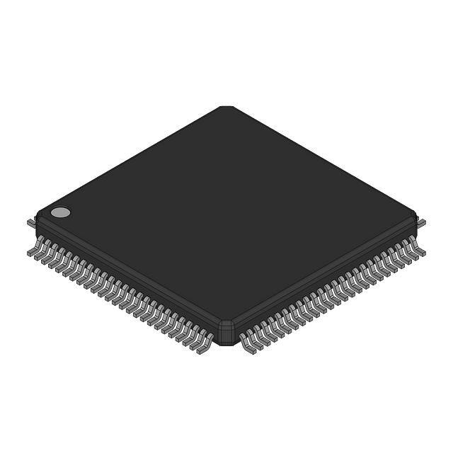


 工商网监
湘ICP备2023018690号
工商网监
湘ICP备2023018690号
