UM11077
TEA1936xDB1533 45 W USB-PD and QC 4.0 demo board
Rev. 1 — 16 April 2018
User manual
Document information
Information
Content
Keywords
TEA1936xDB1533, TEA1936x universal serial bus, power delivery, USB-PD,
quick charge QC 4.0, USB-PD 2.0, and 3.0, type-C
Abstract
This user manual describes the performance, technical data, and the
connections of the TEA1936xDB1533 demo board. The TEA1936xDB1533
demo board operates at mains voltages from 90 V (AC) up to 264 V (AC) with
an output voltage from 5 V (DC) up to 20 V (DC).
�UM11077
NXP Semiconductors
TEA1936xDB1533 45 W USB-PD and QC 4.0 demo board
Revision history
Rev
Date
Description
v.1
20180416
first issue
UM11077
User manual
All information provided in this document is subject to legal disclaimers.
Rev. 1 — 16 April 2018
© NXP B.V. 2018. All rights reserved.
2 / 22
�UM11077
NXP Semiconductors
TEA1936xDB1533 45 W USB-PD and QC 4.0 demo board
1
Introduction
Warning
The non-insulated high voltages that are present when operating this product,
constitute a risk of electric shock, personal injury, death and/or ignition of fire.
This product is intended for evaluation purposes only. It shall be operated in a
designated test area by personnel qualified according to local requirements and
labor laws to work with non-insulated mains voltages and high-voltage circuits. This
product shall never be operated unattended.
This user manual describes the operation of the TEA1936xDB1533 demo board. The
TEA1936xDB1533 features the quasi-resonant controller TEA19361, the synchronous
rectifier controller TEA1999, and the USB-PD Type-C and QC 4.0 controller TEA19032.
The TEA1936xDB1533 demo board is designed for delivering a maximum output power
of 45 W at a maximum current of 3 A. Output voltages can be chosen from 5 V up to
20 V.
The TEA1936xDB1533 provides an effective solution with a low current ripple and high
efficiency for USB-PD and quick charge applications.
-
+
VBus
TEA1999
SR CONTROLLER
TEA19361
QR CONTROLLER
USB
TYPE-C
PLUG
TEA19032
OPTO/COMMS
USB-PD TYPE-C
AND
QUICK CHARGE 4.0
CONTROLLER FOR SMPS
CC1
CC2
GND
aaa-029913
Figure 1. TEA1936xDB1533 principle schematic
UM11077
User manual
All information provided in this document is subject to legal disclaimers.
Rev. 1 — 16 April 2018
© NXP B.V. 2018. All rights reserved.
3 / 22
�UM11077
NXP Semiconductors
TEA1936xDB1533 45 W USB-PD and QC 4.0 demo board
1.1 Key features
•
•
•
•
•
•
•
•
Multi-protocol support for USB-PD 2.0 and 3.0, Quick Charge 4.0
Functionality user-configurable end of line
Best-in-class energy efficiency meeting all DOE & EU CoC requirements
< 30 mW no-load power, low audible noise, low output voltage ripple
Small size due to high near-full digital integration level and > 15.9 W/CI power density
Best-in-class Thermal management
Safe solution with extensive set of hardware-integrated protection features
Complete one-stop-shop solution from NXP Semiconductors minimizing development
time and research and development cost
1.2 Applications
Mobile chargers with Type-C connector for:
•
•
•
•
Mobile phones
Smart phones
Tablets
Notebooks
The new smart charger platform of NXP Semiconductors helps designers of travel
adapters to maximize power output for the smallest form-factor with a short bill of
materials.
The result is a cost-effective design. It meets the requirements published by Energy Star,
the Department of Energy (DoE) in the United States, the Ecodesign Directive of the
European Union, the European Code of Conduct, and other guidelines.
Supporting hardware (UTC) and software (GUI) for USB-PD available for jump-starting
application.
UM11077
User manual
All information provided in this document is subject to legal disclaimers.
Rev. 1 — 16 April 2018
© NXP B.V. 2018. All rights reserved.
4 / 22
�UM11077
NXP Semiconductors
TEA1936xDB1533 45 W USB-PD and QC 4.0 demo board
2
Safety warning
The TEA1936xDB1533 demo board is connected to the mains voltage. Avoid touching
the board while it is connected to the mains voltage and when it is in operation. An
isolated housing is obligatory when used in uncontrolled, non-laboratory environments.
Galvanic isolation from the mains phase using a fixed or variable transformer is always
recommended.
Figure 2 shows the symbols on how to recognize these devices.
019aab173
019aab174
a. Isolated
b. Not isolated
Figure 2. Isolation symbols
3
Specifications
Table 1. TEA1936xDB1533 specifications
Symbol
Parameter
Value
Vmains
AC mains voltage
90 V (AC) up to 264 V (AC)
Pout(max)
maximum output power
45 W
fmains
mains frequency
47 Hz to 63 Hz
Pidle
no-load input power
< 30 mW
η
efficiency
> 92 %; at Pout(max)
Vout
output voltage
5 V (DC) to 20 V (DC)
Iout(max)
maximum output current
3A
Vripple(burst)
output voltage ripple in burst mode
100 mV (p-p); at cable end
Vripple(full)
output voltage ripple at continuous
switching
80 mV (p-p); at cable end
EMI
conducted EMI
−7 dB
CMN
common-mode noise
< 2 V (p-p)
ESD
electrostatic discharge
±15 kV; through air
±8 kV; via contact
UM11077
User manual
All information provided in this document is subject to legal disclaimers.
Rev. 1 — 16 April 2018
© NXP B.V. 2018. All rights reserved.
5 / 22
�UM11077
NXP Semiconductors
TEA1936xDB1533 45 W USB-PD and QC 4.0 demo board
4
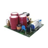
Board photographs
Figure 3. TEA1936xDB1533 demo board
a. Top view
b. Bottom view
Figure 4. TEA1936xDB1533
UM11077
User manual
All information provided in this document is subject to legal disclaimers.
Rev. 1 — 16 April 2018
© NXP B.V. 2018. All rights reserved.
6 / 22
�UM11077
NXP Semiconductors
TEA1936xDB1533 45 W USB-PD and QC 4.0 demo board
5
TEA1936xDB1533 demo board connections
The TEA1936xDB1533 demo board is a universal mains supplied application. The output
is the Type-C receptacle. Setting the output voltage is done through the USB type-C
interface. Additionally, the TEO II graphical user interface software provides the option
to program other output voltages and limit currents into the TEA19032 PD controller IC.
Section 7 lists the default settings.
Figure 5. TEA1936xDB1533 demo board connections
UM11077
User manual
All information provided in this document is subject to legal disclaimers.
Rev. 1 — 16 April 2018
© NXP B.V. 2018. All rights reserved.
7 / 22
�UM11077
NXP Semiconductors
TEA1936xDB1533 45 W USB-PD and QC 4.0 demo board
6
TEA1936xDB1533 demo board performance
6.1 Efficiency
Table 2. Efficiency at 5 V output (PCB end)
Load
Efficiency at
115 V (AC)(%)
Efficiency at
230 V (AC)(%)
10 % (0.3 A)
87.8
84.4
25 % (0.75 A)
88.6
85.7
50 % (1.5 A)
89.3
86.6
75 % (2.25 A)
90
86.9
100 % (3 A)
90.1
88.9
4-point average
89.5
87
Load
Efficiency at
115 V (AC)(%)
Efficiency at
230 V (AC)(%)
10 % (0.3 A)
88.5
86.1
25 % (0.75 A)
90.0
87.6
50 % (1.5 A)
91.2
89.0
75 % (2.25 A)
92.5
90.7
100 % (3 A)
92.4
92.1
4-point average
91.5
89.8
Load
Efficiency at
115 V (AC)(%)
Efficiency at
230 V (AC)(%)
10 % (0.3 A)
86.5
84.8
25 % (0.75 A)
88.8
87.7
50 % (1.5 A)
91.8
90.5
75 % (2.25 A)
93.2
92.0
100 % (3 A)
92.9
93.0
4-point average
91.7
90.8
Table 3. Efficiency at 9 V output (PCB end)
Table 4. Efficiency at 15 V output (PCB end)
UM11077
User manual
All information provided in this document is subject to legal disclaimers.
Rev. 1 — 16 April 2018
© NXP B.V. 2018. All rights reserved.
8 / 22
�UM11077
NXP Semiconductors
TEA1936xDB1533 45 W USB-PD and QC 4.0 demo board
Table 5. Efficiency at 20 V output (PCB end)
Load
Efficiency at
115 V (AC)(%)
Efficiency at
230 V (AC)(%)
10 % (0.23 A)
86.1
84.2
25 % (0.575 A)
88.9
87.5
50 % (1.15 A)
91.8
89.9
75 % (1.725 A)
92.8
92.3
100 % (2.3 A)
93.0
92.8
4-point average
91.6
90.6
6.2 No-load power consumption at 5 V output
Table 6. No-load power consumption
Type-C cable disconnected.
UM11077
User manual
Input voltage (V (AC))
Input frequency (Hz)
No-load power (mW)
90
60
21.1
115
60
21.6
150
60
22.2
180
50
22.3
200
50
22.9
230
50
23.9
264
50
28.4
All information provided in this document is subject to legal disclaimers.
Rev. 1 — 16 April 2018
© NXP B.V. 2018. All rights reserved.
9 / 22
�UM11077
NXP Semiconductors
TEA1936xDB1533 45 W USB-PD and QC 4.0 demo board
6.3 ElectroMagnetic Interference (EMI)
Protective earth is connected to secondary ground.
Figure 6. Conducted EMI at full load 115 V (AC)/60 Hz
Protective earth is connected to secondary ground.
Figure 7. Conducted EMI at full load 230 V (AC)/50 Hz; pass with > 5 dB margin
UM11077
User manual
All information provided in this document is subject to legal disclaimers.
Rev. 1 — 16 April 2018
© NXP B.V. 2018. All rights reserved.
10 / 22
�UM11077
NXP Semiconductors
TEA1936xDB1533 45 W USB-PD and QC 4.0 demo board
6.4 Thermal
a. Top side
b. Bottom side
Figure 8. Thermal performance; Vin = 115 V (AC); Pout = 45 W
a. Top side
b. Bottom side
Figure 9. Thermal performance; Vin = 230 V (AC); Pout = 45 W
Note: Typical temperature distribution at Tamb = 25 °C; PCB in free air, natural
convection, and radiation only. For the TEA1936xDB1533 demo board, the voltage levels
must not exceed 20 V also. Current limit levels must not exceed 3 A. Power limit levels
must not exceed 45 W.
UM11077
User manual
All information provided in this document is subject to legal disclaimers.
Rev. 1 — 16 April 2018
© NXP B.V. 2018. All rights reserved.
11 / 22
�UM11077
NXP Semiconductors
TEA1936xDB1533 45 W USB-PD and QC 4.0 demo board
7
PDO settings
Table 7 shows the settings of the output voltages and currents for the efficiency
measurement.
Table 7. PDO settings
Default values for demo board TEA1936xDB1533
PDO (#)
Vout (V)
Iout (A)
1
5
3
2
9
3
3
15
3
4
20
2.3
PDO settings can be changed by reprogramming the MTP settings of the TEA19032
via UTC using the TEO-II software (see the TEA190x Evaluation Overdrive (TEO) user
manual (Ref. 1).
Note: The PDOs must have an ascending voltage and power in order to work correctly.
So, V(PDO, i + 1) > V(PDO, i) and also P(PDO, i + 1) > P(PDO, i). Also, for the
TEA1936xDB1533 demo board, the voltage levels must not exceed 20 V. Current limit
levels must not exceed 3 A. Power limit levels must not exceed 45 W.
UM11077
User manual
All information provided in this document is subject to legal disclaimers.
Rev. 1 — 16 April 2018
© NXP B.V. 2018. All rights reserved.
12 / 22
�UM11077
NXP Semiconductors
TEA1936xDB1533 45 W USB-PD and QC 4.0 demo board
8
Schematic
The schematic of the TEA1936xDB1533 comprises the TEA19361 quasi-resonant controller, the TEA1999 synchronous rectifier controller, and the TEA19032
USB-PD/QC controller.
Vo
2 AT/250 V (AC)
CX1
47 nF
630 V
1
4
2
3
T1
RM8, 360 µH
D22
AS3PM
C29
22 µF
400 V
D23
AS3PM
N
C1
22 µF
400 V
C33
22 µF
400 V
C12
2.2 nF
630 V
VBUS
1
15
DRAIN
3
12
11
10
16
13
14
R7
100 kΩ
R13
0Ω
FB3
K5B RH 3.5 x 4.5 x 0.8
DRAIN
SRDRAIN
L
L3
120 µH FB2
BLM21PG220
D21
AS3PM
L1
2 x 1.2 mH
F1
8
5
D3
S2M
R16
100 Ω
GND_USB
Q1
IPD80R280P7
D5
R64
84.5 kΩ
GATE
VO_USB
U2
6
1
5
2
4
3
R39
1 MΩ
CAP
GND
XV
C6
C10
1 µF
25 V
TEA1999 4.7 µF
Q2
BSC060N10NS3
25 V
C30
560 µF
25 V
R62
47 Ω
C4
560 µF
25 V
R31
GND_USB
0.011 Ω
D24
AS3PM
SG1
sparkgap
6 mm
SOURCE
Q3
PSMN2R4-30MLD
C20
R5
470 pF
100 V
10 Ω
CY1
220 pF
250 V (AC)
BAS316
GND_USB
Vo
R24
84.5 kΩ
D4
S1ML
R25
120 kΩ
AUX
CTRL
R15
PROTECT
n.c.
2.2 kΩ
HV
U10
6
5
7
4
8 TEA19361 3
9
2
10
1
R17
4.7 Ω
C17
1 nF
50 V
R22
5.6 kΩ
C14
1 nF
50 V
R21
1 kΩ
DRIVER
R18
0.43 Ω
R19
0.43 Ω
D26
BAS521
1
ISENSE
R11
R55
150 Ω
R50
330 Ω
C7
120 Ω
U3A
TCLT1008
VCCL
2
GND
C3
10 µF
100 V
C36
10 µF
35 V
C15
470 nF
50 V
U3B
TCLT1008
C19
22 pF
50 V
VCC
OPTOC
VCCH
4
RT2
100 kΩ
D15
BAS321
C38
10 nF
50 V
R9
1 kΩ
OPTO
NTC
R53
178 kΩ
C5
100 nF
50 V
ISNS
VSNS
A3
A4
A5
A6
A7
A8
A9
CC2
A10
CC1
A12
A11
VO_USB
D2
PESD24VS2UT
GND_USB
1
10
2
9
3 TEA19032 8
4
7
5
6
SW
SW
GND
DISCH
DISCH
CC1/SCL
SCL
R14
CC2/SDA
SDA
10 Ω
CN1
12401548E4#2A
GND1
GND4
TX1+
RX1+
TX1-
RX1-
VBUS1
VBUS4
CC1
SBU2
D1+
D2-
D1-
D2+
SBU1
VBUS2
CC2
VBUS3
RX2-
TX2-
RX2+
TX2+
GND2
GND3
B12
R60
3.3 kΩ
R26
47 kΩ
GND_USB
B11
10 Ω R71
0Ω
R70
10 Ω
CC1
R61
10 Ω
R69
Vo
R54
24.3 kΩ
A2
4.7 µF, 25 V
R8
5.1 kΩ
3
A1
U1
CC2
1
2
3
4
SDA
GND
Vo
SCL
D25
PESD5V2S2UT
B10
B9
B8
GND_USB
B7
B6
B5
B4
B3
B2
B1
SH1 SH2 SH3 SH4
C41
10 µF
25 V
D1
PTVS24VS1UR
G1 G2 G3 G4
CGND
aaa-029915
Figure 10. TEA1936xDB1533 schematic diagram
UM11077
User manual
All information provided in this document is subject to legal disclaimers.
Rev. 1 — 16 April 2018
© NXP B.V. 2018. All rights reserved.
13 / 22
�UM11077
NXP Semiconductors
TEA1936xDB1533 45 W USB-PD and QC 4.0 demo board
Vin
C1
100 nF
35 V
IN
GND
EN
3
ADJ
4
R1
10 kΩ
n.m.
R2
3.3 kΩ
R3
3.3 kΩ
2
R4
1
3
4
SDA_IN
R6
SDA_OUT
10 Ω
SDA
3
4
0Ω
SDL_IN
R7
SDA
+3V3
GND
SCL
SCL
0Ω
R5
WP
8
7
6
SDA
2
CN3 n.m.
SMS-104-01-G-S
1
VCC
SCL
2
3.3 V
C2
2.2 µF
6.3 V
SCL
GND
OUT
5
WP
Vin
1
MIC5233-3V3
CN1
TMS-104-01-G-S-RA
SDA
U1
CN2 n.m.
22-28-4040
1
5
U2
24FC256
R8
0 Ω
4
VSS
3
A2
2
A1
A0
1
SCL_OUT
10 Ω
2
3
4
SDA
+3V3
GND
SCL
aaa-027412
n.m. = not mounted
2
Figure 11. Optional EEPROM demo board EEPROM_DB1418 with I C connections
UM11077
User manual
All information provided in this document is subject to legal disclaimers.
Rev. 1 — 16 April 2018
© NXP B.V. 2018. All rights reserved.
14 / 22
�UM11077
NXP Semiconductors
TEA1936xDB1533 45 W USB-PD and QC 4.0 demo board
9
Bill Of Materials (BOM)
Table 8. TEA1936xDB1533 bill of materials
Reference
Description and values
C1
capacitor; 22 μF; 20 %; 400 V; ALU; D13xL17mm EKM226M2GJ17RR
SAMXON
C3
capacitor; 10 µF; 20 %; 100 V; ALU; THT
100YXJ10M5X11
Rubycon
C4
capacitor; 560 μF; 20 %; 25 V; ALU; THT
A750MS567M1EAAE015
KEMET
C5
capacitor; 100 nF; 10 %; 50 V; X7R; 0402
C1005X7R1H104K050BB
TDK
C6
capacitor; 4.7 μF; 10 %; 25 V; X5R; 0603
C1608X5R1E475K080AC
TDK
C7
capacitor; 4.7 μF; 10 %; 16 V; X5R; 0603
C1608X5R1C475K080AC
TDK
C10
capacitor; 1 μF; 10 %; 25 V; X7R; 0603
-
-
C12
capacitor; 2200 pF; 10 %; 630 V; X7R; 1206
C1206C222KBRAC
KEMET
C14
capacitor; 1 nF; 10 %; 50 V; X7R; 0603
-
-
C15
capacitor; 470 nF; 10 %; 50 V; X7R; 0603
C1608X7R1H474K
TDK
C17
capacitor; 1 nF; 10 %; 50 V; X7R; 0603
-
-
C19
capacitor; 22 pF; 5 %; 50 V; C0G; 0603
-
-
C20
capacitor; 470 pF; 10 %; 100 V; X7R; 0603
-
-
C29
capacitor; 22 μF; 20 %; 400 V; ALU; D13xL17mm EKM226M2GJ17RR
SAMXON
C30
capacitor; 560 μF; 20 %; 25 V; ALU; THT
KEMET
C33
capacitor; 22 μF; 20 %; 400 V; ALU; D13xL17mm EKM226M2GJ17RR
SAMXON
C36
capacitor; 10 µF; 20 %; 35 V; ALU; THT
UVR1V100MDD6TP
Nichicon
C38
capacitor; 10 nF; 10 %; 50 V; X7R; 0402
-
-
C41
capacitor; 10 μF; 10 %; 25 V; X5R; 0603
C1608X5R1E106M080
TDK
CN1
Connector; USB 3.1 Type-C receptacle R/A
12401548E4#2A
Amphenol
CY1
capacitor; 220 pF; 10 %; 250 V (AC); B; THT; X1/ DE2B3KY221KA2BM01F
Y2
Murata
D1
diode; TVS; unidirectional; 24 V; 400 W
PTVS24VS1UR
NeXPeria USA Inc
D2
diode; ESD protection; 24 V; 3 A
PESD24VS2UT
NeXPeria USA Inc
D3
diode; 1 kV; 2 A
S2M
Fairchild
D4
diode; 1 kV; 1 A
S1ML
Taiwan Semiconductor
D5
diode; 100 V; 250 mA
BAS316
NeXPeria USA Inc
D15
diode; 200 V; 250 mA
BAS321
NeXPeria USA Inc
D21; D22;
D23; D24
diode; 1 kV; 3 A
AS3PM-M3/86A
Vishay
D25
diode; ESD protection; 30 kV; 3 A
PESD5V2S2UT
NXP Semiconductors
D26
diode; 300 V; 250 mA
BAS521
NeXPeria USA Inc
F1
fuse; slow blow; 250 V; 2 A
MCPMP2A250V
Multicomp
FB2
ferrite bead; 0.009 Ω; 6 A; 0805
BLM21PG220SH1D
Murata
FB3
ferrite bead; K5B RH 3.5 × 4.5 × 0.8
K5B RH 3.5 x 4.5 x 0.8 - T52
King Core Electronics
Inc.
UM11077
User manual
Part Number
A750MS567M1EAAE015
All information provided in this document is subject to legal disclaimers.
Rev. 1 — 16 April 2018
Manufacturer
© NXP B.V. 2018. All rights reserved.
15 / 22
�UM11077
NXP Semiconductors
TEA1936xDB1533 45 W USB-PD and QC 4.0 demo board
Reference
Description and values
Part Number
Manufacturer
L1
inductor CM; 2 ×1.2 mH; Cu = 0.27 mm; 18T:18T
T8x4x4 H5C3
TDK
L3
inductor; 120 μH; 850 mA; 0.22 Ω
744772121
Würth Elektronik
Q1
MOSFET-N; 800 V; 0.28 Ω; 17 A
IPD80R280P7ATMA1
Infineon
Q2
MOSFET-N; 100 V; 90 A; 0.006 Ω; TDSON
BSC060N10NS3GATMA1
Infineon
Q3
MOSFET-N; 30 V; 2.4 mΩ; 70 A
PSMN2R4-30MLD
NeXPeria USA Inc
R5
resistor; 10 Ω; 1 %; 63 mW; 0603
-
-
R7
resistor; 100 kΩ; 1 %; 660 mW; 1206
ERJP08F1003V
Panasonic
R8
resistor; 5.1 kΩ; 1 %; 63 mW; 0402
-
-
R9
resistor; 1 kΩ; 1 %; 63 mW; 0402
-
-
R11
resistor; 330 Ω; 1 %; 63 mW; 0402
-
-
R13
resistor; jumper; 0 Ω; 250 mW; 1206
-
-
R14; R61
resistor; 10 Ω; 1 %; 100 mW; 0402
ERJ2RKF10R0X
Panasonic
R15
resistor; 2.2 kΩ; 1 %; 63 mW; 0603
-
-
R16
resistor; 100 Ω; 1 %; 100 mW; 0603
-
-
R17
resistor; 4.7 Ω; 1 %; 100 mW; 0603
-
-
R18; R19
resistor; 0.43 Ω; 1 %; 250 mW; 0805
ERJS6QFR43V
Panasonic
R21
resistor; 1 kΩ; 1 %; 63 mW; 0603
-
-
R22
resistor; 5.6 kΩ; 1 %; 63 mW; 0603
-
-
R24
resistor; 84.5 kΩ; 1 %; 660 mW; 500 V; 1206
ERJP08F8452V
Panasonic
R25
resistor; 120 kΩ; 1 %; 250 mW; 250 V; 0603
ERJPA3F1203V
Panasonic
R26
resistor; NTC; 47 kΩ; 5 %; 180 mW; 3980 K
B57321V2473J060
EPCOS
R31
resistor; 0.011 Ω; 1 %; 1 W; 1206
ERJ8CWFR011V
Panasonic
R39
resistor; 1 MΩ; 1 %; 63 mW; 0402
CRCW04021M00FKED
Vishay
R50
resistor; 120 Ω; 1 %; 100 mW; 0402
ERJ2RKF1200X
Panasonic
R53
resistor; 178 kΩ; 1 %; 63 mW; 0402
-
-
R54
resistor; 24.3 kΩ; 1 %; 63 mW; 0402
-
-
R55
resistor; 150 Ω; 1 %; 100 mW; 0402
ERJ2RKF1500X
Panasonic
R60
resistor; 3.3 kΩ; 1 %; 63 mW; 0402
-
-
R62
resistor; 47 Ω; 1 %; 500 mW; 0805
ERJP6WF47R0V
Panasonic
R64
resistor; 84.5 kΩ; 1 %; 660 mW; 500 V; 1206
ERJP08F8452V
Panasonic
R69; R70
resistor; 10 Ω; 1 %; 100 mW; 0402
ERJ2RKF10R0X
Panasonic
R71
resistor; jumper; 0 Ω; 100 mW; 0402
ERJP6WF47R0V
Panasonic
RT2
resistor; NTC; 100 kΩ; 5 %; 100 mW; 4190 K
NTCLE100E3104JB0
Vishay
T1
Transformer; RM8; 360 µH
RM8 (TR1083)
NXP Semiconductors
U1
USB-PD controller
TEA19032 (SO10)
NXP Semiconductors
U2
synchronous rectification controller
TEA1999
NXP Semiconductors
U10
SMPS controller
TEA19361
NXP Semiconductors
UM11077
User manual
All information provided in this document is subject to legal disclaimers.
Rev. 1 — 16 April 2018
© NXP B.V. 2018. All rights reserved.
16 / 22
�UM11077
NXP Semiconductors
TEA1936xDB1533 45 W USB-PD and QC 4.0 demo board
Reference
Description and values
Part Number
Manufacturer
U3
optocoupler; NPN; 70 V; 50 mA
TCLT1008
Vishay
Table 9. EEPROM_DB1418 bill of materials
Reference
Description and values
Part Number
Manufacturer
C1
capacitor; 100 nF; 10 %; 35 V; X7R; 0402
-
-
C2
capacitor; 2.2 μF; 20 %; 6.3 V; X5R; 0402
GRM155R60J225ME15D
Murata
CN1
header; right angle; 1 × 4-way; 1.27 mm
TMS-104-01-G-S-RA
SAMTEC
CN2
header; not mounted; straight; 1 × 4-way;
2.54 mm
22-28-4040
Molex
CN3
receptacle; not mounted; straight; 1 × 4-way;
1.27 mm
SMS-104-01-G-S
SAMTEC
R1
resistor; not mounted; 10 kΩ; 1 %; 63 mW; 0402
CRCW040210K0FKED
Vishay
R2
resistor; 3.3 kΩ; 1 %; 63 mW; 0402
CRCW04023K30FKED
Vishay
R3
resistor; 3.3 kΩ; 1 %; 63 mW; 0402
CRCW04023K30FKED
Vishay
R4
resistor; 10 Ω; 1 %; 200 mW; 0402
ERJ-PA2F10R0X
Panasonic
R5
resistor; 10 Ω; 1 %; 200 mW; 0402
ERJ-PA2F10R0X
Panasonic
R6; R7; R8
resistor; jumper; 0 Ω; 63 mW; 0402
CRCW04020000Z0ED
Vishay
U1
LDO; 3.3 V
MIC5233-3.3YM5 TR
MICREL
24FC256-I/SN
Microchip
U2
UM11077
User manual
2
EEPROM; 256 kb; I C; CMOS
All information provided in this document is subject to legal disclaimers.
Rev. 1 — 16 April 2018
© NXP B.V. 2018. All rights reserved.
17 / 22
�UM11077
NXP Semiconductors
TEA1936xDB1533 45 W USB-PD and QC 4.0 demo board
10 Layout
a. Top view layout and assembly
b. Bottom view layout and assembly
Figure 12. TEA1936xDB1533 demo board layout
UM11077
User manual
All information provided in this document is subject to legal disclaimers.
Rev. 1 — 16 April 2018
© NXP B.V. 2018. All rights reserved.
18 / 22
�UM11077
NXP Semiconductors
TEA1936xDB1533 45 W USB-PD and QC 4.0 demo board
a. Top view and assembly
b. Bottom view and assembly
Figure 13. EEPROM_DB1418 demo board layout
UM11077
User manual
All information provided in this document is subject to legal disclaimers.
Rev. 1 — 16 April 2018
© NXP B.V. 2018. All rights reserved.
19 / 22
�UM11077
NXP Semiconductors
TEA1936xDB1533 45 W USB-PD and QC 4.0 demo board
11 Abbreviations
Table 10. Abbreviations
Acronym
Description
USB
Universal Serial Bus
PD
Power Delivery
QC
Quick Charge
UTC
Universal Type-C Controller
PDO
Power Data Object
MTP
Multiple Times Programmable
TEO
TEA190x Evaluation Overdrive
12 References
1
UM11077
User manual
UM11014 user manual
TEA190x Evaluation Overdrive (TEO); 2017, NXP
Semiconductors
All information provided in this document is subject to legal disclaimers.
Rev. 1 — 16 April 2018
© NXP B.V. 2018. All rights reserved.
20 / 22
�UM11077
NXP Semiconductors
TEA1936xDB1533 45 W USB-PD and QC 4.0 demo board
13 Legal information
13.1 Definitions
Draft — The document is a draft version only. The content is still under
internal review and subject to formal approval, which may result in
modifications or additions. NXP Semiconductors does not give any
representations or warranties as to the accuracy or completeness of
information included herein and shall have no liability for the consequences
of use of such information.
13.2 Disclaimers
Limited warranty and liability — Information in this document is believed
to be accurate and reliable. However, NXP Semiconductors does not
give any representations or warranties, expressed or implied, as to the
accuracy or completeness of such information and shall have no liability
for the consequences of use of such information. NXP Semiconductors
takes no responsibility for the content in this document if provided by an
information source outside of NXP Semiconductors. In no event shall NXP
Semiconductors be liable for any indirect, incidental, punitive, special or
consequential damages (including - without limitation - lost profits, lost
savings, business interruption, costs related to the removal or replacement
of any products or rework charges) whether or not such damages are based
on tort (including negligence), warranty, breach of contract or any other
legal theory. Notwithstanding any damages that customer might incur for
any reason whatsoever, NXP Semiconductors’ aggregate and cumulative
liability towards customer for the products described herein shall be limited
in accordance with the Terms and conditions of commercial sale of NXP
Semiconductors.
Right to make changes — NXP Semiconductors reserves the right to
make changes to information published in this document, including without
limitation specifications and product descriptions, at any time and without
notice. This document supersedes and replaces all information supplied prior
to the publication hereof.
Suitability for use — NXP Semiconductors products are not designed,
authorized or warranted to be suitable for use in life support, life-critical or
safety-critical systems or equipment, nor in applications where failure or
malfunction of an NXP Semiconductors product can reasonably be expected
to result in personal injury, death or severe property or environmental
damage. NXP Semiconductors and its suppliers accept no liability for
inclusion and/or use of NXP Semiconductors products in such equipment or
applications and therefore such inclusion and/or use is at the customer’s own
risk.
Applications — Applications that are described herein for any of these
products are for illustrative purposes only. NXP Semiconductors makes
no representation or warranty that such applications will be suitable
for the specified use without further testing or modification. Customers
are responsible for the design and operation of their applications and
products using NXP Semiconductors products, and NXP Semiconductors
accepts no liability for any assistance with applications or customer product
UM11077
User manual
design. It is customer’s sole responsibility to determine whether the NXP
Semiconductors product is suitable and fit for the customer’s applications
and products planned, as well as for the planned application and use of
customer’s third party customer(s). Customers should provide appropriate
design and operating safeguards to minimize the risks associated with
their applications and products. NXP Semiconductors does not accept any
liability related to any default, damage, costs or problem which is based
on any weakness or default in the customer’s applications or products, or
the application or use by customer’s third party customer(s). Customer is
responsible for doing all necessary testing for the customer’s applications
and products using NXP Semiconductors products in order to avoid a
default of the applications and the products or of the application or use by
customer’s third party customer(s). NXP does not accept any liability in this
respect.
Export control — This document as well as the item(s) described herein
may be subject to export control regulations. Export might require a prior
authorization from competent authorities.
Evaluation products — This product is provided on an “as is” and “with all
faults” basis for evaluation purposes only. NXP Semiconductors, its affiliates
and their suppliers expressly disclaim all warranties, whether express,
implied or statutory, including but not limited to the implied warranties of
non-infringement, merchantability and fitness for a particular purpose. The
entire risk as to the quality, or arising out of the use or performance, of this
product remains with customer. In no event shall NXP Semiconductors, its
affiliates or their suppliers be liable to customer for any special, indirect,
consequential, punitive or incidental damages (including without limitation
damages for loss of business, business interruption, loss of use, loss of
data or information, and the like) arising out the use of or inability to use
the product, whether or not based on tort (including negligence), strict
liability, breach of contract, breach of warranty or any other theory, even if
advised of the possibility of such damages. Notwithstanding any damages
that customer might incur for any reason whatsoever (including without
limitation, all damages referenced above and all direct or general damages),
the entire liability of NXP Semiconductors, its affiliates and their suppliers
and customer’s exclusive remedy for all of the foregoing shall be limited to
actual damages incurred by customer based on reasonable reliance up to
the greater of the amount actually paid by customer for the product or five
dollars (US$5.00). The foregoing limitations, exclusions and disclaimers
shall apply to the maximum extent permitted by applicable law, even if any
remedy fails of its essential purpose.
Translations — A non-English (translated) version of a document is for
reference only. The English version shall prevail in case of any discrepancy
between the translated and English versions.
13.3 Trademarks
Notice: All referenced brands, product names, service names and
trademarks are the property of their respective owners.
GreenChip — is a trademark of NXP B.V.
All information provided in this document is subject to legal disclaimers.
Rev. 1 — 16 April 2018
© NXP B.V. 2018. All rights reserved.
21 / 22
�UM11077
NXP Semiconductors
TEA1936xDB1533 45 W USB-PD and QC 4.0 demo board
Contents
1
1.1
1.2
2
3
4
5
6
6.1
6.2
6.3
6.4
7
8
9
10
11
12
13
Introduction ......................................................... 3
Key features ...................................................... 4
Applications ........................................................4
Safety warning .................................................... 5
Specifications ...................................................... 5
Board photographs .............................................6
TEA1936xDB1533 demo board connections .... 7
TEA1936xDB1533
demo
board
performance .........................................................8
Efficiency ............................................................8
No-load power consumption at 5 V output .........9
ElectroMagnetic Interference (EMI) ................. 10
Thermal ............................................................11
PDO settings ..................................................... 12
Schematic .......................................................... 13
Bill Of Materials (BOM) .....................................15
Layout .................................................................18
Abbreviations .................................................... 20
References ......................................................... 20
Legal information .............................................. 21
Please be aware that important notices concerning this document and the product(s)
described herein, have been included in section 'Legal information'.
© NXP B.V. 2018.
All rights reserved.
For more information, please visit: http://www.nxp.com
For sales office addresses, please send an email to: salesaddresses@nxp.com
Date of release: 16 April 2018
Document identifier: UM11077
�