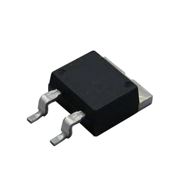
TDH50 Series
50 watt D2-PAK TO-263 Thick Film Surface Mount
F e at u r e s
• 50W high power resistors in TO263 (D2-PAK) style
package with matte Tin plated flange.
• Non-inductive design suits high frequency applications and high-speed pulse circuits.
• Low, 2.3 deg C/W heat resistance from resistor hot
spot to flange and long life performance are presented with thick film metallization technology.
• Wide, 20 mΩ to 51K Ω resistance range.
A p p l i c at i o n s
• Automotive
• Measurements
• Industrial computers
• High frequency electronics
• UPS
• Power unit of machines
• Motor control
• Drive circuits
characteristics
Test Condition
Value
Rating Power -55°C to 25°C flange temperature
(when used with proper heatsink cooling system)
Attached on simple footprint
2 Watt
Heat Resistance Resistor hot spot to flange
2.3°C/W
Resistance Range Resistance at terminal foot portion
Nominal Res. Include 2.5, 4.0, 5.0, 8.0 and 16
TCR TCR (ppm/°C) of low resistance will
typically be increased as indicated.
Testing point is at 5.27mm from
bottom of molding of terminals
50 Watt
300ppm
200ppm
140ppm
80ppm
0.02Ω
0.05Ω
0.1Ω
0.2Ω
Tolerance 1% tolerance at 0.01-0.091Ω are available
0.02-
0.091Ω
0.1-
9.1Ω
1051KΩ
E6
E24
E24
250
100
50
5%(J)
1% (F)
5% (J)
±1% (F)
Capacitance Equivalent parallel capacitance
1.44pF
Inductance Equivalent series inductance
8.38nH
Operation Temp.
Operating Volt. P is rating power and R resistance
Withstand. Volt. Terminal and flange, 60 seconds. 1mA
-55°C to +155°C
Either 500V or √P·R
2000 VAC
Load Life 25°C, 90 min.ON, 30 min. OFF, 1000h.
±1.0%
Humidity 40°C, 90-95%RH, DC 0.1W, 1000 hours.
±1.0%
Temp. Cycle -55°C,30 min., +155°C,30 min., 5cyc
Soldering Heat 350±5°C, 3 sec.,
Lead Solderability 245±5°C, 3seconds.
Insulation Between terminals and tab.
Resistance
Vibration IEC60068-2-6. Test method is IEC60068-2-6, and
specification is sine sweep wave form, 100Hz-2000Hz, 10 cycles, amplitude
0.75mm or 100m/s2, 90minutes. direction x-y z, Amplitude 0.75mm will be
applied under break point Frequency (about 60Hz) and 100m/ s2 over break
point
Flammability
Weight
±0.25%
±0.1%
Over 95% of surface
Over 1,000MΩ
±0.25%
UL94-V0
1.5 grams
(continued)
38
1-866-9-OHMITE • Int’l 1-847-258-0300 • Fax 1-847-574-7522 • www.ohmite.com • info@ohmite.com
�TDH50 Series
50 watt D2-PAK TO-263 Thick Film Surface Mount
characteristics
Pulse Energy Durability
10K
1K
100
500W
100
10
120
Tentative continuous-pulse power allowance
at duty 0.01. Load life test will be necessary in
actual equipment, because curve will be
changed by resistance, repetition, duty and
operating temerature.
% Rated Power
Pulse peak power (W)
100K
Derating
50W
10n 100n 1u 100u 1m 100m 1
Pulse width (seconds)
10 1000
60
40
20
155°
0
-50° -25° 0° 25° 50° 75° 100° 125° 150° 175°
Terminal Temp. (°C)
Soldering
Peak temp. time 20-40sec.
Construction
Exceed 217 C permissible
time 60 sec. to 180 sec.
Molding, epoxy, UL94-V0
Leads, Tin plated Cu
Leads joint, 85%Pb-Sn solder
Resistor, Ni-Cr or RuO
Substrate, Alumina
Joint, 85%Pb-Sn solder
Flange, matte tin plated Cu
Temperature °C
350
Resistor element is
electrically insulated
from the metal flange
80
300
Peak temp.
270°C
240°C
From 150°C to 200°C,
120 sec. to 180 sec.
250
200
Pre-heat temp.
200°C
150°C
150
100
50
0
To maximum temp. 400 sec.
0
50 100 150 200 250 300 350 400 450 500 550 600
Time (s)
dimensions
1.5 ±0.05
10.1 ±0.2
10.3 ±0.2
2.2 ±0.2
2.5 ±0.5
5.0 ±1.0
0.75 ±0.05
1.5 ±0.05
5.08 ±0.10
Land
Pattern
2.75 ±0.2
12.7
Tape Dimensions
Tape and Reel packaging supplied in 500 pcs per reel.
5.0 ±.2
0.4 ±.1
16.0 ±.1
2.0 ±.1
11.5 ±.1
0.5 ±0.05
1.75 ±.1
4.5 ±0.2
24.0 ±.3
15.8 ±.1
10.16
10.8 ±.1
9.65
(4.75)
5.08
4.0 ±.1
4.32
1.27
Reel Dimensions
Outer diameter: 330mm Width: 23.9mm min. 27.4mm max
Inner diameter: 100mm Package quantity: 500pcs/13” reel
(continued)
1-866-9-OHMITE • Int’l 1-847-258-0300 • Fax 1-847-574-7522 • www.ohmite.com • info@ohmite.com
39
�TDH50 Series
50 watt D2-PAK TO-263 Thick Film Surface Mount
o r d e r i n g i n f o r m at i o n
TDH50HR100JE-TR
Style
Tape and reel
(optional)
500 per reel
50 pcs tubes
standard
Modifier Ohms
Tolerance RoHS Compliant
Non-compliant
R = Decimal F = 1%
version unavailable
Example:
J = 5%
R100 = 0.10
1R00= 1.0
10K0= 10,000
Standard Ohm Values
Ohms
0.05
0.1
0.2
1
2
5
10
20
25
50
75
100
200
500
1,000
10,000
Part Number
Tolerance
TDH50HR050JE
5%
TDH50H10R0FE
TDH50H20R0FE
TDH50H25R0FE
TDH50H50R0FE
TDH50H75R0FE
1%
1%
1%
1%
1%
TDH50HR100FE
TDH50HR200FE
TDH50H1R00FE
TDH50H2R00FE
TDH50H5R00FE
TDH50H100RFE
TDH50H200RFE
TDH50H500RFE
TDH50H1K00FE
TDH50H10K0FE
THIS PRODUCT IS DESIGNED FOR
USE WITH PROPER HEATSINKING.
Maximum base plate temperature of the resistor must
be monitored and kept within specified limits to establish the power rating. Best technique is to attach a
thermocouple to the side of the base plate of the resistor. Temperature of plastic housing or heat sink cannot
be used to establish rating of the resistor.
rev 11/20-1
40
1-866-9-OHMITE • Int’l 1-847-258-0300 • Fax 1-847-574-7522 • www.ohmite.com • info@ohmite.com
1%
1%
1%
1%
1%
1%
1%
1%
1%
1%
�
很抱歉,暂时无法提供与“TDH50HR200FE-TR”相匹配的价格&库存,您可以联系我们找货
免费人工找货