A22N
Pushbutton Switches/Selector Switches/Indicators
Pushbutton Switches
New Product
A22N/M22N/A30N
A30N
A30N
Selector Switches
A30N
Key-type Selector Switches
Page 35
Pushbutton Switches
A30NN/A30NL
A30NN-P/A30NL-P
Page 53
Selector Switches
A30NS/A30NW
A30NS-P/A30NW-P
Page 64
Key-type Selector Switches
A30NK
A30NK-P
Page 74
Safety
Precautions
Page 47
Accessories
and Tools
Indicators
M22N
M22N-P
Subassemblies
(Common)
Screw terminal block type
Push-In Plus terminal block type
Pushbutton Switches
Page 20
30 dia.
A30N Series
M22N
Key-type Selector Switches
A22NK
A22NK-P
Indicators
Screw terminal block type
Push-In Plus terminal block type
A22N
A22N/M22N Series
Selector Switches
A22NS/A22NW
A22NS-P/A22NW-P
Key-type Selector Switches
22 dia.
Page 2
A22N
Pushbutton Switches
A22NN/A22NL
A22NN-P/A22NL-P
Selector Switches
Control panel miniaturization through a more compact design and
modified wiring direction
Addition of Push-In Plus terminal blocks for easy wiring
Workability and safety improvements
1
�Pushbutton Switches
A22N
Pushbutton Switches
A22N
Selector Switches
A22N
Key-type Selector Switches
M22N
Indicators
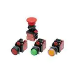
A22NN/A22NL
22-mm dia. Pushbutton Switches
Control panel miniaturization through a more
compact design and modified wiring direction.
Addition of Push-In Plus terminal blocks for easy
wiring.
Pushbutton Switches
A30N
A30N
Selector Switches
A30N
Key-type Selector Switches
Easy to Use
Safety
• Improved wiring visibility through to a modified wiring
direction. (Push-In Plus terminal block type)
• Screw terminal block structure is compatible with
round crimp terminals. (Screw terminal block type)
• The terminals can be secured even when a contact
block is mounted. (Screw terminal block type)
• Contact Blocks can be attached in any direction for
easy assembly.
• Easy-to-operate lock lever for secure locking.
• Easy-mounting Contact Blocks provide finger protection.
• No loose connections of wiring means maintenance-free
use. (Push-In Plus terminal block type)
Miniaturization
• No need for extra lateral space because of the
modified wiring direction.
(Push-In Plus terminal block type)
• Compact design.
• A22NL (lighted models) are the same size as A22NN
(non-lighted models).
Subassemblies
(Common)
• Meet global safety standards.
• Can be installed in two types of panel hole
dimensions: 22.3 and 25.5 dia.
• The buttons and bezels come in a wide variety of
colors, shapes, and materials.
• Standard-feature degree of protection: IP66, NEMA
4X, and NEMA 13.
Refer to Safety Precautions for All Pushbutton Switches/
Indicators and Safety Precautions on page 88.
Button Colors
Safety
Precautions
Red
Green
Yellow
White
Blue
Black
Red
Green
Yellow
White
Blue
Orange
Red
Green
Yellow
White
Blue
Orange
White
Red
Green
Yellow
White
Blue
Orange
Opaque
white*
A22NN-
-N
Opaque
Non-lighted
Switches
A22NN-
-U
Transparent
Accessories
and Tools
2
Product Lineup
When
not lit
Lighted
Switches
A22NL-
-T
Transparent
When lit
* The colors when the Switches are lit are for transparent white buttons (code: TW) and yellow LED Lamps (code: Y).
�A22N
List of Models
Pushbutton Switches
A22NN/A22NL
Screw Terminal Blocks/Push-In Plus Terminal Blocks
Plastic bezels
Brushed metal bezels
A30N
Pushbutton Switches
A30N
Selector Switches
A30N
Key-type Selector Switches
Projected
A22N-MG
Full guard
A22N-BM
Mushroom
M22N
Full guard
Indicators
A22N-BG
A22N-RP
A22N
A22N-MP
Projected
Key-type Selector Switches
A22N-BP
Projected
A22N-RN
Flat
A22N
A22N-MN
Flat
Selector Switches
A22N-BN
Flat
Metal bezels
A22N-MM
Mushroom
A22N-RM
Mushroom
Subassemblies
(Common)
Accessories
and Tools
Safety
Precautions
3
�A22N
Pushbutton Switches
A22NN/A22NL
Model Number Structure
Model Number Legend - - - - - -Shipped as a set that includes the Operation Unit, LED Lamp (lighted models only), Mounting
Collar, Contact Block, and Lighting Unit (lighted models only).
For information on combinations, refer to Ordering Information on pages 5 to 8.
Selector Switches
A22N
Model Numbers for Sets
(1)
(3)
(4)
(5)
(6)
(7)
(8) (9)
A22N L - BN M - TR A - G 100 - R B
A22N
Key-type Selector Switches
(1) Type
(5) Degree of Protection
Code
Description
Code
Description
N
Non-lighted
A
Conforming to IP66, NEMA 4X, NEMA13
L
Lighted
(6) Contacts and Terminals Specifications
(2) Bezel Material and Button Shape
Code
Indicators
M22N
Pushbutton Switches
A30N
Selector Switches
A30N
Key-type Selector Switches
A30N
Subassemblies
(Common)
Accessories
and Tools
Safety
Precautions
4
(2)
Bezel material
Code
Specification
Button shape
G
General/Screw terminal block
P
General/Push-In Plus Terminal Block
BN
Plastic
Flat
BP
Plastic
Projected
(7) Contacts
BG
Plastic
Full guard
BM
Plastic
Mushroom
MN
Brushed metal
Flat
MP
Brushed metal
Projected
MG
Brushed metal
Full guard
MM
Brushed metal
Mushroom
RN
Metal
Flat
002
0
1
---
RP
Metal
Projected
101
2
0
NO
RM
Metal
Mushroom
102
1
1
NO
202
0
2
NC
111
3
0
NO NO NO
112
2
1
NO NO NC
122
1
2
NO NC NC
222
0
3
NC NC NC
Code
100
(3) Switch Action
Code
Description
M
Momentary
A
Alternate
(4) Button Transparency and Color and (8) LED Lamp Color
Lighted/non-lighted
Non-lighted
Lighted
Code (4) Code (8) Transparency
Button color
NR
N
Opaque
Red
NG
N
Opaque
Green
NY
N
Opaque
Yellow
NW
N
Opaque
White
NA
N
Opaque
Blue
NB
N
Opaque
Black
UR
N
Transparent
Red
UG
N
Transparent
Green
UY
N
Transparent
Yellow
UW
N
Transparent
White
LED lamp
color
Contact
Blocks
Unit position
Non-lighted
Lighted
NO
NC
1
2
3
1
2
3
1
0
NO
---
---
NO
Lighting Unit
---
---
NC
---
Lighting Unit
NC
---
NO NO
Lighting Unit
NO
---
NC NO
Lighting Unit
NC
---
NC NC
Lighting Unit
NC
Note: 1. NO (blue): Normally open, NC (orange):
Normally closed.
2. Refer to the following figure for Unit positions.
---
(9) LED Lamp Voltage
UA
N
Transparent
Blue
Code
LED Lamp voltage
UO
N
Transparent
Orange
N
Non-lighted
TR
R
Transparent
Red
Red
A
6 VAC/DC
TG
G
Transparent
Green
Green
B
12 VAC/DC
TY
Y
Transparent
Yellow
Yellow
C
24 VAC/DC
TW
W
Transparent
White
White
D
100/110/120 VAC
E
200/220/230/240 VAC
TA
A
Transparent
Blue
Blue
TO
O
Transparent
Orange
Orange
TW
Y
Transparent
White *
Yellow
* The color is opaque white when the Switch is lit.
■ Specifications: Refer to page 13.
■ Dimensions: Refer to pages 15 to 17.
■ Precautions for correct use: Refer to pages 88 to 99.
■ Accessories and tools: Refer to pages 84 to 85.
�Model Numbers for Sets - - - - Shipped as a set that includes the Operation Unit, LED Lamp (lighted models only), Mounting
A22N
Ordering Information
Pushbutton Switches
A22NN/A22NL
Collar, Contact Block, and Lighting Unit (lighted models only).
A22NN-BNM-(4)(4)A-G(7)(7)(7)-NN
A22NN-BNA-(4)(4)A-G(7)(7)(7)-NN
A22NN-BNM-(4)(4)A-P(7)(7)(7)-NN
A22NN-BNA-(4)(4)A-P(7)(7)(7)-NN
A22NN-MNM-(4)(4)A-G(7)(7)(7)-NN
A22NN-MNA-(4)(4)A-G(7)(7)(7)-NN
A22NN-MNM-(4)(4)A-P(7)(7)(7)-NN
A22NN-MNA-(4)(4)A-P(7)(7)(7)-NN
A22NN-MNM-(4)(4)A-G(7)(7)(7)-NN
A22NN-MNA-(4)(4)A-G(7)(7)(7)-NN
A22NN-MNM-(4)(4)A-P(7)(7)(7)-NN
A22NN-MNA-(4)(4)A-P(7)(7)(7)-NN
A22NN-MNM-(4)(4)A-G(7)(7)(7)-NN
A22NN-MNA-(4)(4)A-G(7)(7)(7)-NN
A22NN-MNM-(4)(4)A-P(7)(7)(7)-NN
A22NN-MNA-(4)(4)A-P(7)(7)(7)-NN
101
102
202
3
Brushed metal
bezels
1
2
3
Metal bezels
1
2
A22NN-RNM-(4)(4)A-G(7)(7)(7)-NN
A22NN-RNA-(4)(4)A-G(7)(7)(7)-NN
A22NN-RNM-(4)(4)A-P(7)(7)(7)-NN
A22NN-RNA-(4)(4)A-P(7)(7)(7)-NN
A22NN-RNM-(4)(4)A-G(7)(7)(7)-NN
A22NN-RNA-(4)(4)A-G(7)(7)(7)-NN
A22NN-RNM-(4)(4)A-P(7)(7)(7)-NN
A22NN-RNA-(4)(4)A-P(7)(7)(7)-NN
A22NN-RNM-(4)(4)A-G(7)(7)(7)-NN
A22NN-RNA-(4)(4)A-G(7)(7)(7)-NN
A22NN-RNM-(4)(4)A-P(7)(7)(7)-NN
A22NN-RNA-(4)(4)A-P(7)(7)(7)-NN
NR: Opaque, red
NG: Opaque, green
NY: Opaque, yellow
NW:Opaque, white
NA: Opaque, blue
NB: Opaque, black
UR: Transparent, red
UG: Transparent, green
UY: Transparent, yellow
UW:Transparent, white
UA: Transparent, blue
UO: Transparent, orange
111
112
122
222
100
002
101
102
202
111
112
122
222
100
002
101
102
202
111
112
122
222
3
Lighted, Flat Switches
Appearance
Contacts
Momentary action
(self-resetting)
Alternate action
(self-holding)
Model
Plastic bezels
1
2
1
2
Metal bezels
2
A22NL-BNA(4)(4)A-G(7)(7)(7)-(8)(9)
A22NL-BNM(4)(4)A-P(7)(7)(7)-(8)(9)
A22NL-BNA(4)(4)A-P(7)(7)(7)-(8)(9)
A22NL-BNM(4)(4)A-G(7)(7)(7)-(8)(9)
A22NL-BNA(4)(4)A-G(7)(7)(7)-(8)(9)
A22NL-BNM(4)(4)A-P(7)(7)(7)-(8)(9)
A22NL-BNA(4)(4)A-P(7)(7)(7)-(8)(9)
A22NL-MNM(4)(4)A-G(7)(7)(7)-(8)(9)
A22NL-MNA(4)(4)A-G(7)(7)(7)-(8)(9)
A22NL-MNM(4)(4)A-P(7)(7)(7)-(8)(9)
A22NL-MNA(4)(4)A-P(7)(7)(7)-(8)(9)
A22NL-MNM(4)(4)A-G(7)(7)(7)-(8)(9)
A22NL-MNA(4)(4)A-G(7)(7)(7)-(8)(9)
A22NL-MNM(4)(4)A-P(7)(7)(7)-(8)(9)
A22NL-MNA(4)(4)A-P(7)(7)(7)-(8)(9)
A22NL-RNM(4)(4)A-G(7)(7)(7)-(8)(9)
A22NL-RNA(4)(4)A-G(7)(7)(7)-(8)(9)
A22NL-RNM(4)(4)A-P(7)(7)(7)-(8)(9)
A22NL-RNA(4)(4)A-P(7)(7)(7)-(8)(9)
A22NL-RNM(4)(4)A-G(7)(7)(7)-(8)(9)
A22NL-RNA(4)(4)A-G(7)(7)(7)-(8)(9)
A22NL-RNM(4)(4)A-P(7)(7)(7)-(8)(9)
A22NL-RNA(4)(4)A-P(7)(7)(7)-(8)(9)
(8)
LED Lamp
color
100
002
101
102
202
TR: Transparent, red
TG: Transparent, green
TY: Transparent, yellow
TW: Transparent, white
TA: Transparent, blue
TO:Transparent, orange
100
002
101
102
202
R: Red
G: Green
Y: Yellow
W: White
A: Blue
O: Orange
100
002
101
102
202
■ Specifications: Refer to page 13.
■ Dimensions: Refer to pages 15 to 17.
■ Accessories and tools: Refer to pages 84 to 85.
A:
B:
C:
D:
E:
6 VAC/DC
12 VAC/DC
24 VAC/DC
100/110/120 VAC
200/220/230/240 VAC
Safety
Precautions
Note: Normally, the Button and LED Lamp with the same color are combined.
However, opaque white is available by combining a white Button and yellow LED. A22N--TWA--Y
■ Subassemblies: Refer to pages 9 to 12 and 82.
(You can order Operation Units, LED Lamps, Mounting Collars, and
Contact Blocks individually.)
(9)
LED Lamp voltage
Accessories
and Tools
1
Model
A22NL-BNM(4)(4)A-G(7)(7)(7)-(8)(9)
(7)(7)(7)
Contacts
Subassemblies
(Common)
Brushed metal
bezels
(4)(4)
Button color
A30N
A22NN-BNA-(4)(4)A-P(7)(7)(7)-NN
Key-type Selector Switches
A22NN-BNM-(4)(4)A-P(7)(7)(7)-NN
A30N
A22NN-BNA-(4)(4)A-G(7)(7)(7)-NN
Selector Switches
A22NN-BNM-(4)(4)A-G(7)(7)(7)-NN
100
002
A30N
A22NN-BNA-(4)(4)A-G(7)(7)(7)-NN
A22NN-BNA-(4)(4)A-P(7)(7)(7)-NN
(7)(7)(7)
Contacts
Pushbutton Switches
A22NN-BNM-(4)(4)A-G(7)(7)(7)-NN
A22NN-BNM-(4)(4)A-P(7)(7)(7)-NN
(4)(4)
Button color
M22N
Model
Indicators
2
Alternate action (self-holding)
Model
A22N
1
Momentary action (self-resetting)
Key-type Selector Switches
Plastic bezels
Contacts
A22N
Appearance
Selector Switches
Non-lighted, Flat Switches
5
�A22N
Pushbutton Switches
A22NN/A22NL
Ordering Information
Model Numbers for Sets - - - - Shipped as a set that includes the Operation Unit, LED Lamp (lighted models only), Mounting
Collar, Contact Block, and Lighting Unit (lighted models only).
A22N
Selector Switches
Non-lighted, Projected Switches
Appearance
Plastic bezels
Contacts
1
A22N
Key-type Selector Switches
2
Alternate action (self-holding)
Model
Model
Brushed metal
bezels
Indicators
M22N
A22NN-BPM-(4)(4)A-G(7)(7)(7)-NN
A22NN-BPA-(4)(4)A-G(7)(7)(7)-NN
A22NN-BPM-(4)(4)A-P(7)(7)(7)-NN
A22NN-BPA-(4)(4)A-P(7)(7)(7)-NN
A22NN-BPM-(4)(4)A-G(7)(7)(7)-NN
A22NN-BPA-(4)(4)A-G(7)(7)(7)-NN
A22NN-BPM-(4)(4)A-P(7)(7)(7)-NN
A22NN-BPA-(4)(4)A-P(7)(7)(7)-NN
A22NN-BPM-(4)(4)A-G(7)(7)(7)-NN
A22NN-BPA-(4)(4)A-G(7)(7)(7)-NN
A22NN-BPM-(4)(4)A-P(7)(7)(7)-NN
A22NN-BPA-(4)(4)A-P(7)(7)(7)-NN
A22NN-MPM-(4)(4)A-G(7)(7)(7)-NN
A22NN-MPA-(4)(4)A-G(7)(7)(7)-NN
A22NN-MPM-(4)(4)A-P(7)(7)(7)-NN
A22NN-MPA-(4)(4)A-P(7)(7)(7)-NN
A22NN-MPM-(4)(4)A-G(7)(7)(7)-NN
A22NN-MPA-(4)(4)A-G(7)(7)(7)-NN
A22NN-MPM-(4)(4)A-P(7)(7)(7)-NN
A22NN-MPA-(4)(4)A-P(7)(7)(7)-NN
A22NN-MPM-(4)(4)A-G(7)(7)(7)-NN
A22NN-MPA-(4)(4)A-G(7)(7)(7)-NN
A22NN-MPM-(4)(4)A-P(7)(7)(7)-NN
A22NN-MPA-(4)(4)A-P(7)(7)(7)-NN
(4)(4)
Button color
(7)(7)(7)
Contacts
100
002
101
102
202
3
1
2
3
Metal bezels
Pushbutton Switches
A30N
Selector Switches
A30N
Key-type Selector Switches
A30N
Subassemblies
(Common)
Accessories
and Tools
Safety
Precautions
6
Momentary action (self-resetting)
1
2
A22NN-RPM-(4)(4)A-G(7)(7)(7)-NN
A22NN-RPA-(4)(4)A-G(7)(7)(7)-NN
A22NN-RPM-(4)(4)A-P(7)(7)(7)-NN
A22NN-RPA-(4)(4)A-P(7)(7)(7)-NN
A22NN-RPM-(4)(4)A-G(7)(7)(7)-NN
A22NN-RPA-(4)(4)A-G(7)(7)(7)-NN
A22NN-RPM-(4)(4)A-P(7)(7)(7)-NN
A22NN-RPA-(4)(4)A-P(7)(7)(7)-NN
A22NN-RPM-(4)(4)A-G(7)(7)(7)-NN
A22NN-RPA-(4)(4)A-G(7)(7)(7)-NN
A22NN-RPM-(4)(4)A-P(7)(7)(7)-NN
A22NN-RPA-(4)(4)A-P(7)(7)(7)-NN
NR: Opaque, red
NG: Opaque, green
NY: Opaque, yellow
NW:Opaque, white
NA: Opaque, blue
NB: Opaque, black
UR: Transparent, red
UG: Transparent, green
UY: Transparent, yellow
UW:Transparent, white
UA: Transparent, blue
UO: Transparent, orange
111
112
122
222
100
002
101
102
202
111
112
122
222
100
002
101
102
202
111
112
122
222
3
Lighted, Projected Switches
Appearance
Contacts
Momentary action
(self-resetting)
Alternate action
(self-holding)
Model
Plastic bezels
1
2
Brushed metal
bezels
1
2
Metal bezels
1
2
(4)(4)
Button color
Model
A22NL-BPM(4)(4)A-G(7)(7)(7)-(8)(9)
A22NL-BPA(4)(4)A-G(7)(7)(7)-(8)(9)
A22NL-BPM(4)(4)A-P(7)(7)(7)-(8)(9)
A22NL-BPA(4)(4)A-P(7)(7)(7)-(8)(9)
A22NL-BPM(4)(4)A-G(7)(7)(7)-(8)(9)
A22NL-BPA(4)(4)A-G(7)(7)(7)-(8)(9)
A22NL-BPM(4)(4)A-P(7)(7)(7)-(8)(9)
A22NL-BPA(4)(4)A-P(7)(7)(7)-(8)(9)
A22NL-MPM(4)(4)A-G(7)(7)(7)-(8)(9)
A22NL-MPA(4)(4)A-G(7)(7)(7)-(8)(9)
A22NL-MPM(4)(4)A-P(7)(7)(7)-(8)(9)
A22NL-MPA(4)(4)A-P(7)(7)(7)-(8)(9)
A22NL-MPM(4)(4)A-G(7)(7)(7)-(8)(9)
A22NL-MPA(4)(4)A-G(7)(7)(7)-(8)(9)
A22NL-MPM(4)(4)A-P(7)(7)(7)-(8)(9)
A22NL-MPA(4)(4)A-P(7)(7)(7)-(8)(9)
A22NL-RPM(4)(4)A-G(7)(7)(7)-(8)(9)
A22NL-RPA(4)(4)A-G(7)(7)(7)-(8)(9)
A22NL-RPM(4)(4)A-P(7)(7)(7)-(8)(9)
A22NL-RPA(4)(4)A-P(7)(7)(7)-(8)(9)
A22NL-RPM(4)(4)A-G(7)(7)(7)-(8)(9)
A22NL-RPA(4)(4)A-G(7)(7)(7)-(8)(9)
A22NL-RPM(4)(4)A-P(7)(7)(7)-(8)(9)
A22NL-RPA(4)(4)A-P(7)(7)(7)-(8)(9)
(7)(7)(7)
Contacts
(8)
LED Lamp
color
100
002
101
102
202
TR: Transparent, red
TG: Transparent, green
TY: Transparent, yellow
TW: Transparent, white
TA: Transparent, blue
TO: Transparent, orange
100
002
101
102
202
R: Red
G: Green
Y: Yellow
W: White
A: Blue
O: Orange
100
002
101
102
202
Note: Normally, the Button and LED Lamp with the same color are combined.
However, opaque white is available by combining a white Button and yellow LED. A22N--TWA--Y
■ Subassemblies: Refer to pages 9 to 12 and 82.
(You can order Operation Units, LED Lamps, Mounting Collars, and
Contact Blocks individually.)
(9)
LED Lamp voltage
■ Specifications: Refer to page 13.
■ Dimensions: Refer to pages 15 to 17.
■ Accessories and tools: Refer to pages 84 to 85.
A:
B:
C:
D:
E:
6 VAC/DC
12 VAC/DC
24 VAC/DC
100/110/120 VAC
200/220/230/240 VAC
�Model Numbers for Sets - - - - Shipped as a set that includes the Operation Unit, LED Lamp (lighted models only), Mounting
A22N
Ordering Information
Pushbutton Switches
A22NN/A22NL
Collar, Contact Block, and Lighting Unit (lighted models only).
A22NN-BGA-(4)(4)A-P(7)(7)(7)-NN
A22NN-BGM-(4)(4)A-G(7)(7)(7)-NN
A22NN-BGA-(4)(4)A-G(7)(7)(7)-NN
A22NN-BGM-(4)(4)A-P(7)(7)(7)-NN
A22NN-BGA-(4)(4)A-P(7)(7)(7)-NN
A22NN-MGM-(4)(4)A-G(7)(7)(7)-NN
A22NN-MGA-(4)(4)A-G(7)(7)(7)-NN
A22NN-MGM-(4)(4)A-P(7)(7)(7)-NN
A22NN-MGA-(4)(4)A-P(7)(7)(7)-NN
A22NN-MGM-(4)(4)A-G(7)(7)(7)-NN
A22NN-MGA-(4)(4)A-G(7)(7)(7)-NN
A22NN-MGM-(4)(4)A-P(7)(7)(7)-NN
A22NN-MGA-(4)(4)A-P(7)(7)(7)-NN
A22NN-MGM-(4)(4)A-G(7)(7)(7)-NN
A22NN-MGA-(4)(4)A-G(7)(7)(7)-NN
A22NN-MGM-(4)(4)A-P(7)(7)(7)-NN
A22NN-MGA-(4)(4)A-P(7)(7)(7)-NN
3
Brushed metal
bezels
1
2
NR: Opaque, red
NG: Opaque, green
NY: Opaque, yellow
NW:Opaque, white
NA: Opaque, blue
NB: Opaque, black
UR: Transparent, red
UG: Transparent, green
UY: Transparent, yellow
UW:Transparent, white
UA: Transparent, blue
UO: Transparent, orange
101
102
202
111
112
122
222
100
002
101
102
202
111
112
122
222
3
A30N
A22NN-BGM-(4)(4)A-P(7)(7)(7)-NN
Key-type Selector Switches
A22NN-BGA-(4)(4)A-G(7)(7)(7)-NN
A30N
A22NN-BGM-(4)(4)A-G(7)(7)(7)-NN
100
002
Selector Switches
A22NN-BGA-(4)(4)A-P(7)(7)(7)-NN
A30N
A22NN-BGA-(4)(4)A-G(7)(7)(7)-NN
(7)(7)(7)
Contacts
Pushbutton Switches
A22NN-BGM-(4)(4)A-G(7)(7)(7)-NN
A22NN-BGM-(4)(4)A-P(7)(7)(7)-NN
(4)(4)
Button color
M22N
Model
Indicators
2
Alternate action (self-holding)
Model
A22N
1
Momentary action (self-resetting)
Key-type Selector Switches
Plastic bezels
Contacts
A22N
Appearance
Selector Switches
Non-lighted, Full-guard Switches
Lighted, Full-guard Switches
Appearance
Plastic bezels
Contacts
1
2
Brushed metal
bezels
1
2
Momentary action
(self-resetting)
Alternate action
(self-holding)
Model
Model
(4)(4)
Button color
A22NL-BGM(4)(4)A-G(7)(7)(7)-(8)(9)
A22NL-BGA(4)(4)A-G(7)(7)(7)-(8)(9)
A22NL-BGM(4)(4)A-P(7)(7)(7)-(8)(9)
A22NL-BGA(4)(4)A-P(7)(7)(7)-(8)(9)
A22NL-BGM(4)(4)A-G(7)(7)(7)-(8)(9)
A22NL-BGA(4)(4)A-G(7)(7)(7)-(8)(9)
A22NL-BGM(4)(4)A-P(7)(7)(7)-(8)(9)
A22NL-BGA(4)(4)A-P(7)(7)(7)-(8)(9)
A22NL-MGM(4)(4)A-G(7)(7)(7)-(8)(9)
A22NL-MGA(4)(4)A-G(7)(7)(7)-(8)(9)
A22NL-MGM(4)(4)A-P(7)(7)(7)-(8)(9)
A22NL-MGA(4)(4)A-P(7)(7)(7)-(8)(9)
A22NL-MGM(4)(4)A-G(7)(7)(7)-(8)(9)
A22NL-MGA(4)(4)A-G(7)(7)(7)-(8)(9)
A22NL-MGM(4)(4)A-P(7)(7)(7)-(8)(9)
A22NL-MGA(4)(4)A-P(7)(7)(7)-(8)(9)
(7)(7)(7)
Contacts
(8)
LED Lamp
color
(9)
LED Lamp voltage
100
002
TR: Transparent, red
TG: Transparent, green
TY: Transparent, yellow
TW: Transparent, white
TA: Transparent, blue
TO: Transparent, orange
101
102
202
100
002
R: Red
G: Green
Y: Yellow
W: White
A: Blue
O: Orange
101
102
202
A:
B:
C:
D:
E:
6 VAC/DC
12 VAC/DC
24 VAC/DC
100/110/120 VAC
200/220/230/240 VAC
Note: Normally, the Button and LED Lamp with the same color are combined.
However, opaque white is available by combining a white Button and yellow LED. A22N--TWA--Y
Subassemblies
(Common)
Accessories
and Tools
■ Specifications: Refer to page 13.
■ Dimensions: Refer to pages 15 to 17.
■ Accessories and tools: Refer to pages 84 to 85.
Safety
Precautions
■ Subassemblies: Refer to pages 9 to 12 and 82.
(You can order Operation Units, LED Lamps, Mounting Collars, and
Contact Blocks individually.)
7
�A22N
Pushbutton Switches
A22NN/A22NL
Ordering Information
Model Numbers for Sets - - - - Shipped as a set that includes the Operation Unit, LED Lamp (lighted models only), Mounting
Collar, Contact Block, and Lighting Unit (lighted models only).
A22N
Selector Switches
Non-lighted, Mushroom Switches
Appearance
Plastic bezels
Contacts
1
A22N
Key-type Selector Switches
2
Alternate action (self-holding)
Model
Model
Brushed metal
bezels
Indicators
M22N
A22NN-BMA-(4)(4)A-G(7)(7)(7)-NN
A22NN-BMA-(4)(4)A-P(7)(7)(7)-NN
A22NN-BMM-(4)(4)A-G(7)(7)(7)-NN
A22NN-BMA-(4)(4)A-G(7)(7)(7)-NN
A22NN-BMM-(4)(4)A-P(7)(7)(7)-NN
A22NN-BMA-(4)(4)A-P(7)(7)(7)-NN
A22NN-BMM-(4)(4)A-G(7)(7)(7)-NN
A22NN-BMA-(4)(4)A-G(7)(7)(7)-NN
A22NN-BMM-(4)(4)A-P(7)(7)(7)-NN
A22NN-BMA-(4)(4)A-P(7)(7)(7)-NN
1
A22NN-MMM-(4)(4)A-G(7)(7)(7)-NN
A22NN-MMA-(4)(4)A-G(7)(7)(7)-NN
A22NN-MMM-(4)(4)A-P(7)(7)(7)-NN
A22NN-MMA-(4)(4)A-P(7)(7)(7)-NN
A22NN-MMM-(4)(4)A-G(7)(7)(7)-NN
A22NN-MMA-(4)(4)A-G(7)(7)(7)-NN
A22NN-MMM-(4)(4)A-P(7)(7)(7)-NN
A22NN-MMA-(4)(4)A-P(7)(7)(7)-NN
A22NN-MMM-(4)(4)A-G(7)(7)(7)-NN
A22NN-MMA-(4)(4)A-G(7)(7)(7)-NN
A22NN-MMM-(4)(4)A-P(7)(7)(7)-NN
A22NN-MMA-(4)(4)A-P(7)(7)(7)-NN
A22NN-RMM-(4)(4)A-G(7)(7)(7)-NN
A22NN-RMA-(4)(4)A-G(7)(7)(7)-NN
A22NN-RMM-(4)(4)A-P(7)(7)(7)-NN
A22NN-RMA-(4)(4)A-P(7)(7)(7)-NN
A22NN-RMM-(4)(4)A-G(7)(7)(7)-NN
A22NN-RMA-(4)(4)A-G(7)(7)(7)-NN
A22NN-RMM-(4)(4)A-P(7)(7)(7)-NN
A22NN-RMA-(4)(4)A-P(7)(7)(7)-NN
A22NN-RMM-(4)(4)A-G(7)(7)(7)-NN
A22NN-RMA-(4)(4)A-G(7)(7)(7)-NN
A22NN-RMM-(4)(4)A-P(7)(7)(7)-NN
A22NN-RMA-(4)(4)A-P(7)(7)(7)-NN
3
Metal bezels
Pushbutton Switches
A30N
A22NN-BMM-(4)(4)A-G(7)(7)(7)-NN
A22NN-BMM-(4)(4)A-P(7)(7)(7)-NN
(4)(4)
Button color
(7)(7)(7)
Contacts
100
002
101
102
202
3
2
1
2
NR: Opaque, red
NG: Opaque, green
NY: Opaque, yellow
NW:Opaque, white
NA: Opaque, blue
NB: Opaque, black
UR: Transparent, red
UG: Transparent, green
UY: Transparent, yellow
UW:Transparent, white
UA: Transparent, blue
UO: Transparent, orange
111
112
122
222
100
002
101
102
202
111
112
122
222
100
002
101
102
202
111
112
122
222
3
A30N
Selector Switches
Lighted, Mushroom Switches
Appearance
Contacts
Plastic bezels
A30N
Key-type Selector Switches
1
2
Brushed metal
bezels
Subassemblies
(Common)
1
2
Metal bezels
1
Accessories
and Tools
Safety
Precautions
8
Momentary action (self-resetting)
2
Momentary action
(self-resetting)
Alternate action
(self-holding)
Model
Model
(4)(4)
Button color
A22NL-BMM(4)(4)A-G(7)(7)(7)-(8)(9)
A22NL-BMA(4)(4)A-G(7)(7)(7)-(8)(9)
A22NL-BMM(4)(4)A-P(7)(7)(7)-(8)(9)
A22NL-BMA(4)(4)A-P(7)(7)(7)-(8)(9)
A22NL-BMM(4)(4)A-G(7)(7)(7)-(8)(9)
A22NL-BMA(4)(4)A-G(7)(7)(7)-(8)(9)
A22NL-BMM(4)(4)A-P(7)(7)(7)-(8)(9)
A22NL-BMA(4)(4)A-P(7)(7)(7)-(8)(9)
A22NL-MMM(4)(4)A-G(7)(7)(7)-(8)(9)
A22NL-MMA(4)(4)A-G(7)(7)(7)-(8)(9)
A22NL-MMM(4)(4)A-P(7)(7)(7)-(8)(9)
A22NL-MMA(4)(4)A-P(7)(7)(7)-(8)(9)
A22NL-MMM(4)(4)A-G(7)(7)(7)-(8)(9)
A22NL-MMA(4)(4)A-G(7)(7)(7)-(8)(9)
A22NL-MMM(4)(4)A-P(7)(7)(7)-(8)(9)
A22NL-MMA(4)(4)A-P(7)(7)(7)-(8)(9)
A22NL-RMM(4)(4)A-G(7)(7)(7)-(8)(9)
A22NL-RMA(4)(4)A-G(7)(7)(7)-(8)(9)
A22NL-RMM(4)(4)A-P(7)(7)(7)-(8)(9)
A22NL-RMA(4)(4)A-P(7)(7)(7)-(8)(9)
A22NL-RMM(4)(4)A-G(7)(7)(7)-(8)(9)
A22NL-RMA(4)(4)A-G(7)(7)(7)-(8)(9)
A22NL-RMM(4)(4)A-P(7)(7)(7)-(8)(9)
A22NL-RMA(4)(4)A-P(7)(7)(7)-(8)(9)
(7)(7)(7)
Contacts
(8)
LED Lamp
color
100
002
101
102
202
TR: Transparent, red
TG: Transparent, green
TY: Transparent, yellow
TW: Transparent, white
TA: Transparent, blue
TO: Transparent, orange
100
002
101
102
202
R: Red
G: Green
Y: Yellow
W: White
A: Blue
O: Orange
100
002
101
102
202
Note: Normally, the Button and LED Lamp with the same color are combined.
However, opaque white is available by combining a white Button and yellow LED. A22N--TWA--Y
■ Subassemblies: Refer to pages 9 to 12 and 82.
(You can order Operation Units, LED Lamps, Mounting Collars, and
Contact Blocks individually.)
(9)
LED Lamp voltage
■ Specifications: Refer to page 13.
■ Dimensions: Refer to pages 15 to 17.
■ Accessories and tools: Refer to pages 84 to 85.
A:
B:
C:
D:
E:
6 VAC/DC
12 VAC/DC
24 VAC/DC
100/110/120 VAC
200/220/230/240 VAC
�Switch Structure - - - -
You can order Operation Units, LED Lamps (lighted models only), Mounting Collars, Contact Blocks, and
Lighting Units (lighted models only) separately. Use them in combination for models that are not available as
assembled Switches. They can also be used as inventory for maintenance parts.
A22N
Key-type Selector Switches
M22N
Indicators
A30N
Pushbutton Switches
A30N
Selector Switches
A30N
Key-type Selector Switches
Metal Operation Units
A22N
Brushed Metal Operation Units
Selector Switches
Plastic Operation Units
A22N
Ordering Information
Pushbutton Switches
A22NN/A22NL
Mounting Collar
Non-lighted models
Lighted models
LED Lamp
Contact Blocks
Screw terminal block type
Contact Blocks
Push-In Plus terminal block type
Contact Blocks
+ Lighting Unit
Screw terminal block type
Contact Blocks
+ Lighting Unit
Push-In Plus terminal block type
Subassemblies
(Common)
Accessories
and Tools
■ Specifications: Refer to page 13.
■ Dimensions: Refer to pages 15 to 17.
■ Accessories and tools: Refer to pages 84 to 85.
Safety
Precautions
■ Model numbers of sets: Refer to pages 5 to 8.
■ Subassemblies (Common): Refer to page 82.
9
�A22N
Pushbutton Switches
A22NN/A22NL
Ordering Information
Subassemblies - - - - - You can order Operation Units, LED Lamps (lighted models only), Mounting Collars, Contact Blocks, and
Lighting Units (lighted models only) separately. Use them in combination for models that are not available as
assembled Switches. They can also be used as inventory for maintenance parts.
A22N
Selector Switches
Operation Units
Plastic, flat
Key-type Selector Switches
A22N
Indicators
M22N
Pushbutton Switches
A30N
Bezel material and button shape
Switch Action
Lighted/
non-lighted
Non-lighted
Lighted
Selector Switches
A30N
Key-type Selector Switches
A30N
Subassemblies
(Common)
Accessories
and Tools
Safety
Precautions
10
Plastic, projected
Transparency
Momentary
Alternate
Momentary
Alternate
Model
Model
Model
Model
Color
Opaque
Red
A22NZ-BNM-NRA
A22NZ-BNA-NRA
A22NZ-BPM-NRA
Opaque
Green
A22NZ-BNM-NGA
A22NZ-BNA-NGA
A22NZ-BPM-NGA
A22NZ-BPA-NGA
Opaque
Yellow
A22NZ-BNM-NYA
A22NZ-BNA-NYA
A22NZ-BPM-NYA
A22NZ-BPA-NYA
Opaque
White
A22NZ-BNM-NWA
A22NZ-BNA-NWA
A22NZ-BPM-NWA
A22NZ-BPA-NWA
Opaque
Blue
A22NZ-BNM-NAA
A22NZ-BNA-NAA
A22NZ-BPM-NAA
A22NZ-BPA-NAA
Opaque
Black
A22NZ-BNM-NBA
A22NZ-BNA-NBA
A22NZ-BPM-NBA
A22NZ-BPA-NBA
Red
A22NZ-BNM-URA
A22NZ-BNA-URA
A22NZ-BPM-URA
A22NZ-BPA-URA
Transparent
A22NZ-BPA-NRA
Transparent
Green
A22NZ-BNM-UGA
A22NZ-BNA-UGA
A22NZ-BPM-UGA
A22NZ-BPA-UGA
Transparent
Yellow
A22NZ-BNM-UYA
A22NZ-BNA-UYA
A22NZ-BPM-UYA
A22NZ-BPA-UYA
Transparent
White
A22NZ-BNM-UWA
A22NZ-BNA-UWA
A22NZ-BPM-UWA
A22NZ-BPA-UWA
Transparent
Blue
A22NZ-BNM-UAA
A22NZ-BNA-UAA
A22NZ-BPM-UAA
A22NZ-BPA-UAA
Transparent
Orange
A22NZ-BNM-UOA
A22NZ-BNA-UOA
A22NZ-BPM-UOA
A22NZ-BPA-UOA
Transparent
Red
A22NZ-BNM-TRA
A22NZ-BNA-TRA
A22NZ-BPM-TRA
A22NZ-BPA-TRA
Transparent
Green
A22NZ-BNM-TGA
A22NZ-BNA-TGA
A22NZ-BPM-TGA
A22NZ-BPA-TGA
Transparent
Yellow
A22NZ-BNM-TYA
A22NZ-BNA-TYA
A22NZ-BPM-TYA
A22NZ-BPA-TYA
Transparent
White
A22NZ-BNM-TWA
A22NZ-BNA-TWA
A22NZ-BPM-TWA
A22NZ-BPA-TWA
Transparent
Blue
A22NZ-BNM-TAA
A22NZ-BNA-TAA
A22NZ-BPM-TAA
A22NZ-BPA-TAA
Transparent
Orange
A22NZ-BNM-TOA
A22NZ-BNA-TOA
A22NZ-BPM-TOA
A22NZ-BPA-TOA
Plastic, full-guard
Plastic, mushroom
Bezel material and button shape
Switch Action
Lighted/
non-lighted
Non-lighted
Lighted
Transparency
Momentary
Alternate
Momentary
Alternate
Model
Model
Model
Model
Color
Opaque
Red
A22NZ-BGM-NRA
A22NZ-BGA-NRA
A22NZ-BMM-NRA
Opaque
Green
A22NZ-BGM-NGA
A22NZ-BGA-NGA
A22NZ-BMM-NGA
A22NZ-BMA-NGA
Opaque
Yellow
A22NZ-BGM-NYA
A22NZ-BGA-NYA
A22NZ-BMM-NYA
A22NZ-BMA-NYA
Opaque
White
A22NZ-BGM-NWA
A22NZ-BGA-NWA
A22NZ-BMM-NWA
A22NZ-BMA-NWA
Opaque
Blue
A22NZ-BGM-NAA
A22NZ-BGA-NAA
A22NZ-BMM-NAA
A22NZ-BMA-NAA
Opaque
Black
A22NZ-BGM-NBA
A22NZ-BGA-NBA
A22NZ-BMM-NBA
A22NZ-BMA-NBA
Red
A22NZ-BGM-URA
A22NZ-BGA-URA
A22NZ-BMM-URA
A22NZ-BMA-URA
Transparent
Green
A22NZ-BGM-UGA
A22NZ-BGA-UGA
A22NZ-BMM-UGA
A22NZ-BMA-UGA
Transparent
Yellow
A22NZ-BGM-UYA
A22NZ-BGA-UYA
A22NZ-BMM-UYA
A22NZ-BMA-UYA
Transparent
White
A22NZ-BGM-UWA
A22NZ-BGA-UWA
A22NZ-BMM-UWA
A22NZ-BMA-UWA
Transparent
Blue
A22NZ-BGM-UAA
A22NZ-BGA-UAA
A22NZ-BMM-UAA
A22NZ-BMA-UAA
Transparent
Orange
A22NZ-BGM-UOA
A22NZ-BGA-UOA
A22NZ-BMM-UOA
A22NZ-BMA-UOA
Transparent
Red
A22NZ-BGM-TRA
A22NZ-BGA-TRA
A22NZ-BMM-TRA
A22NZ-BMA-TRA
Transparent
Green
A22NZ-BGM-TGA
A22NZ-BGA-TGA
A22NZ-BMM-TGA
A22NZ-BMA-TGA
Transparent
Yellow
A22NZ-BGM-TYA
A22NZ-BGA-TYA
A22NZ-BMM-TYA
A22NZ-BMA-TYA
Transparent
White
A22NZ-BGM-TWA
A22NZ-BGA-TWA
A22NZ-BMM-TWA
A22NZ-BMA-TWA
Transparent
Blue
A22NZ-BGM-TAA
A22NZ-BGA-TAA
A22NZ-BMM-TAA
A22NZ-BMA-TAA
Transparent
Orange
A22NZ-BGM-TOA
A22NZ-BGA-TOA
A22NZ-BMM-TOA
A22NZ-BMA-TOA
Transparent
■ Model numbers of sets: Refer to pages 5 to 8.
■ Subassemblies (Common): Refer to page 82.
A22NZ-BMA-NRA
■ Specifications: Refer to page 13.
■ Dimensions: Refer to pages 15 to 17.
■ Accessories and tools: Refer to pages 84 to 85.
�Subassemblies
- - - - -You can order Operation Units, LED Lamps (lighted models only), Mounting Collars, Contact Blocks, and
A22N
Ordering Information
Pushbutton Switches
A22NN/A22NL
Lighting Units (lighted models only) separately. Use them in combination for models that are not available as
assembled Switches. They can also be used as inventory for maintenance parts.
A22NZ-MNM-NGA
Yellow
A22NZ-MNM-NYA
Opaque
White
A22NZ-MNM-NWA
Alternate
Model
Model
A22NZ-MPM-NRA
A22NZ-MPA-NRA
A22NZ-MNA-NGA
A22NZ-MPM-NGA
A22NZ-MPA-NGA
A22NZ-MNA-NYA
A22NZ-MPM-NYA
A22NZ-MPA-NYA
A22NZ-MNA-NWA
A22NZ-MPM-NWA
A22NZ-MPA-NWA
Opaque
Blue
A22NZ-MNM-NAA
A22NZ-MNA-NAA
A22NZ-MPM-NAA
A22NZ-MPA-NAA
Opaque
Black
A22NZ-MNM-NBA
A22NZ-MNA-NBA
A22NZ-MPM-NBA
A22NZ-MPA-NBA
Transparent
Red
A22NZ-MNM-URA
A22NZ-MNA-URA
A22NZ-MPM-URA
A22NZ-MPA-URA
Transparent
Green
A22NZ-MNM-UGA
A22NZ-MNA-UGA
A22NZ-MPM-UGA
A22NZ-MPA-UGA
Transparent
Yellow
A22NZ-MNM-UYA
A22NZ-MNA-UYA
A22NZ-MPM-UYA
A22NZ-MPA-UYA
Transparent
White
A22NZ-MNM-UWA
A22NZ-MNA-UWA
A22NZ-MPM-UWA
A22NZ-MPA-UWA
Transparent
Blue
A22NZ-MNM-UAA
A22NZ-MNA-UAA
A22NZ-MPM-UAA
A22NZ-MPA-UAA
Transparent
Orange
A22NZ-MNM-UOA
A22NZ-MNA-UOA
A22NZ-MPM-UOA
A22NZ-MPA-UOA
Transparent
Red
A22NZ-MNM-TRA
A22NZ-MNA-TRA
A22NZ-MPM-TRA
A22NZ-MPA-TRA
Transparent
Green
A22NZ-MNM-TGA
A22NZ-MNA-TGA
A22NZ-MPM-TGA
A22NZ-MPA-TGA
Transparent
Yellow
A22NZ-MNM-TYA
A22NZ-MNA-TYA
A22NZ-MPM-TYA
A22NZ-MPA-TYA
Transparent
White
A22NZ-MNM-TWA
A22NZ-MNA-TWA
A22NZ-MPM-TWA
A22NZ-MPA-TWA
Transparent
Blue
A22NZ-MNM-TAA
A22NZ-MNA-TAA
A22NZ-MPM-TAA
A22NZ-MPA-TAA
Transparent
Orange
A22NZ-MNM-TOA
A22NZ-MNA-TOA
A22NZ-MPM-TOA
A22NZ-MPA-TOA
Brushed metal, full-guard
A30N
Green
Opaque
Key-type Selector Switches
Opaque
A30N
A22NZ-MNA-NRA
Selector Switches
Model
A22NZ-MNM-NRA
A30N
Lighted
Model
Red
Pushbutton Switches
Non-lighted
Color
Momentary
M22N
Opaque
Alternate
Indicators
Transparency
Momentary
A22N
Switch Action
Lighted/
non-lighted
Key-type Selector Switches
Bezel material and button shape
A22N
Brushed metal, projected
Selector Switches
Brushed metal, flat
Brushed metal, mushroom
Bezel material and button shape
Switch Action
Lighted/
non-lighted
Momentary
Alternate
Model
Model
Model
Model
Color
Opaque
Red
A22NZ-MGM-NRA
A22NZ-MGA-NRA
A22NZ-MMM-NRA
A22NZ-MMA-NRA
Opaque
Green
A22NZ-MGM-NGA
A22NZ-MGA-NGA
A22NZ-MMM-NGA
A22NZ-MMA-NGA
Opaque
Yellow
A22NZ-MGM-NYA
A22NZ-MGA-NYA
A22NZ-MMM-NYA
A22NZ-MMA-NYA
Opaque
White
A22NZ-MGM-NWA
A22NZ-MGA-NWA
A22NZ-MMM-NWA
A22NZ-MMA-NWA
Opaque
Blue
A22NZ-MGM-NAA
A22NZ-MGA-NAA
A22NZ-MMM-NAA
A22NZ-MMA-NAA
Opaque
Black
A22NZ-MGM-NBA
A22NZ-MGA-NBA
A22NZ-MMM-NBA
A22NZ-MMA-NBA
Transparent
Red
A22NZ-MGM-URA
A22NZ-MGA-URA
A22NZ-MMM-URA
A22NZ-MMA-URA
Transparent
Green
A22NZ-MGM-UGA
A22NZ-MGA-UGA
A22NZ-MMM-UGA
A22NZ-MMA-UGA
Transparent
Yellow
A22NZ-MGM-UYA
A22NZ-MGA-UYA
A22NZ-MMM-UYA
A22NZ-MMA-UYA
Transparent
White
A22NZ-MGM-UWA
A22NZ-MGA-UWA
A22NZ-MMM-UWA
A22NZ-MMA-UWA
Transparent
Blue
A22NZ-MGM-UAA
A22NZ-MGA-UAA
A22NZ-MMM-UAA
A22NZ-MMA-UAA
Transparent
Orange
A22NZ-MGM-UOA
A22NZ-MGA-UOA
A22NZ-MMM-UOA
A22NZ-MMA-UOA
Transparent
Red
A22NZ-MGM-TRA
A22NZ-MGA-TRA
A22NZ-MMM-TRA
A22NZ-MMA-TRA
Green
A22NZ-MGM-TGA
A22NZ-MGA-TGA
A22NZ-MMM-TGA
A22NZ-MMA-TGA
Transparent
Yellow
A22NZ-MGM-TYA
A22NZ-MGA-TYA
A22NZ-MMM-TYA
A22NZ-MMA-TYA
Transparent
White
A22NZ-MGM-TWA
A22NZ-MGA-TWA
A22NZ-MMM-TWA
A22NZ-MMA-TWA
Transparent
Blue
A22NZ-MGM-TAA
A22NZ-MGA-TAA
A22NZ-MMM-TAA
A22NZ-MMA-TAA
Transparent
Orange
A22NZ-MGM-TOA
A22NZ-MGA-TOA
A22NZ-MMM-TOA
A22NZ-MMA-TOA
■ Model numbers of sets: Refer to pages 5 to 8.
■ Subassemblies (Common): Refer to page 82.
■ Specifications: Refer to page 13.
■ Dimensions: Refer to pages 15 to 17.
■ Accessories and tools: Refer to pages 84 to 85.
Safety
Precautions
Transparent
Accessories
and Tools
Lighted
Alternate
Subassemblies
(Common)
Non-lighted
Transparency
Momentary
11
�A22N
Pushbutton Switches
A22NN/A22NL
Ordering Information
Subassemblies - - - - - You can order Operation Units, LED Lamps (lighted models only), Mounting Collars, Contact Blocks, and
Lighting Units (lighted models only) separately. Use them in combination for models that are not available as
assembled Switches. They can also be used as inventory for maintenance parts.
A22N
Selector Switches
A22N
Key-type Selector Switches
Metal, flat
Indicators
M22N
Pushbutton Switches
A30N
Bezel material and button shape
Switch Action
Lighted/
non-lighted
Transparency
Opaque
Non-lighted
Lighted
Selector Switches
A30N
Key-type Selector Switches
A30N
Subassemblies
(Common)
Accessories
and Tools
Safety
Precautions
12
Metal, projected
Momentary
Color
Red
Model
A22NZ-RNM-NRA
Alternate
Model
Momentary
Alternate
Model
A22NZ-RNA-NRA
A22NZ-RPM-NRA
Model
A22NZ-RPA-NRA
Opaque
Green
A22NZ-RNM-NGA
A22NZ-RNA-NGA
A22NZ-RPM-NGA
A22NZ-RPA-NGA
Opaque
Yellow
A22NZ-RNM-NYA
A22NZ-RNA-NYA
A22NZ-RPM-NYA
A22NZ-RPA-NYA
Opaque
White
A22NZ-RNM-NWA
A22NZ-RNA-NWA
A22NZ-RPM-NWA
A22NZ-RPA-NWA
Opaque
Blue
A22NZ-RNM-NAA
A22NZ-RNA-NAA
A22NZ-RPM-NAA
A22NZ-RPA-NAA
Opaque
Black
A22NZ-RNM-NBA
A22NZ-RNA-NBA
A22NZ-RPM-NBA
A22NZ-RPA-NBA
Red
A22NZ-RNM-URA
A22NZ-RNA-URA
A22NZ-RPM-URA
A22NZ-RPA-URA
Transparent
Transparent
Green
A22NZ-RNM-UGA
A22NZ-RNA-UGA
A22NZ-RPM-UGA
A22NZ-RPA-UGA
Transparent
Yellow
A22NZ-RNM-UYA
A22NZ-RNA-UYA
A22NZ-RPM-UYA
A22NZ-RPA-UYA
Transparent
White
A22NZ-RNM-UWA
A22NZ-RNA-UWA
A22NZ-RPM-UWA
A22NZ-RPA-UWA
Transparent
Blue
A22NZ-RNM-UAA
A22NZ-RNA-UAA
A22NZ-RPM-UAA
A22NZ-RPA-UAA
Transparent
Orange
A22NZ-RNM-UOA
A22NZ-RNA-UOA
A22NZ-RPM-UOA
A22NZ-RPA-UOA
Transparent
Red
A22NZ-RNM-TRA
A22NZ-RNA-TRA
A22NZ-RPM-TRA
A22NZ-RPA-TRA
Transparent
Green
A22NZ-RNM-TGA
A22NZ-RNA-TGA
A22NZ-RPM-TGA
A22NZ-RPA-TGA
Transparent
Yellow
A22NZ-RNM-TYA
A22NZ-RNA-TYA
A22NZ-RPM-TYA
A22NZ-RPA-TYA
Transparent
White
A22NZ-RNM-TWA
A22NZ-RNA-TWA
A22NZ-RPM-TWA
A22NZ-RPA-TWA
Transparent
Blue
A22NZ-RNM-TAA
A22NZ-RNA-TAA
A22NZ-RPM-TAA
A22NZ-RPA-TAA
Transparent
Orange
A22NZ-RNM-TOA
A22NZ-RNA-TOA
A22NZ-RPM-TOA
A22NZ-RPA-TOA
Metal, mushroom
Bezel material and button shape
Switch Action
Lighted/
non-lighted
Non-lighted
Lighted
Transparency
Momentary
Alternate
Model
Model
Color
Opaque
Red
A22NZ-RMM-NRA
A22NZ-RMA-NRA
Opaque
Green
A22NZ-RMM-NGA
A22NZ-RMA-NGA
Opaque
Yellow
A22NZ-RMM-NYA
A22NZ-RMA-NYA
Opaque
White
A22NZ-RMM-NWA
A22NZ-RMA-NWA
Opaque
Blue
A22NZ-RMM-NAA
A22NZ-RMA-NAA
Opaque
Black
A22NZ-RMM-NBA
A22NZ-RMA-NBA
Red
A22NZ-RMM-URA
A22NZ-RMA-URA
Transparent
Green
A22NZ-RMM-UGA
A22NZ-RMA-UGA
Transparent
Yellow
A22NZ-RMM-UYA
A22NZ-RMA-UYA
Transparent
White
A22NZ-RMM-UWA
A22NZ-RMA-UWA
Transparent
Blue
A22NZ-RMM-UAA
A22NZ-RMA-UAA
Transparent
Orange
A22NZ-RMM-UOA
A22NZ-RMA-UOA
Transparent
Red
A22NZ-RMM-TRA
A22NZ-RMA-TRA
Transparent
Green
A22NZ-RMM-TGA
A22NZ-RMA-TGA
Transparent
Yellow
A22NZ-RMM-TYA
A22NZ-RMA-TYA
Transparent
White
A22NZ-RMM-TWA
A22NZ-RMA-TWA
Transparent
Blue
A22NZ-RMM-TAA
A22NZ-RMA-TAA
Transparent
Orange
A22NZ-RMM-TOA
A22NZ-RMA-TOA
Transparent
■ Model numbers of sets: Refer to pages 5 to 8.
■ Subassemblies (Common): Refer to page 82.
■ Specifications: Refer to page 13.
■ Dimensions: Refer to pages 15 to 17.
■ Accessories and tools: Refer to pages 84 to 85.
�A22N
Specifications
Pushbutton Switches
A22NN/A22NL
Certified Safety Standard Ratings
UL 508 (File No. E76675), CSA C22.2 No.14
6 A 240 VAC, 10 A 120 VAC
A22N
M22N
Indicators
A30N
Pushbutton Switches
A30N
Selector Switches
A30N
Key-type Selector Switches
AC-15 3 A 240 VAC
DC-13 4 A 24 VDC
Key-type Selector Switches
CCC (GB14048.5)
A22N
AC-15 3 A 240 VAC
DC-13 4 A 24 VDC
Selector Switches
TÜV (EN60947-5-1)
Application Standards
UL1059 and UL486E (Push-In Plus terminal block type)
Ratings
Contacts (Standard Load)
Rated insulation voltage
600 V
Rated carry current
10 A
Rated voltage
AC at 50/60 Hz
DC
Resistive load (AC-12)
24 V
120 V
240 V
380 V
440 V
10 A
10 A
6A
2A
2A
Inductive load (AC-15)
10 A
6A
3A
1.9 A
1.6 A
Resistive load (DC-12)
8A
2.2 A
1.1 A
---
---
Inductive load (DC-13)
4A
1.1 A
0.55 A
---
---
Note: 1. The above ratings were obtained by conducting tests under the following conditions.
(1) Ambient temperature: 20 ±2°C
(2) Ambient humidity: 65% ±5% RH
(3) Operating frequency: 30 operations/minute
2. Minimum applicable load: 10 mA at 5 VDC.
LED Lamps
Rated voltage
Applied voltage
Rated current
6 VAC/DC ±10%
Approx. 11 mA (red, orange, yellow, or blue)
Approx. 5 mA (white or green)
12 VAC/DC
12 VAC/DC ±10%
Approx. 12 mA (red, orange, yellow, or blue)
Approx. 5 mA (white or green)
24 VAC/DC
24 VAC/DC ±10%
Approx. 12 mA (red, orange, yellow, or blue)
Approx. 5 mA (white or green)
100 VAC
100 VAC ±10%
110 VAC
110 VAC ±10%
120 VAC
100 to 130 VAC
200 VAC
200 VAC ±10%
220 VAC
220 VAC ±10%
230 VAC
230 VAC ±10%
240 VAC
220 to 250 VAC
Approx. 12 mA (red, orange, yellow, or blue)
Approx. 5 mA (white or green)
Approx. 12 mA (red, orange, yellow, or blue)
Approx. 5 mA (white or green)
Subassemblies
(Common)
6 VAC/DC
Accessories
and Tools
Safety
Precautions
13
�A22N
Pushbutton Switches
A22NN/A22NL
Specifications
Characteristics
Type
Pushbutton Switches
A22N
Selector Switches
Item
Allowable operating
frequency
Non-lighted models
Mechanical
60 operations/minute max.
Electrical
30 operations/minute max.
Insulation resistance
Lighted models
100 MΩ min. (at 500 VDC)
Not available for lighting units
A22N
Key-type Selector Switches
Contact resistance
100 mΩ max. (initial value)
Dielectric strength
2,500 VAC at 50/60 Hz for 1 min.
(initial value)
Between terminals of same polarity
Not available for lighting units
Between each terminal and ground 2,500 VAC at 50/60 Hz for 1 min. (initial value)
Vibration resistance
Malfunction
10 to 55 Hz, 1.5-mm double amplitude (malfunction within 1 ms)
Shock resistance
Malfunction
1,000 m/s2 max. (malfunction within 1 ms)
Mechanical
Momentary action: 5,000,000 operations min.
Alternate action: 500,000 operations min.
Electrical
500,000 operations min.
(250 VAC, 3 A, with an inductive load having power factor cos θ = 0.4)
Durability
Indicators
Pushbutton Switches
A30N
−25 to 70°C
Ambient operating humidity
35% to 85% RH
Ambient storage temperature*1
−40 to 80°C
Degree of protection*2
Conforming to IP66, NEMA 4X, NEMA13
Electric shock protection class
Class II
PTI (tracking characteristic)
175
Degree of contamination (application environment)
3 (EN 60947-5-1)
Weight
Approx. 50 g (for 1NC/1NO)
−25 to 55°C
Approx. 65 g (for 1NC/1NO)
*1. With no icing or condensation.
*2. Degree of protection from the front of the panel.
Selector Switches
A30N
Operating Characteristics (for SPST-NO/SPST-NC)
Type
Pushbutton Switches
Item
Lighted/non-lighted
A30N
Key-type Selector Switches
Total travel force (torque) (maximum TTF)
18 N
Total travel (TT)
6 mm max.
Resetting force (torque) (RF)
---
Examples of Linked Contact Blocks (Screw terminal block type)
Contact Blocks
Lighting Units
Pushbutton Switches
Subassemblies
(Common)
Momentary
Lighted
Operation Unit
Mounting Collar
Accessories
and Tools
Linking example
Alternate
Non-lighted
Stage 2 Stage 1
M22N
Ambient operating temperature*1
Lighted
Non-lighted
Operation Unit
Operation Unit
Operation Unit
Mounting Collar
Mounting Collar
Mounting Collar
Operation Unit
Mounting Collar
Safety
Precautions
Note: If you increase the number of Contact Blocks, evaluate the Switch under actual working conditions before permanent installation and use
the Switch within a number of switching operations that will not adversely affect the Switch’s performance.
14
�(Unit: mm)
Lighted and Non-lighted Pushbutton Switches
A22N
Dimensions
Pushbutton Switches
A22NN/A22NL
Flat Switches with Plastic Bezels
A30N
Pushbutton Switches
A30N
Selector Switches
A30N
Key-type Selector Switches
5
6
30
11
45.3
A22NL-BN-TA-G-
A22NN-BN-UA-G-NN
M22N
0.5
1.8
11
42.5
28.8 dia.
5
6
Indicators
0.5
30
47.6
43.5
28.8 dia.
A22N
47
Key-type Selector Switches
R29.5
A22N
A22NN-BN-NA-P-NN
R29.5
Selector Switches
A22NN-BN-NA-G-NN
1.8
39.5
A22NL-BN-TA-P-
A22NN-BN-UA-P-NN
28.8 dia.
28.8 dia.
43.5
13.5
42.5
13.5
45.3
39.5
Projected Switches with Plastic Bezels
A22N-BP-A-G-
A22N-BP-A-P-
28.8 dia.
23.3 dia.
28.8 dia.
23.3 dia.
43.5
11
19.1
42.5
11
45.3
19.1
39.5
Full-guard Switches with Plastic Bezels
A22N-BG-A-G-
A22N-BG-A-P-
28.8 dia.
11
19.1
42.5
11
45.3
19.1
39.5
Mushroom Switches with Plastic Bezels
A22N-BM-A-G-
A22N-BM-A-P-
43.5
42.5
28.8 dia.
Accessories
and Tools
40 dia.
40 dia.
Subassemblies
(Common)
43.5
28.8 dia.
11
45.3
20.7
39.5
Safety
Precautions
11
20.7
15
�A22N
Pushbutton Switches
A22NN/A22NL
Dimensions
(Unit: mm)
Flat Switches with Brushed Metal Bezels
A22NN-MN-NA-G-NN
A22NN-MN-NA-P-NN
A22N
Selector Switches
R29.5
R29.5
47
47.6
43.5
28.8 dia.
A22N
Key-type Selector Switches
0.5
0.5
5
11
5
6
1.8
30
42.5
28.8 dia.
30
11
1.8
39.5
45.3
A22NL-MN-TA-P-
A22NN-MN-UA-P-NN
A22NL-MN-TA-G-
A22NN-MN-UA-G-NN
M22N
Indicators
A30N
Pushbutton Switches
A30N
Selector Switches
28.8 dia.
28.8 dia.
43.5
13.5
42.5
13.5
45.3
39.5
Projected Switches with Brushed Metal Bezels
A22N-MP-A-G-
A22N-MP-A-P-
28.8 dia.
23.3 dia.
28.8 dia.
23.3 dia.
43.5
11
11
19.1
42.5
19.1
45.3
39.5
A30N
Key-type Selector Switches
Full-guard Switches with Brushed Metal Bezels
A22N-MG-A-G-
A22N-MG-A-P-
28.8 dia.
43.5
28.8 dia.
Subassemblies
(Common)
11
11
19.1
42.5
45.3
19.1
39.5
Mushroom Switches with Brushed Metal Bezels
A22N-MM-A-G-
Accessories
and Tools
Safety
Precautions
16
A22N-MM-A-P-
40 dia.
40 dia.
43.5
11
11
20.7
42.5
28.8 dia.
45.3
20.7
39.5
�(Unit: mm)
A22N
Dimensions
Pushbutton Switches
A22NN/A22NL
Flat Switches with Metal Bezels
A22NN-RN-NA-G-NN
A22NN-RN-NA-P-NN
A22N
Selector Switches
A22N
Key-type Selector Switches
M22N
Indicators
A30N
Pushbutton Switches
A30N
Selector Switches
A30N
Key-type Selector Switches
R29.5
R29.5
47.6
47 28.8 dia.
28.8 dia.
43.5
42.5
5
5
0.5
0.5
1.8
30
1.8
30
11
11
45.3
A22NL-RN-TA-G-
A22NN-RN-UA-G-NN
39.5
A22NL-RN-TA-P-
A22NN-RN-UA-P-NN
28.8 dia.
28.8 dia.
43.5
13.5
42.5
13.5
45.3
39.5
Projected Switches with Metal Bezels
A22N-RP-A-G-
A22N-RP-A-P-
28.8 dia.
23.3 dia.
28.8 dia.
23.3 dia.
43.5
11
11
19.1
42.5
19.1
45.3
39.5
Mushroom Switches with Metal Bezels
A22N-RM-A-P-
40 dia.
43.5
40 dia.
28.8 dia.
42.5
Subassemblies
(Common)
A22N-RM-A-G-
11
45.3
20.7
39.5
Accessories
and Tools
11
20.7
Safety
Precautions
17
�A22N
Pushbutton Switches
A22NN/A22NL
Depth with Linked Units
Depth when a double-contact unit is mounted
(Screw terminal block type)
(Push-In Plus terminal block type)
A22N
Selector Switches
A22N
Key-type Selector Switches
45.3
55
66.8
Terminal Arrangement
Terminal Connection Diagrams
BOTTOM VIEW (Screw terminal block type)
Indicators
M22N
Non-lighted Switches (2NO/1NC)
Contact configuration code:112
Lighted Switches (1NO/1NC)
Contact configuration code:102
Non-lighted Switches (2NO/1NC)
Contact configuration code:112
Lighted Switches (1NO/1NC)
Contact configuration code:102
Bottom View
Bottom View
20
20
10
10
Contact Blocks
Lighting Unit
1
3
3
1
3
X1
Pushbutton Switches
A30N
X
LED
Lamp
2
Six, M3.5
Phillips/slotted
screws
Six, M3.5
Phillips/slotted
screws
Selector Switches
A30N
BOTTOM VIEW
(Push-In Plus terminal block type)
Non-lighted Switches
(2NO/1NC)
Contact configuration
code:112
Lighted Switches (1NO/1NC)
Contact configuration
code:102
A30N
Key-type Selector Switches
20
20
10
10
Lighting Unit
31.9
Subassemblies
(Common)
Contact Blocks
Double-contact unit
Non-lighted
(2NO/2NO/2NC)
Accessories
and Tools
19.0
38.6
Safety
Precautions
18
Contact Blocks
31.9
Contact Blocks
4
4
2
X2
4
�MEMO
19
�Pushbutton Switches
A22N
Selector Switches
A22N
Selector Switches
A22N
Key-type Selector Switches
M22N
Indicators
A22NS/A22NW
22-mm dia. Knob-type Selector Switches
Control panel miniaturization through
a more compact design and modified
wiring direction.
Addition of Push-In Plus terminal
blocks for easy wiring.
Safety
• Improved wiring visibility through to a modified wiring
direction. (Push-In Plus terminal block type)
• Screw terminal structure is compatible with round
crimp terminals. (Screw terminal block type)
• The terminals can be secured even when a contact
block is mounted. (Screw terminal block type)
• Easy-to-operate lock lever for secure locking.
• Easy-mounting Contact Blocks provide finger
protection.
• No loose connections of wiring means maintenance-free
use. (Push-In Plus terminal block type)
Pushbutton Switches
A30N
Easy to Use
A30N
Selector Switches
A30N
Key-type Selector Switches
Miniaturization
• No need for extra lateral space because of the
modified wiring direction.
(Push-In Plus terminal block type)
• Compact design.
• A22NW (lighted models) are the same size as A22NS
(non-lighted models).
Product Lineup
• Meets global safety standards.
• Can be installed in two types of panel hole
dimensions: 22.3 and 25.5 dia.
• The buttons and bezels come in a wide variety of
colors, shapes, and materials.
• Standard-feature degree of protection: IP66, NEMA
4X, and NEMA 13.
Refer to Safety Precautions for All Pushbutton Switches/
Indicators and Safety Precautions on page 88.
Subassemblies
(Common)
Operation Unit Colors
Non-lighted
Switches
Accessories
and Tools
Safety
Precautions
Red
Green
Yellow
White
Blue
Black
Red
Green
Yellow
White
Blue
Orange
White
Red
Green
Yellow
White
Blue
Orange
Opaque
white*
A22NS-
-N
Opaque
When not
lit
Lighted
Switches
A22NW-
-T
Transparent
When lit
* The colors when the Switches are lit are for transparent white Operation Units (code: TW) and yellow LED Lamps (code: Y).
20
�A22N
List of Models
Pushbutton Switches
A22NS/A22NW
Screw Terminal Blocks/Push-In Plus Terminal Blocks
Plastic bezels
A22NS-B
M22N
A30N
Pushbutton Switches
A30N
Selector Switches
A30N
Key-type Selector Switches
Screw Terminal Blocks/Push-In Plus Terminal Blocks
Indicators
Three Positions
A22N
Two Positions
Key-type Selector Switches
Three Positions
A22N
A22NW-B
Lighted
Selector Switches
Non-lighted
Two Positions
Brushed Metal bezels
A22NS-M
Non-lighted
Two Positions
A22NW-M
Lighted
Three Positions
Two Positions
Three Positions
Screw Terminal Blocks/Push-In Plus Terminal Blocks
Metal bezels
A22NS-R
Non-lighted
Two Positions
A22NW-R
Lighted
Three Positions
Two Positions
Three Positions
Subassemblies
(Common)
Accessories
and Tools
Safety
Precautions
21
�A22N
Pushbutton Switches
A22NS/A22NW
Model Number Structure
Model Number Legend - - Shipped as a set that includes the Operation Unit, LED Lamp (lighted models only), Mounting Collar,
Contact Block, and Lighting Unit (lighted models only).
For information on combinations, refer to Ordering Information on pages 25 to 27.
A22N
Selector Switches
Model Numbers for Sets
(1)
(2)
(3)
(4)
(5)
A22N W - 2B M - NR A
(1) Type
(6)
(7)
(8) (9)
- G 101 - R A
(5) Degree of Protection
(6) Contacts and Terminals Specifications
Key-type Selector Switches
A22N
Code
Type
Code
Protection
Code
Specification
S
Non-lighted
A
Conforming to IP66, NEMA 4X, NEMA13
G
General/Screw Terminal Block
W
Lighted
P
General/Push-In Plus Terminal Block
(2) Number of Positions and Bezel Material
Code
No. of positions
Bezel material
2B
2
Plastic
2M
2
Brushed metal
(7) Contact Configuration
Code
Non-lighted
Contact
Blocks
Unit position
Lighted
No. of
positions
Indicators
M22N
Two
Three
positions positions
Unit position
2R
2
Metal
3B
3
Plastic
3M
3
Brushed metal
100
1
0
NO
---
---
Yes
NO Lighting Unit
3R
3
Metal
002
0
1
---
---
NC
Yes
---
101
2
0
NO
---
NO
Yes
102
1
1
NO
---
NC
Yes
201
1
1
NC
---
NO
NC
---
NC
---
NO NC
(3) Reset Method
A30N
Pushbutton Switches
Code
Reset method
Two-position
manual
M
Manual
Three-position
manual
A30N
Selector Switches
L
Automatic
reset on left
Two-position
automatic
Three-position
left automatic
A30N
Key-type Selector Switches
R
Automatic
reset on
right
Three-position
right automatic
B
Automatic
reset on left
and right
Three-position
left or right
automatic
(4) Operation Unit Transparency and
Color and (8) LED Lamp Color
Lighted/
Code Code
Transparency
non(4)
(8)
lighted
Subassemblies
(Common)
Nonlighted
Accessories
and Tools
Lighted
Operation Unit
color
NR
Red
NG
Green
NY
NW
N
Opaque
Yellow
White
NA
Blue
NB
Black
LED Lamp
color
---
2
3
1
2
R
Red
Red
TG
G
Green
Green
TY
Y
Yellow
Yellow
TW
W
White
White
TA
A
Blue
Blue
TO
O
Orange
Orange
TW
Y
White*
Yellow
---
Safety
Precautions
22
Yes
Lighting Unit NC
Yes
Yes
NO Lighting Unit NO
Yes
Yes
Yes
Yes
Yes
Yes
Yes
NO Lighting Unit NC
Yes
NC Lighting Unit NO
Yes
Yes
NC Lighting Unit NC
202
0
2
110
2
0
NO NO
111
3
0
NO NO NO
Yes
Yes
Yes
Yes
Yes
Yes
112
2
1
NO NO NC
210
1
1
NC NO
---
Yes
211
2
1
NC NO NO
Yes
212
1
2
NC NO NC
Yes
011
2
0
---
NO NO
Yes
012
1
1
---
NO NC
Yes
120
1
1
NO NC
---
Yes
121
2
1
NO NC NO
Yes
122
1
2
NO NC NC
220
0
2
NC NC
---
Yes
221
1
2
NC NC NO
Yes
Yes
Yes
Yes
222
0
3
NC NC NC
021
1
1
---
NC NO
Yes
Yes
022
0
2
---
NC NC
Yes
Note: 1. NO (blue): Normally open, NC (orange): Normally closed.
2. Refer to the following figure for the Unit positions.
Code
LED Lamp voltage
N
Non-lighted
A
6 VAC/DC
B
12 VAC/DC
C
24 VAC/DC
D
100/110/120 VAC
E
200/220/230/240 VAC
* The color is opaque white when the Switch is lit.
■ Specifications: Refer to page 13
■ Dimensions: Refer to page 33.
Two
Three
positions positions
3
(9) LED Lamp Voltage
TR
Transparent
1
No. of positions
■ Characteristics: Refer to page 32.
■ Precautions for correct use: Refer to pages 88 to 99.
�Operation Angle
Contact Configuration Table
Two Positions
112
SPST-NO/
DPST-NC
DPST-NO/
SPST-NC
---
1
---
---
-----
2
---
---
3
NC
ON
1
NO
2
---
---
3
NC
ON
1
NO
2
---
3
NO
ON
---
A30N
3
122
3PST-NC
---
Key-type Selector Switches
3
222
3PST-NO
---
A30N
3
111
DPST-NC
---
3
ON
1
Selector Switches
3
202
DPST-NO
---
2
A30N
2
101
SPST-NO/
SPST-NC
---
1
Pushbutton Switches
2
102
SPST-NC
NO
2
2
M22N
2
002
1
1
0
45°
Indicators
1
SPST-NO
Contacts
A22N
100
Position
Unit
position
Key-type Selector Switches
1
Contact
configuration
90°
A22N
Code
Three Positions
Two Positions
Selector Switches
No. of
outputs
A22N
Structure
Pushbutton Switches
A22NS/A22NW
45°
2
ON
---
--ON
1
NC
2
---
---
3
NC
ON
1
NO
ON
2
NO
ON
3
NO
1
NC
ON
2
NC
ON
ON
ON
---
ON
3
NC
1
NO
2
NC
ON
ON
ON
3
NC
1
NO
2
NO
3
NC
Unit
position
Contacts
1
NO
ON
2
NO
ON
3
---
---
---
---
1
---
---
---
---
2
NO
ON
3
NO
1
NO
ON
2
---
---
3
NO
1
NC
ON
2
NC
ON
3
---
---
---
---
1
---
---
---
---
2
NC
3
NC
ON
ON
ON
Three Positions
No. of
outputs
2
2
2
011
101
220
022
DPST-NO
DPST-NO
DPST-NO
DPST-NC
DPST-NC
Position
1
0
2
ON
ON
ON
---
--ON
ON
ON
ON
Accessories
and Tools
2
110
Contact
configuration
Subassemblies
(Common)
2
Code
ON
Safety
Precautions
23
�A22N
Pushbutton Switches
A22NS/A22NW
No. of
outputs
Selector Switches
A22N
2
2
Key-type Selector Switches
A22N
2
2
M22N
Indicators
2
2
A30N
Pushbutton Switches
2
3
A30N
Selector Switches
3
3
A30N
Key-type Selector Switches
3
3
Subassemblies
(Common)
3
Accessories
and Tools
3
Safety
Precautions
24
3
Code
202
120
102
210
201
012
021
111
222
122
212
221
211
121
112
Contact
configuration
DPST-NC
SPST-NO/
SPST-NC
Unit
position
Contacts
1
NC
2
---
3
1
0
2
ON
ON
---
---
---
NC
ON
ON
ON
1
NO
2
NC
3
---
---
1
NO
ON
ON
---
-----
SPST-NO/
SPST-NC
2
---
---
---
3
NC
ON
ON
SPST-NO/
SPST-NC
1
NC
2
NO
ON
3
---
---
1
NC
SPST-NO/
SPST-NC
SPST-NO/
SPST-NC
SPST-NO/
SPST-NC
3PST-NO
3PST-NC
2
---
3
NO
ON
---
ON
---
ON
ON
---
--ON
1
---
---
2
NO
ON
3
NC
ON
1
---
---
2
NC
---
--ON
ON
---
---
ON
ON
3
NO
1
NO
ON
2
NO
ON
3
NO
1
NC
ON
2
NC
ON
ON
ON
NC
ON
1
NO
ON
2
NC
3
NC
SPST-NO/
DPST-NC
1
NC
2
NO
ON
3
NC
ON
SPST-NO/
DPST-NC
1
NC
ON
2
NC
ON
3
NO
DPST-NO/
SPST-NC
1
NC
2
NO
3
NO
DPST-NO/
SPST-NC
1
NO
2
NC
3
NO
1
NO
ON
2
NO
ON
3
NC
ON
DPST-NO/
SPST-NC
ON
---
3
SPST-NO/
DPST-NC
Operation Angle
Position
ON
ON
ON
ON
ON
ON
ON
ON
ON
ON
ON
ON
ON
ON
ON
ON
ON
ON
ON
ON
ON
ON
Three Positions
0
1
45°
45°
2
�A22N
Ordering Information
Pushbutton Switches
A22NS/A22NW
Model Numbers for Sets - - - -Shipped as a set that includes the Operation Unit, Mounting Collar, and Contact Block.
Non-lighted, Two-position, Selector Switches
111
222
122
112
A22NS-2B(3)-(4)(4)A-G(7)(7)(7)-NN
A22NS-2B(3)-(4)(4)A-P(7)(7)(7)-NN
A22NS-2M(3)-(4)(4)A-G(7)(7)(7)-NN
100
002
1
A22NS-2M(3)-(4)(4)A-P(7)(7)(7)-NN
2M
2
A22NS-2M(3)-(4)(4)A-P(7)(7)(7)-NN
A22NS-2M(3)-(4)(4)A-G(7)(7)(7)-NN
3
A22NS-2M(3)-(4)(4)A-P(7)(7)(7)-NN
A22NS-2R(3)-(4)(4)A-G(7)(7)(7)-NN
Metal bezels
1
A22NS-2R(3)-(4)(4)A-P(7)(7)(7)-NN
A22NS-2R(3)-(4)(4)A-G(7)(7)(7)-NN
2R
2
A22NS-2R(3)-(4)(4)A-P(7)(7)(7)-NN
A22NS-2R(3)-(4)(4)A-G(7)(7)(7)-NN
3
A22NS-2R(3)-(4)(4)A-P(7)(7)(7)-NN
A30N
A22NS-2B(3)-(4)(4)A-P(7)(7)(7)-NN
A22NS-2M(3)-(4)(4)A-G(7)(7)(7)-NN
Key-type Selector Switches
102
101
202
2
3
Brushed metal bezels
A30N
A22NS-2B(3)-(4)(4)A-G(7)(7)(7)-NN
2B
Selector Switches
A22NS-2B(3)-(4)(4)A-P(7)(7)(7)-NN
A30N
100
002
1
Pushbutton Switches
A22NS-2B(3)-(4)(4)A-G(7)(7)(7)-NN
Plastic bezels
(7)(7)(7)
Contact
configuration
M22N
(4)(4)
Operation Unit
color
Indicators
(3)
Reset method
A22N
Model
Key-type Selector Switches
No. of
outputs
A22N
Bezel
material
Selector Switches
Appearance
M: Manual
L: Automatic reset on left
NR: Opaque red
NG: Opaque green
NY: Opaque yellow
NW:Opaque white
NA: Opaque blue
NB: Opaque black
102
101
202
111
222
122
112
100
002
102
101
202
111
222
122
112
Subassemblies
(Common)
Accessories
and Tools
Safety
Precautions
25
�A22N
Pushbutton Switches
A22NS/A22NW
Non-lighted, Three-position, Selector Switches
Appearance
A22N
Selector Switches
Bezel
material
No. of
outputs
Model
(3)
Reset method
(4)(4)
Operation Unit
color
Plastic bezels
110
011
101
220
022
202
120
102
210
201
012
021
A22NS-3B(3)-(4)(4)A-G(7)(7)(7)-NN
2
A22N
Key-type Selector Switches
A22NS-3B(3)-(4)(4)A-P(7)(7)(7)-NN
3B
111
222
122
212
221
211
121
112
A22NS-3B(3)-(4)(4)A-G(7)(7)(7)-NN
3
Indicators
M22N
A22NS-3B(3)-(4)(4)A-P(7)(7)(7)-NN
Brushed metal bezels
A22NS-3M(3)-(4)(4)A-G(7)(7)(7)-NN
Pushbutton Switches
A30N
Selector Switches
A30N
Key-type Selector Switches
A30N
Subassemblies
(Common)
Accessories
and Tools
Safety
Precautions
26
2
A22NS-3M(3)-(4)(4)A-P(7)(7)(7)-NN
3M
A22NS-3M(3)-(4)(4)A-G(7)(7)(7)-NN
3
A22NS-3M(3)-(4)(4)A-P(7)(7)(7)-NN
Metal bezels
A22NS-3R(3)-(4)(4)A-G(7)(7)(7)-NN
2
A22NS-3R(3)-(4)(4)A-P(7)(7)(7)-NN
3R
A22NS-3R(3)-(4)(4)A-G(7)(7)(7)-NN
3
A22NS-3R(3)-(4)(4)A-P(7)(7)(7)-NN
(7)(7)(7)
Contact
configuration
M: Manual
L: Automatic reset on left
R: Automatic reset on
right
B: Automatic reset on left
and right
NR: Opaque red
NG: Opaque green
NY: Opaque yellow
NW:Opaque white
NA: Opaque blue
NB: Opaque black
110
011
101
220
022
202
120
102
210
201
012
021
111
222
122
212
221
211
121
112
110
011
101
220
022
202
120
102
210
201
012
021
111
222
122
212
221
211
121
112
�Model Numbers for Sets - - - - Shipped as a set that includes the Operation Unit, LED Lamp, Mounting Collar, Contact Block, and
A22N
Ordering Information
Pushbutton Switches
A22NS/A22NW
Lighting Unit.
Metal bezels
1
2R
2
A30N
2
A22NW-2B(3)(4)(4)A-G(7)(7)(7)-(8)(9)
102
101
202
A22NW-2B(3)(4)(4)A-P(7)(7)(7)-(8)(9)
A22NW-2M(3)(4)(4)A-G(7)(7)(7)-(8)(9)
A22NW-2M(3)(4)(4)A-G(7)(7)(7)-(8)(9)
Key-type Selector Switches
2M
100
002
A22NW-2B(3)(4)(4)A-P(7)(7)(7)-(8)(9)
A22NW-2M(3)(4)(4)A-P(7)(7)(7)-(8)(9)
A30N
1
(9)
LED Lamp
voltage
Selector Switches
Brushed metal
bezels
(8)
LED Lamp
color
A30N
2
A22NW-2B(3)(4)(4)A-G(7)(7)(7)-(8)(9)
(7)(7)(7)
Contact
Configuration
Pushbutton Switches
2B
(4)(4)
Operation Unit color
M22N
1
(3)
Reset
method
Indicators
Plastic bezels
Model
A22N
No. of
outputs
Key-type Selector Switches
Bezel
material
A22N
Appearance
Selector Switches
Lighted, Two-position, Selector Switches
M: Manual
L: Automatic
reset on left
A22NW-2M(3)(4)(4)A-P(7)(7)(7)-(8)(9)
TR: Transparent red
TG: Transparent green
TY: Transparent yellow
TW: Transparent white
TA: Transparent blue
TO: Transparent orange
A22NW-2R(3)(4)(4)A-G(7)(7)(7)-(8)(9)
100
002
102
101
202
R: Red
G: Green
Y: Yellow
A: Blue
O: Orange
W: White
A:
B:
C:
D:
6 VAC/DC
12 VAC/DC
24 VAC/DC
100/110/120
VAC
E: 200/220/230/
240 VAC
100
002
A22NW-2R(3)(4)(4)A-P(7)(7)(7)-(8)(9)
A22NW-2R(3)(4)(4)A-G(7)(7)(7)-(8)(9)
102
101
202
A22NW-2R(3)(4)(4)A-P(7)(7)(7)-(8)(9)
Lighted, Three-position, Selector Switches
Appearance
Bezel
material
No. of
outputs
Model
(3)
Reset
method
(4)(4)
Operation Unit color
(7)(7)(7)
Contact
Configuration
(8)
LED Lamp
color
(9)
LED Lamp
voltage
Plastic bezels
A22NW-3B(3)(4)(4)A-G(7)(7)(7)-(8)(9)
3B
101
202
102
201
2
A22NW-3B(3)(4)(4)A-P(7)(7)(7)-(8)(9)
Brushed metal
bezels
A22NW-3M(3)(4)(4)A-G(7)(7)(7)-(8)(9)
2
A22NW-3M(3)(4)(4)A-P(7)(7)(7)-(8)(9)
TR: Transparent red
TG: Transparent green
TY: Transparent yellow
TW: Transparent white
TA: Transparent blue
TO: Transparent orange
101
202
102
201
R: Red
G: Green
Y: Yellow
A: Blue
O: Orange
W: White
A:
B:
C:
D:
6 VAC/DC
12 VAC/DC
24 VAC/DC
100/110/120
VAC
E: 200/220/230/
240 VAC
Metal bezels
A22NW-3R(3)(4)(4)A-G(7)(7)(7)-(8)(9)
2
A22NW-3R(3)(4)(4)A-P(7)(7)(7)-(8)(9)
101
202
102
201
Note: Normally, the Operation Unit and LED Lamp with the same color are combined.
However, opaque white is available by combining a white Operation Unit and yellow LED. A22N--TWA--Y
■ Specifications: Refer to page 13 ■ Characteristics: Refer to page 32.
■ Dimensions: Refer to page 33.
■ Accessories and tools: Refer to pages 84 to 85.
Safety
Precautions
■ Subassemblies: Refer to pages 28 to 30 and 82.
(You can order Operation Units, LED Lamps, Mounting
Collars, and Contact Blocks individually.)
Accessories
and Tools
3R
Subassemblies
(Common)
3M
M: Manual
L: Automatic
reset on left
R: Automatic
reset on right
B: Automatic
reset on left
and right
27
�A22N
Pushbutton Switches
A22NS/A22NW
Ordering Information
Subassemblies - - - - -
You can order Operation Units, LED Lamps (lighted models only), Mounting Collars, Contact Blocks, and
Lighting Units (lighted models only) separately. Use them in combination for models that are not available as
assembled Switches. They can also be used as inventory for maintenance parts.
A22N
Selector Switches
A22N
Key-type Selector Switches
Plastic Operation Units
Brushed Metal Operation Units
Metal Operation Units
Mounting Collar
M22N
Indicators
A30N
Pushbutton Switches
Non-lighted models
Lighted models
LED Lamp
A30N
Selector Switches
A30N
Key-type Selector Switches
Contact Blocks
Screw terminal block type
Contact Blocks
Push-In Plus terminal block type
Contact Blocks
+ Lighting Unit
Screw terminal block type
Contact Blocks
+ Lighting Unit
Push-In Plus terminal block type
Subassemblies
(Common)
Accessories
and Tools
Safety
Precautions
28
■ Model numbers of sets: Refer to pages 25 to 27.
■ Specifications: Refer to page 13.
■ Characteristics: Refer to page 32.
■ Dimensions: Refer to page 33.
■ Subassemblies (Common): Refer to page 82.
■ Accessories and tools: Refer to pages 84 to 85.
�Subassemblies
- - - - - You can order Operation Units, Mounting Collars, and Contact Blocks individually. Use them in combination for
A22N
Ordering Information
Pushbutton Switches
A22NS/A22NW
models that are not available as assembled Switches. They can also be used as inventory for maintenance
parts.
A22N
M22N
Indicators
A30N
Pushbutton Switches
A30N
Selector Switches
A30N
Key-type Selector Switches
Metal
Key-type Selector Switches
Brushed metal
Plastic
A22N
Non-lighted Switches
Selector Switches
Operation Unit
Bezel material and shape
No. of
positions
2
3
2
Reset method
Manual
2
2
2
3
A22NZ-2BL-NRA
A22NZ-2ML-NRA
A22NZ-2RL-NRA
A22NZ-3MM-NRA
A22NZ-3RM-NRA
Automatic reset on left
Automatic reset on right
A22NZ-3BL-NRA
A22NZ-3ML-NRA
A22NZ-3RL-NRA
A22NZ-3BR-NRA
A22NZ-3MR-NRA
A22NZ-3RR-NRA
A22NZ-3RB-NRA
Automatic reset on left and right
A22NZ-3BB-NRA
A22NZ-3MB-NRA
Manual
A22NZ-2BM-NGA
A22NZ-2MM-NGA
A22NZ-2RM-NGA
Automatic reset on left
A22NZ-2BL-NGA
A22NZ-2ML-NGA
A22NZ-2RL-NGA
A22NZ-3BM-NGA
A22NZ-3MM-NGA
A22NZ-3RM-NGA
A22NZ-3BL-NGA
A22NZ-3ML-NGA
A22NZ-3RL-NGA
Automatic reset on right
A22NZ-3BR-NGA
A22NZ-3MR-NGA
A22NZ-3RR-NGA
Automatic reset on left and right
A22NZ-3BB-NGA
A22NZ-3MB-NGA
A22NZ-3RB-NGA
Manual
A22NZ-2BM-NYA
A22NZ-2MM-NYA
A22NZ-2RM-NYA
Automatic reset on left
Opaque
green
Automatic reset on left
Automatic reset on left
Opaque
yellow
Automatic reset on right
A22NZ-2BL-NYA
A22NZ-2ML-NYA
A22NZ-2RL-NYA
A22NZ-3BM-NYA
A22NZ-3MM-NYA
A22NZ-3RM-NYA
A22NZ-3BL-NYA
A22NZ-3ML-NYA
A22NZ-3RL-NYA
A22NZ-3BR-NYA
A22NZ-3MR-NYA
A22NZ-3RR-NYA
Automatic reset on left and right
A22NZ-3BB-NYA
A22NZ-3MB-NYA
A22NZ-3RB-NYA
Manual
A22NZ-2BM-NWA
A22NZ-2MM-NWA
A22NZ-2RM-NWA
A22NZ-2BL-NWA
A22NZ-2ML-NWA
A22NZ-2RL-NWA
A22NZ-3BM-NWA
A22NZ-3MM-NWA
A22NZ-3RM-NWA
A22NZ-3BL-NWA
A22NZ-3ML-NWA
A22NZ-3RL-NWA
Automatic reset on right
A22NZ-3BR-NWA
A22NZ-3MR-NWA
A22NZ-3RR-NWA
Automatic reset on left and right
A22NZ-3BB-NWA
A22NZ-3MB-NWA
A22NZ-3RB-NWA
Manual
A22NZ-2BM-NAA
A22NZ-2MM-NAA
A22NZ-2RM-NAA
Automatic reset on left
Automatic reset on left
Opaque
white
Automatic reset on left
A22NZ-2BL-NAA
A22NZ-2ML-NAA
A22NZ-2RL-NAA
Manual
A22NZ-3BM-NAA
A22NZ-3MM-NAA
A22NZ-3RM-NAA
Automatic reset on left
Opaque
blue
Automatic reset on right
A22NZ-3BL-NAA
A22NZ-3ML-NAA
A22NZ-3RL-NAA
A22NZ-3BR-NAA
A22NZ-3MR-NAA
A22NZ-3RR-NAA
Automatic reset on left and right
A22NZ-3BB-NAA
A22NZ-3MB-NAA
A22NZ-3RB-NAA
Manual
A22NZ-2BM-NBA
A22NZ-2MM-NBA
A22NZ-2RM-NBA
Automatic reset on left
Manual
3
Opaque
red
Automatic reset on left
Opaque
black
A22NZ-2BL-NBA
A22NZ-2ML-NBA
A22NZ-2RL-NBA
A22NZ-3BM-NBA
A22NZ-3MM-NBA
A22NZ-3RM-NBA
A22NZ-3BL-NBA
A22NZ-3ML-NBA
A22NZ-3RL-NBA
Automatic reset on right
A22NZ-3BR-NBA
A22NZ-3MR-NBA
A22NZ-3RR-NBA
Automatic reset on left and right
A22NZ-3BB-NBA
A22NZ-3MB-NBA
A22NZ-3RB-NBA
Subassemblies
(Common)
2
Model
A22NZ-2RM-NRA
A22NZ-3BM-NRA
Manual
3
Model
A22NZ-2MM-NRA
Manual
Manual
3
Model
A22NZ-2BM-NRA
Automatic reset on left
Manual
3
Operation
Unit color
Accessories
and Tools
■ Dimensions: Refer to page 33.
■ Subassemblies (Common): Refer to page 82.
■ Accessories and tools: Refer to pages 84 to 85.
Safety
Precautions
■ Model numbers of sets: Refer to pages 25 to 27.
■ Specifications: Refer to page 13.
■ Characteristics: Refer to page 32.
29
�A22N
Pushbutton Switches
A22NS/A22NW
Ordering Information
Subassemblies - - - - - You can order Operation Units, LED Lamps, Mounting Collars, Contact Blocks, and Lighting Units separately.
Use them in combination for models that are not available as assembled Switches. They can also be used as
inventory for maintenance parts.
Selector Switches
A22N
Lighted Switches
Plastic
Brushed metal
Metal
Bezel material and shape
Key-type Selector Switches
A22N
No. of
positions
2
Reset method
Indicators
M22N
2
Pushbutton Switches
A30N
2
3
A30N
Selector Switches
2
A30N
Key-type Selector Switches
2
Subassemblies
(Common)
2
A22NZ-2MM-TRA
A22NZ-2ML-TRA
A22NZ-2RL-TRA
A22NZ-3BM-TRA
A22NZ-3MM-TRA
A22NZ-3RM-TRA
A22NZ-3RL-TRA
Automatic reset on left
Transparent
red
A22NZ-3BL-TRA
A22NZ-3ML-TRA
Automatic reset on right
A22NZ-3BR-TRA
A22NZ-3MR-TRA
A22NZ-3RR-TRA
Automatic reset on left and right
A22NZ-3BB-TRA
A22NZ-3MB-TRA
A22NZ-3RB-TRA
Manual
A22NZ-2BM-TGA
A22NZ-2MM-TGA
A22NZ-2RM-TGA
Automatic reset on left
A22NZ-2BL-TGA
A22NZ-2ML-TGA
A22NZ-2RL-TGA
A22NZ-3BM-TGA
A22NZ-3MM-TGA
A22NZ-3RM-TGA
A22NZ-3BL-TGA
A22NZ-3ML-TGA
A22NZ-3RL-TGA
Automatic reset on right
A22NZ-3BR-TGA
A22NZ-3MR-TGA
A22NZ-3RR-TGA
Automatic reset on left and right
A22NZ-3BB-TGA
A22NZ-3MB-TGA
A22NZ-3RB-TGA
Manual
A22NZ-2BM-TYA
A22NZ-2MM-TYA
A22NZ-2RM-TYA
Automatic reset on left
A22NZ-2BL-TYA
A22NZ-2ML-TYA
A22NZ-2RL-TYA
Manual
A22NZ-3BM-TYA
A22NZ-3MM-TYA
A22NZ-3RM-TYA
A22NZ-3BL-TYA
A22NZ-3ML-TYA
A22NZ-3RL-TYA
Automatic reset on right
A22NZ-3BR-TYA
A22NZ-3MR-TYA
A22NZ-3RR-TYA
Automatic reset on left and right
A22NZ-3BB-TYA
A22NZ-3MB-TYA
A22NZ-3RB-TYA
Manual
A22NZ-2BM-TWA
A22NZ-2MM-TWA
A22NZ-2RM-TWA
A22NZ-2BL-TWA
A22NZ-2ML-TWA
A22NZ-2RL-TWA
A22NZ-3BM-TWA
A22NZ-3MM-TWA
A22NZ-3RM-TWA
Automatic reset on left
Automatic reset on left
Transparent
green
Transparent
yellow
Automatic reset on left
Automatic reset on left
Transparent
white
A22NZ-3BL-TWA
A22NZ-3ML-TWA
A22NZ-3RL-TWA
Automatic reset on right
A22NZ-3BR-TWA
A22NZ-3MR-TWA
A22NZ-3RR-TWA
Automatic reset on left and right
A22NZ-3BB-TWA
A22NZ-3MB-TWA
A22NZ-3RB-TWA
Manual
A22NZ-2BM-TAA
A22NZ-2MM-TAA
A22NZ-2RM-TAA
A22NZ-2BL-TAA
A22NZ-2ML-TAA
A22NZ-2RL-TAA
A22NZ-3BM-TAA
A22NZ-3MM-TAA
A22NZ-3RM-TAA
A22NZ-3RL-TAA
Automatic reset on left
Automatic reset on left
Transparent
blue
A22NZ-3BL-TAA
A22NZ-3ML-TAA
Automatic reset on right
A22NZ-3BR-TAA
A22NZ-3MR-TAA
A22NZ-3RR-TAA
Automatic reset on left and right
A22NZ-3BB-TAA
A22NZ-3MB-TAA
A22NZ-3RB-TAA
Manual
A22NZ-2BM-TOA
A22NZ-2MM-TOA
A22NZ-2RM-TOA
Automatic reset on left
A22NZ-2BL-TOA
A22NZ-2ML-TOA
A22NZ-2RL-TOA
Manual
3
A22NZ-2RM-TRA
A22NZ-2BM-TRA
Manual
3
Model
A22NZ-2BL-TRA
Manual
3
Model
Automatic reset on left
Manual
3
Model
Manual
Manual
3
Operation
Unit color
A22NZ-3BM-TOA
A22NZ-3MM-TOA
A22NZ-3RM-TOA
A22NZ-3BL-TOA
A22NZ-3ML-TOA
A22NZ-3RL-TOA
Automatic reset on right
A22NZ-3BR-TOA
A22NZ-3MR-TOA
A22NZ-3RR-TOA
Automatic reset on left and right
A22NZ-3BB-TOA
A22NZ-3MB-TOA
A22NZ-3RB-TOA
Automatic reset on left
Transparent
orange
Accessories
and Tools
Safety
Precautions
30
■ Model numbers of sets: Refer to pages 25 to 27.
■ Specifications: Refer to page 13.
■ Characteristics: Refer to page 32.
■ Dimensions: Refer to page 33.
■ Subassemblies (Common): Refer to page 82.
■ Accessories and tools: Refer to pages 84 to 85.
�A22N
Specifications
Pushbutton Switches
A22NS/A22NW
Certified Safety Standard Ratings
UL 508 (File No. E76675), CSA C22.2 No.14
6 A 240 VAC, 10 A 120 VAC
A22N
M22N
Indicators
A30N
Pushbutton Switches
A30N
Selector Switches
A30N
Key-type Selector Switches
AC-15 3 A 240 VAC
DC-13 4 A 24 VDC
Key-type Selector Switches
CCC (GB14048.5)
A22N
AC-15 3 A 240 VAC
DC-13 4 A 24 VDC
Selector Switches
TÜV (EN60947-5-1)
Application Standards
UL1059 and UL486E (Push-In Plus terminal block type)
Ratings
Contacts (Standard Load)
Rated insulation voltage
600 V
Rated carry current
10 A
Rated voltage
AC at 50/60 Hz
DC
Resistive load (AC-12)
24 V
120 V
240 V
380 V
440 V
10 A
10 A
6A
2A
2A
Inductive load (AC-15)
10 A
6A
3A
1.9 A
1.6 A
Resistive load (DC-12)
8A
2.2 A
1.1 A
---
---
Inductive load (DC-13)
4A
1.1 A
0.55 A
---
---
Note: 1. The above ratings were obtained by conducting tests under the following conditions.
(1) Ambient temperature: 20 ±2°C
(2) Ambient humidity: 65% ±5% RH
(3) Operating frequency: 30 operations/minute
2. Minimum applicable load: 10 mA at 5 VDC.
LED Lamps
Rated voltage
Applied voltage
Rated current
6 VAC/DC ±10%
Approx. 11 mA (red, orange, yellow, or blue)
Approx. 5 mA (white or green)
12 VAC/DC
12 VAC/DC ±10%
Approx. 12 mA (red, orange, yellow, or blue)
Approx. 5 mA (white or green)
24 VAC/DC
24 VAC/DC ±10%
Approx. 12 mA (red, orange, yellow, or blue)
Approx. 5 mA (white or green)
100 VAC
100 VAC ±10%
110 VAC
110 VAC ±10%
120 VAC
100 to 130 VAC
200 VAC
200 VAC ±10%
220 VAC
220 VAC ±10%
230 VAC
230 VAC ±10%
240 VAC
220 to 250 VAC
Approx. 12 mA (red, orange, yellow, or blue)
Approx. 5 mA (white or green)
Approx. 12 mA (red, orange, yellow, or blue)
Approx. 5 mA (white or green)
Subassemblies
(Common)
6 VAC/DC
Accessories
and Tools
Safety
Precautions
31
�A22N
Pushbutton Switches
A22NS/A22NW
Specifications
Characteristics
Type
Selector Switches
A22N
Selector Switches
Item
Non-lighted models
Allowable operating
frequency
Mechanical
30 operations/minute max.
Electrical
30 operations/minute max.
Insulation resistance
Lighted models
100 MΩ min. (at 500 VDC)
Not available for lighting units
A22N
Key-type Selector Switches
Contact resistance
100 mΩ max. (initial value)
Dielectric strength
Between terminals of same polarity
2,500 VAC at 50/60 Hz for 1 min.
(initial value)
Not available for lighting units
Between each terminal and ground
2,500 VAC at 50/60 Hz for 1 min. (initial value)
Vibration resistance
Malfunction
10 to 55 Hz, 1.5-mm double amplitude (malfunction within 1 ms)
Shock resistance
Malfunction
1,000 m/s2 max. (malfunction within 1 ms)
Mechanical
500,000 operations min. (Switches with 3 positions: 300,000 operations min.)
Electrical
500,000 operations min. (Switches with 3 positions: 300,000 operations min.)
(250 VAC, 3 A, with an inductive load having power factor cos θ = 0.4)
Durability
Indicators
M22N
Ambient operating temperature*1
−25 to 70°C
Ambient operating humidity
35% to 85% RH
Ambient storage temperature*1
−40 to 80°C
Degree of protection
*2
−25 to 55°C
Conforming to IP66, NEMA 4X, NEMA 13
Pushbutton Switches
A30N
Electric shock protection class
Class II
PTI (tracking characteristic)
175
Degree of contamination (application environment)
3 (EN 60947-5-1)
Weight
Approx. 50 g (for 1NC/1NO)
Approx. 60 g (for 1NC/1NO)
*1. With no icing or condensation.
*2. Degree of protection from the front of the panel.
A30N
Selector Switches
Operating Characteristics (for SPST-NO/SPST-NC)
Type
Selector Switches
Item
Manual reset
Automatic reset
A30N
Key-type Selector Switches
Total travel force (torque) (maximum TTF)
0.6 N·m
Total travel (TT)
2 positions: Approx. 90°, 3 positions: Approx. 45°
0.6 N·m
Resetting force (torque) (RF)
0.5 N·m max.
---
Examples of Linked Contact Blocks (Screw terminal block type)
Contact Blocks
Lighting Units
Selector Switches
Subassemblies
(Common)
2 positions
Lighted
Operation Unit
Mounting Collar
3 positions
Non-lighted
Lighted
Non-lighted
Operation Unit
Operation Unit
Operation Unit
Mounting Collar
Mounting Collar
Mounting Collar
Accessories
and Tools
Linking example
Operation Unit
Mounting Collar
*
Safety
Precautions
* If you use three Contact Blocks in stage 1, you can add one more Contact Block in the middle of stage 2.
Note: If you increase the number of Contact Blocks, evaluate the Switch under actual working conditions before permanent installation and use
the Switch within a number of switching operations that will not adversely affect the Switch’s performance.
32
�(Unit: mm)
Lighted and Non-lighted Selection Switches
Two-position Switches with Plastic Bezels
A22N@-2B@-@@A-G
A22N
M22N
Indicators
A30N
Pushbutton Switches
A30N
Selector Switches
A30N
Key-type Selector Switches
90°
Key-type Selector Switches
R29.5
90° 2 Positions
A22N
A22N@-2B@-@@A-P
Selector Switches
R29.5
A22N
Dimensions
Pushbutton Switches
A22NS/A22NW
47.6
47
28.8 dia.
11
42.5
28.8 dia.
43.5
1.8
11
1.8
30
5
0.5
5
0.5
24.2
30
45.3
Three-position Switches with Plastic Bezels
A22N@-3B@-@@A-G
39.5
24.2
A22N@-3B@-@@A-P
28.8 dia.
43.5
28.8 dia.
42.5
27.4
11
24.2
11
45.3
24.2
Two-position Switches with Brushed Metal Bezels
A22N@-2M@-@@A-G
A22N@-2M@-@@A-P
43.5
28.8 dia.
28.8 dia.
24.2
45.3
A22N@-3M@-@@A-P
43.5
28.8 dia.
28.8 dia.
27.4
42.5
11
24.2
39.5
Accessories
and Tools
45.3
39.5
Subassemblies
(Common)
Three-position Switches with Brushed Metal Bezels
A22N@-3M@-@@A-G
24.2
42.5
11
11
24.2
39.5
Safety
Precautions
33
�A22N
Pushbutton Switches
A22NS/A22NW
Two-position Switches with Metal Bezels
A22N@-2R@-@@A-G
A22N@-2R@-@@A-P
Selector Switches
A22N
43.5
28.8 dia.
28.8 dia.
42.5
11
11
24.2
45.3
A22N
Key-type Selector Switches
24.2
39.5
Three-position Switches with Metal Bezels
A22N@-3R@-@@A-G
A22N@-3R@-@@A-P
28.8 dia.
28.8 dia.
27.4
43.5
42.5
Indicators
M22N
11
11
24.2
45.3
24.2
39.5
A30N
Pushbutton Switches
A30N
Selector Switches
Depth with Linked Units
Depth when a double-contact unit is mounted
(Screw terminal block type)
(Push-In Plus terminal block type)
45.3
55
66.8
Terminal Arrangement
Terminal Connection Diagrams
BOTTOM VIEW (Screw terminal block type)
A30N
Key-type Selector Switches
Non-lighted Switches (2NO/1NC)
Contact configuration code:112
Lighted Switches (1NO/1NC)
Contact configuration code:102
Non-lighted Switches (2NO/1NC)
Contact configuration code:112
Lighted Switches (1NO/1NC)
Contact configuration code:102
Bottom View
Bottom View
20
20
10
10
Contact Blocks
Lighting Unit
1
3
3
1
3
X1
Subassemblies
(Common)
X
LED
Lamp
2
Six, M3.5
Phillips/slotted
screws
Six, M3.5
Phillips/slotted
screws
Accessories
and Tools
Safety
Precautions
34
4
4
Contact Blocks
BOTTOM VIEW (Push-In Plus terminal block type)
Non-lighted Switches (2NO/1NC)
Contact configuration code:112
Lighted Switches (1NO/1NC)
Contact configurationcode:102
Double-contact unit
Non-lighted (2NO/2NO/2NC)
20
20
10
10
Lighting Unit
31.9
Contact Blocks
31.9
Contact Blocks
19.0
38.6
2
X2
4
�A22N
Pushbutton Switches
Key-type Selector Switches
A22N
A22N
Key-type Selector Switches
M22N
Indicators
A30N
Pushbutton Switches
A30N
Selector Switches
A30N
Key-type Selector Switches
22-mm dia. Key-type Selector Switches
Control panel miniaturization through a more
compact design and modified wiring direction.
Addition of Push-In Plus terminal blocks for
easy wiring.
Selector Switches
A22NK
Easy to Use
• You can connect up to three Contact Blocks in one stage for
multistage expansion.
• Screw terminal structure is compatible with round crimp terminals.
(Screw terminal block type)
• The terminals can be secured even when a contact block is
mounted. (Screw terminal block type)
• Contact Blocks can be attached in any direction for easy assembly.
Miniaturization
Product Lineup
• No need for extra lateral space because of the modified
wiring direction. (Push-In Plus terminal block type)
• Compact design.
• Meet global safety standards.
• Can be installed in two types of panel hole
dimensions: 22.3 and 25.5 dia.
• The buttons and bezels come in a wide variety of
colors, shapes, and materials.
• Standard-feature degree of protection: IP66 and
NEMA 13.
Safety
• Easy-to-operate lock lever for secure locking.
• Easy-mounting Contact Blocks provide finger
protection.
• No loose connections of wiring means maintenance-free
use. (Push-In Plus terminal block type)
Refer to Safety Precautions for All Pushbutton Switches/
Indicators and Safety Precautions on page 88.
List of Models
Screw Terminal Blocks/Push-In Plus Terminal Blocks
Plastic bezels
Brushed metal bezels
A22NK-
B
Two Positions
A22NK-
M
Three Positions
Metal bezels
A22NK-
R
Two Positions
Three Positions
Accessories
and Tools
Screw Terminal Blocks/Push-In Plus Terminal Blocks
Two Positions
Subassemblies
(Common)
Screw Terminal Blocks/Push-In Plus Terminal Blocks
Three Positions
Safety
Precautions
35
�A22N
Pushbutton Switches
A22NK
Model Number Structure
Model Number Legend - - - - - -Shipped as a set that includes the Operation Unit, Mounting Collar, and Contact Block.
For information on combinations, refer to Ordering Information on pages 39 to 40.
A22N
Selector Switches
A22N
Key-type Selector Switches
Model Numbers for Sets
(1)
(2)
(3)
(4) (5)
(6)
(7)
(8)
A22N K - 2B M - 01 A A - G 100
(1) Type
(4) Key Number
(7) Contacts and Terminals Specifications
Code
Type
Code
No.
Code
Specification
K
Key-type Selector Switch
01
No.1
G
General/Screw Terminal Block
P
General/Push-In Plus Terminal Block
Indicators
M22N
(2) Number of Positions and
Bezel Material
Code
No. of
positions
(5) Key Release Position *
Code
Release
position
A
All
positions
Two
positions
Three
positions
Code
Bezel material
Contact
Blocks
NO NC
Unit position
Two
Three
positions positions
1
2
3
100
1
0
NO
---
---
Yes
---
Pushbutton Switches
A30N
2B
2
Plastic
2M
2
Brushed metal
002
0
1
---
---
NC
Yes
---
2R
2
Metal
101
2
0
NO
---
NO
Yes
Yes
3B
3
Plastic
102
1
1
NO
---
NC
Yes
Yes
3M
3
Brushed metal
201
1
1
NC
---
NO
---
Yes
3R
3
Metal
202
0
2
NC
---
NC
Yes
Yes
---
B
Left
C
Right
(3) Reset Method
D
Code
Selector Switches
A30N
M
A30N
Key-type Selector Switches
L
Center
Twopositions
manual
Manual
Automatic
reset on
left
Subassemblies
(Common)
Automatic
reset on
right
B
Automatic
reset on
left and
right
Threepositions left
or right
automatic
●: Locked position
* The key can only be removed when in the
free position for automatic reset models.
(6) Degree of Protection
Threepositions left
automatic
R
---
❍: Release position
Twopositions
automatic
Threepositions
right
automatic
Left and
right
G
Threepositions
manual
Code
Protection
A
Conforming to IP66, NEMA13
110
2
0
NO NO
---
Yes
111
3
0
NO NO NO
Yes
Yes
112
2
1
NO NO NC
Yes
Yes
210
1
1
NC NO
---
---
Yes
211
2
1
NC NO NO
---
Yes
212
1
2
NC NO NC
---
Yes
011
2
0
---
NO NO
---
Yes
012
1
1
---
NO NC
---
Yes
120
1
1
NO NC
---
---
Yes
121
2
1
NO NC NO
---
Yes
122
1
2
NO NC
NC
Yes
Yes
Yes
220
0
2
NC NC
---
---
221
1
2
NC NC NO
---
Yes
222
0
3
NC NC
Yes
Yes
NC
021
1
1
---
NC NO
---
Yes
022
0
2
---
NC
---
Yes
NC
Note: 1. NO (blue): Normally open, NC (orange):
Normally closed.
2. Refer to the following figure for Unit
positions.
Accessories
and Tools
Three Positions
Two Positions
0
90°
1
---
Reset method
Operation Angle
Safety
Precautions
36
(8) Contact Configuration
2
1
45°
■ Specifications: Refer to page 13.
■ Dimensions: Refer to page 45.
45°
2
■ Characteristics: Refer to page 44.
■ Precautions for correct use: Refer to pages 88 to 99.
�Operation Angle
Contact Configuration Table
Two Positions
---
---
1
---
---
-----
2
2
2
3
3
3
3
102
101
202
111
222
122
112
SPST-NC
2
---
---
3
NC
ON
SPST-NO/
SPST-NC
1
NO
2
---
---
3
NC
ON
1
NO
DPST-NO
2
---
3
NO
DPST-NC
3PST-NO
3PST-NC
SPST-NO/
DPST-NC
ON
---
A30N
---
Key-type Selector Switches
---
3
ON
A30N
---
Selector Switches
---
1
A30N
2
2
Pushbutton Switches
SPST-NO
1
M22N
NO
100
2
Indicators
1
1
1
0
45°
A22N
Contacts
Key-type Selector Switches
Unit
position
A22N
Contact
configuration
90°
Selector Switches
Position
Code
002
Three Positions
Two Positions
No. of
outputs
1
A22N
Structure
Pushbutton Switches
A22NK
45°
2
ON
---
--ON
1
NC
2
---
---
3
NC
ON
ON
---
1
NO
ON
2
NO
ON
3
NO
1
NC
ON
2
NC
ON
ON
ON
3
NC
1
NO
2
NC
ON
ON
ON
3
NC
DPST-NO/
SPST-NC
1
NO
2
NO
3
NC
Contact
configuration
Unit
position
Contacts
1
NO
ON
ON
ON
ON
Three Positions
No. of
outputs
2
2
2
011
101
220
022
DPST-NO
DPST-NO
DPST-NO
DPST-NC
DPST-NC
0
2
2
NO
ON
3
---
---
---
---
1
---
---
---
---
2
NO
ON
3
NO
1
NO
ON
2
---
---
3
NO
ON
ON
ON
---
--ON
1
NC
ON
2
NC
ON
3
---
---
---
---
1
---
---
---
---
2
NC
3
NC
ON
ON
ON
ON
Accessories
and Tools
2
110
Position
1
Subassemblies
(Common)
2
Code
Safety
Precautions
37
�A22N
Pushbutton Switches
A22NK
No. of
outputs
A22N
Selector Switches
2
2
A22N
Key-type Selector Switches
2
2
2
Indicators
M22N
2
A30N
Pushbutton Switches
2
3
A30N
Selector Switches
3
3
Key-type Selector Switches
Subassemblies
(Common)
3
A30N
3
Accessories
and Tools
Safety
Precautions
38
3
3
3
Code
202
120
102
210
201
012
021
111
222
122
212
221
211
121
112
Contact
configuration
DPST-NC
SPST-NO/
SPST-NC
Unit
position
Contacts
1
NC
2
---
3
0
2
ON
ON
---
---
---
NC
ON
ON
ON
1
NO
2
NC
3
---
---
1
NO
ON
-----
---
---
---
3
NC
ON
ON
SPST-NO/
SPST-NC
1
NC
2
NO
ON
3
---
---
1
NC
SPST-NO/
SPST-NC
SPST-NO/
SPST-NC
---
3
NO
ON
---
ON
---
ON
ON
---
1
---
---
2
NO
ON
3
NC
ON
1
---
---
2
NC
--ON
---
3
NO
NO
ON
ON
ON
ON
NO
1
NC
2
NC
3
NC
ON
1
NO
ON
2
NC
3
NC
SPST-NO/
DPST-NC
1
NC
2
NO
ON
3
NC
ON
SPST-NO/
DPST-NC
1
NC
ON
2
NC
ON
DPST-NO/
SPST-NC
DPST-NO/
SPST-NC
DPST-NO/
SPST-NC
■ Specifications: Refer to page 13.
■ Dimensions: Refer to page 45.
3
NO
NC
2
NO
3
NO
1
NO
2
NC
---
ON
1
1
--ON
NO
SPST-NO/
DPST-NC
--ON
2
3PST-NC
45°
ON
---
3
3PST-NO
0
1
---
2
2
Three Positions
ON
SPST-NO/
SPST-NC
SPST-NO/
SPST-NC
Operation Angle
Position
1
ON
ON
ON
ON
ON
ON
ON
ON
ON
ON
ON
ON
ON
ON
ON
ON
ON
ON
ON
ON
ON
ON
3
NO
1
NO
ON
2
NO
ON
3
NC
ON
ON
ON
ON
■ Characteristics: Refer to page 44.
■ Precautions for correct use: Refer to pages 88 to 99.
45°
2
�A22N
Ordering Information
Pushbutton Switches
A22NK
Model Numbers for Sets - - - - Shipped as a set that includes the Operation Unit, Mounting Collar, and Contact Block.
Two-position, Key-type Selector Switches
A22NK-2M(3)-01(5)A-G(8)(8)(8)
A22NK-2M(3)-01(5)A-G(8)(8)(8)
A22NK-2M(3)-01(5)A-G(8)(8)(8)
3
A22NK-2M(3)-01(5)A-P(8)(8)(8)
Metal bezels
1
2R
2
100
002
A22NK-2M(3)-01(5)A-P(8)(8)(8)
A22NK-2M(3)-01(5)A-P(8)(8)(8)
A22NK-2R(3)-01(5)A-G(8)(8)(8)
A22NK-2R(3)-01(5)A-P(8)(8)(8)
A22NK-2R(3)-01(5)A-G(8)(8)(8)
A22NK-2R(3)-01(5)A-P(8)(8)(8)
A22NK-2R(3)-01(5)A-G(8)(8)(8)
3
A22NK-2R(3)-01(5)A-P(8)(8)(8)
A30N
2
Key-type Selector Switches
111
222
122
112
A22NK-2B(3)-01(5)A-P(8)(8)(8)
2M
A30N
A22NK-2B(3)-01(5)A-P(8)(8)(8)
A22NK-2B(3)-01(5)A-G(8)(8)(8)
1
Selector Switches
102
101
202
A22NK-2B(3)-01(5)A-G(8)(8)(8)
3
Brushed metal bezels
A30N
100
002
A22NK-2B(3)-01(5)A-P(8)(8)(8)
Pushbutton Switches
A22NK-2B(3)-01(5)A-G(8)(8)(8)
(8)(8)(8)
Contact
configuration
M22N
2
(5)
Key release
positions
Indicators
2B
(3)
Reset method
A22N
1
Model
Key-type Selector Switches
Plastic bezels
No. of
outputs
A22N
Bezel
material
Selector Switches
Appearance
M: Manual
L: Automatic reset on left
A: All positions
B: Left
C: Right
102
101
202
111
222
122
112
100
002
102
101
202
111
222
122
112
Subassemblies
(Common)
Accessories
and Tools
Safety
Precautions
39
�A22N
Pushbutton Switches
A22NK
Three-position, Key-type Selector Switches
Appearance
A22N
Selector Switches
Bezel
material
No. of
outputs
(5)
Key release
positions
(3)
Reset method
Model
Plastic bezels
110
011
101
220
022
202
120
102
210
201
012
021
A22NK-3B(3)-01(5)A-G(8)(8)(8)
2
A22N
Key-type Selector Switches
A22NK-3B(3)-01(5)A-P(8)(8)(8)
3B
111
222
122
212
221
211
121
112
A22NK-3B(3)-01(5)A-G(8)(8)(8)
3
Indicators
M22N
A22NK-3B(3)-01(5)A-P(8)(8)(8)
Brushed metal bezels
A22NK-3M(3)-01(5)A-G(8)(8)(8)
A30N
Pushbutton Switches
2
A22NK-3M(3)-01(5)A-P(8)(8)(8)
3M
A30N
Selector Switches
A22NK-3M(3)-01(5)A-G(8)(8)(8)
3
A22NK-3M(3)-01(5)A-P(8)(8)(8)
Metal bezels
A30N
Key-type Selector Switches
A22NK-3R(3)-01(5)A-G(8)(8)(8)
2
A22NK-3R(3)-01(5)A-P(8)(8)(8)
3R
Subassemblies
(Common)
A22NK-3R(3)-01(5)A-G(8)(8)(8)
3
A22NK-3R(3)-01(5)A-P(8)(8)(8)
(8)(8)(8)
Contact
configuration
M: Manual
L: Automatic reset on left
R: Automatic reset on
right
B: Automatic reset on left
and right
A:
B:
C:
D:
G:
All positions
Left
Right
Center
Left and right
110
011
101
220
022
202
120
102
210
201
012
021
111
222
122
212
221
211
121
112
110
011
101
220
022
202
120
102
210
201
012
021
111
222
122
212
221
211
121
112
Accessories
and Tools
Safety
Precautions
40
■ Subassemblies: Refer to pages 41 to 42 and 82.
(You can order Operation Units, Mounting Collars, and
Contact Blocks individually.)
■ Specifications: Refer to page 13 ■ Characteristics: Refer to page 44.
■ Dimensions: Refer to page 45.
■ Accessories and tools: Refer to pages 84 to 85.
�Subassemblies
- - - - - You can order Operation Units, Mounting Collars, and Contact Blocks individually. Use them in combination for
A22N
Ordering Information
Pushbutton Switches
A22NK
models that are not available as assembled Switches. They can also be used as inventory for maintenance
parts.
A22N
Key-type Selector Switches
M22N
Indicators
A30N
Pushbutton Switches
A30N
Selector Switches
A30N
Key-type Selector Switches
Metal Operation Units
A22N
Brushed Metal Operation Units
Selector Switches
Plastic Operation Units
Mounting Collar
Contact Blocks
Screw terminal block type
Contact Blocks
Push-In Plus terminal block type
Subassemblies
(Common)
Accessories
and Tools
■ Dimensions: Refer to page 45.
■ Subassemblies (Common): Refer to page 82.
■ Accessories and tools: Refer to pages 84 to 85.
Safety
Precautions
■ Model numbers of sets: Refer to pages 39 to 40.
■ Specifications: Refer to page 13.
■ Characteristics: Refer to page 44.
41
�A22N
Pushbutton Switches
A22NK
Ordering Information
Subassemblies - - - - - You can order Operation Units, Mounting Collars, and Contact Blocks individually. Use them in combination for
models that are not available as assembled Switches. They can also be used as inventory for maintenance parts.
A22N
Selector Switches
A22N
Key-type Selector Switches
Operation Units
Plastic
Brushed metal
Metal
Bezel material and shape
No. of
positions
2
3
Reset method
(1)
Key release
positions
Model
Model
Model
M22N
Indicators
A30N
Pushbutton Switches
A30N
Selector Switches
A30N
Key-type Selector Switches
Manual
A22NZ-2BM-01(1)A
A22NZ-2MM-01(1)A
A22NZ-2RM-01(1)A
Automatic reset
on left
A22NZ-2BL-01(1)A
A22NZ-2ML-01(1)A
A22NZ-2RL-01(1)A
Manual
A22NZ-3BM-01(1)A
A22NZ-3MM-01(1)A
A22NZ-3RM-01(1)A
Automatic reset
on left
A22NZ-3BL-01(1)A
A22NZ-3ML-01(1)A
A22NZ-3RL-01(1)A
Automatic reset
on right
A22NZ-3BR-01(1)A
A22NZ-3MR-01(1)A
A22NZ-3RR-01(1)A
Automatic reset
on left and right
A22NZ-3BB-01(1)A
A22NZ-3MB-01(1)A
A22NZ-3RB-01(1)A
Subassemblies
(Common)
Accessories
and Tools
Safety
Precautions
42
■ Model numbers of sets: Refer to pages 39 to 40.
■ Specifications: Refer to page 13.
■ Characteristics: Refer to page 44.
■ Dimensions: Refer to page 45.
■ Subassemblies (Common): Refer to page 82.
■ Accessories and tools: Refer to pages 84 to 85.
A: All positions
B: Left
C: Right
A:
B:
C:
D:
G:
All positions
Left
Right
Center
Left and right
�A22N
Specifications
Pushbutton Switches
A22NK
Certified Safety Standard Ratings
UL 508 (File No. E76675), CSA C22.2 No.14
6 A 240 VAC, 10 A 120 VAC
A22N
M22N
Indicators
A30N
Pushbutton Switches
A30N
Selector Switches
A30N
Key-type Selector Switches
AC-15 3 A 240 VAC
DC-13 4 A 24 VDC
Key-type Selector Switches
CCC (GB14048.5)
A22N
AC-15 3 A 240 VAC
DC-13 4 A 24 VDC
Selector Switches
TÜV (EN60947-5-1)
Application Standards
UL1059 and UL486E (Push-In Plus terminal block type)
Ratings
Contacts (Standard Load)
Rated insulation voltage
600 V
Rated carry current
10 A
Rated voltage
AC at 50/60 Hz
DC
Resistive load (AC-12)
24 V
120 V
240 V
380 V
440 V
10 A
10 A
6A
2A
2A
Inductive load (AC-15)
10 A
6A
3A
1.9 A
1.6 A
Resistive load (DC-12)
8A
2.2 A
1.1 A
---
---
Inductive load (DC-13)
4A
1.1 A
0.55 A
---
---
Note: 1. The above ratings were obtained by conducting tests under the following conditions.
(1) Ambient temperature: 20 ±2°C
(2) Ambient humidity: 65% ±5% RH
(3) Operating frequency: 30 operations/minute
2. Minimum applicable load: 10 mA at 5 VDC.
Subassemblies
(Common)
Accessories
and Tools
Safety
Precautions
43
�A22N
Pushbutton Switches
A22NK
Specifications
Characteristics
Type
Key-type Selector Switches
A22N
Selector Switches
Item
Allowable operating
frequency
Mechanical
30 operations/minute max.
Electrical
30 operations/minute max.
Insulation resistance
100 MΩ min. (at 500 VDC)
Contact resistance
A22N
Key-type Selector Switches
Dielectric strength
100 mΩ max. (initial value)
Between terminals
of same polarity
2,500 VAC at 50/60 Hz for 1 min. (initial value)
Between each
2,500 VAC at 50/60 Hz for 1 min. (initial value)
terminal and ground
Vibration resistance
Malfunction
10 to 55 Hz, 1.5-mm double amplitude (malfunction within 1 ms)
Shock resistance
Malfunction
1,000 m/s2 max. (malfunction within 1 ms)
Mechanical
500,000 operations min. (Switches with 3 positions: 300,000 operations min.)
Electrical
500,000 operations min. (Switches with 3 positions: 300,000 operations min.)
(250 VAC, 3 A, with an inductive load having power factor cos θ = 0.4)
Durability
Indicators
M22N
−25 to 70°C
Ambient operating temperature*1
Pushbutton Switches
A30N
Ambient operating humidity
35% to 85% RH
Ambient storage temperature*1
−40 to 80°C
Degree of protection*2
Conforming to IP66, NEMA13
Electric shock protection class
Class II
PTI (tracking characteristic)
175
Degree of contamination
(application environment)
3 (EN 60947-5-1)
Weight
Approx. 65 g (for 1NC/1NO)
A30N
Selector Switches
*1. With no icing or condensation.
*2. Degree of protection from the front of the panel.
Operating Characteristics (for SPST-NO/SPST-NC)
Type
Key-type Selector Switches
Item
Manual reset
Automatic reset
Key-type Selector Switches
A30N
Total travel force (torque) (maximum TTF)
0.6 N·m
Total travel (TT)
2 positions: Approx. 90°, 3 positions: Approx. 45°
0.6 N·m
Resetting force (torque) (RF)
0.5 N·m max.
---
Subassemblies
(Common)
Examples of Linked Contact Blocks
(Screw terminal block type)
Contact Blocks
Key-type Selector Switches
Linking example
2 positions
3 positions
Operation Unit
Operation Unit
Mounting Collar
Mounting Collar
Accessories
and Tools
Note: If you increase the number of Contact Blocks, evaluate the Switch under actual working conditions before permanent installation and use
the Switch within a number of switching operations that will not adversely affect the Switch’s performance.
Safety
Precautions
44
�(Unit: mm)
A22N
Dimensions
Pushbutton Switches
A22NK
Lighted and Non-lighted Key-type Selection Switches
A30N
1.8
0.5
5
11
24.2
45.3
Key-type Selector Switches
42.5
28.8 dia.
30
18.8
A30N
24.2
1.8
0.5
Selector Switches
11
30
A30N
47.6
43.5
Pushbutton Switches
28.8 dia.
M22N
47
90°
Indicators
R29.5
A22N
90°
2 Positions
Key-type Selector Switches
R29.2
A22N
A22NK-2B@-01@A-P
A22NK-2B@-01@A-G
Selector Switches
Two-position Switches with Plastic Bezels
18.8
5
39.5
Three-position Switches with Plastic Bezels
A22NK-3B@-01@A-G
A22NK-3B@-01@A-P
28.8 dia.
42.5
28.8 dia.
43.5
11
24.2
11
18.8
45.3
24.2
18.8
39.5
Two-position Switches with Brushed Metal Bezels
A22NK-2M@-01@A-P
A22NK-2M@-01@A-G
28.8 dia.
42.5
28.8 dia.
43.5
11
18.8
11
45.3
24.2
18.8
Subassemblies
(Common)
24.2
39.5
Three-position Switches with Brushed Metal Bezels
A22NK-3M@-01@A-P
A22NK-3M@-01@A-G
43.5
42.5
28.8 dia.
11
11
24.2
18.8
45.3
24.2
18.8
39.5
Accessories
and Tools
28.8 dia.
Safety
Precautions
45
�A22N
Pushbutton Switches
A22NK
Two-position Switches with Metal Bezels
A22NK-2R@-01@A-G
A22NK-2R@-01@A-P
Selector Switches
A22N
28.8 dia.
28.8 dia.
43.5
42.5
11
11
24.2
18.8
45.3
24.2
18.8
39.5
Key-type Selector Switches
A22N
Three-position Switches with Metal Bezels
A22NK-3R@-01@A-G
A22NK-3R@-01@A-P
28.8 dia.
28.8 dia.
43.5
42.5
Indicators
M22N
11
11
24.2
18.8
24.2
45.3
18.8
39.5
A30N
Pushbutton Switches
A30N
Selector Switches
Depth with Linked Units
Depth when a double-contact unit is mounted
(Screw terminal block type)
(Push-In Plus terminal block type)
Key-type Selector Switches
A30N
Subassemblies
(Common)
Accessories
and Tools
Safety
Precautions
46
45.3
55
66.8
Terminal Arrangement
BOTTOM VIEW
(Screw terminal block type)
BOTTOM VIEW
(Push-in Plus terminal block type)
2NO/1NC
Contact configuration code:112
2NO/1NC
Contact configuration code:112
20
Double-contact unit
(2NO/2NO/2NC)
20
10
10
Contact Blocks
31.9
Six, M3.5
Phillips/slotted
screws
Contact Blocks
Terminal Connection Diagrams
2NO/1NC
Contact configuration code:112
Bottom View
1
3
3
2
4
4
19.0
38.6
�A22N
Pushbutton Switches
Indicators
A22N
A22N
Key-type Selector Switches
M22N
Indicators
A30N
Pushbutton Switches
A30N
Selector Switches
A30N
Key-type Selector Switches
22-mm dia. Indicators
Control panel miniaturization through a
more compact design and modified
wiring direction.
Addition of Push-In Plus terminal blocks
for easy wiring.
Selector Switches
M22N
Easy to Use
• Improved wiring visibility through to a modified wiring
direction. (Push-In Plus terminal block type)
• Screw terminal structure is compatible with round crimp
terminals. (Screw terminal block type)
Miniaturization
• No need for extra lateral space because of the modified wiring direction. (Push-In Plus terminal block type)
• Compact design.
Product Lineup
• Meet global safety standards.
• Can be installed in two types of panel hole dimensions: 22.3 and 25.5 dia.
• The indicators come in a wide variety of colors and shapes.
• Standard-feature degree of protection: IP66, NEMA 4X, and NEMA 13.
Refer to Safety Precautions for All Pushbutton Switches/
Indicators and Safety Precautions on page 88.
Indicator Unit Colors
Green
Yellow
White
Blue
Orange
White
Red
Green
Yellow
White
Blue
Orange
Opaque white*
When not lit
* The colors when the Switches are lit are for transparent white Indicator Units (code: TW) and yellow LED Lamps (code: Y).
Accessories
and Tools
When lit
Subassemblies
(Common)
Red
Safety
Precautions
47
�A22N
List of Models
Indicators
Plastic semi-spherical
Key-type Selector Switches
M22N-BP
Selector Switches
Plastic projected
M22N
M22N-BN
A22N
Plastic flat
A22N
Pushbutton Switches
Plastic flat etched
A30N
Selector Switches
A30N
Key-type Selector Switches
A30N
Subassemblies
(Common)
Accessories
and Tools
Safety
Precautions
48
Screw Terminal Blocks/Push-In Plus Terminal Blocks
Model
Appearance
Pushbutton Switches
M22N
M22N-BG
M22N-BC
�Model Number Legend
A22N
Model Number Structure
Pushbutton Switches
M22N
- -Shipped as a set that includes the Indicator Unit, LED Lamp, and Socket Unit.
For information on combinations, refer to Ordering Information on page 50.
A22N
Selector Switches
A22N
Key-type Selector Switches
M22N
Indicators
A30N
Pushbutton Switches
A30N
Selector Switches
A30N
Key-type Selector Switches
Model Numbers for Sets
(1)
(2)
(3)
(4) (5)
M22N - BN - TR A - R A -
(1) Indicator Unit Shape
(6)
(2) Indicator Color and (4) LED Lamp Color
Code
Shape
Code (2)
Code (4)
Indicator color
BN
Plastic flat
TR
R
Red
LED Lamp color
Red
BP
Plastic projected
TG
G
Green
Green
BG
Plastic semi-spherical
TY
Y
Yellow
Yellow
BC
Plastic flat etched
TW
W
White
White
TA
A
Blue
Blue
TO
O
Orange
Orange
TW
Y
White*
Yellow
* The color is opaque white when the Indicator is lit.
(3) Degree of Protection
(5) LED Lamp Voltage
(6) Terminals Specifications
Code
Protection
Code
LED Lamp voltage
Code
Specification
A
Conforming to
IP66, NEMA 4X, NEMA13
A
6 VAC/DC
No Code
Screw Terminal Block
B
12 VAC/DC
P
Push-In Plus Terminal Block
C
24 VAC/DC
D
100/110/120 VAC
E
200/220/230/240 VAC
Subassemblies
(Common)
Accessories
and Tools
■ Dimensions: Refer to page 52.
■ Precautions for correct use: Refer to pages 88 to 99.
Safety
Precautions
■ Specifications: Refer to page 51.
■ Accessories and tools: Refer to pages 84 to 85.
49
�A22N
Pushbutton Switches
M22N
Ordering Information
Model Numbers for Sets - - - - Shipped as a set that includes the Indicator Unit, LED Lamp, and Socket Unit.
Indicators
Selector Switches
A22N
Appearance
Plastic flat
Rated voltage
6 VAC/DC
A22N
Key-type Selector Switches
12 VAC/DC
24 VAC/DC
100, 110, or 120 VAC
200, 220, 230, or 240 VAC
Indicators
M22N
Plastic projected
6 VAC/DC
12 VAC/DC
A30N
Pushbutton Switches
24 VAC/DC
100, 110, or 120 VAC
200, 220, 230, or 240 VAC
A30N
Selector Switches
Plastic semi-spherical
6 VAC/DC
12 VAC/DC
A30N
Key-type Selector Switches
24 VAC/DC
100, 110, or 120 VAC
200, 220, 230, or 240 VAC
Subassemblies
(Common)
Plastic flat etched
6 VAC/DC
12 VAC/DC
24 VAC/DC
Accessories
and Tools
100, 110, or 120 VAC
200, 220, 230, or 240 VAC
Model
(2)(2)
Indicator color
M22N-BN-(2)(2)A-(4)A
M22N-BN-(2)(2)A-(4)A-P
M22N-BN-(2)(2)A-(4)B
M22N-BN-(2)(2)A-(4)B-P
M22N-BN-(2)(2)A-(4)C
M22N-BN-(2)(2)A-(4)C-P
M22N-BN-(2)(2)A-(4)D
M22N-BN-(2)(2)A-(4)D-P
M22N-BN-(2)(2)A-(4)E
M22N-BN-(2)(2)A-(4)E-P
M22N-BP-(2)(2)A-(4)A
M22N-BP-(2)(2)A-(4)A-P
M22N-BP-(2)(2)A-(4)B
M22N-BP-(2)(2)A-(4)B-P
M22N-BP-(2)(2)A-(4)C
M22N-BP-(2)(2)A-(4)C-P
M22N-BP-(2)(2)A-(4)D
M22N-BP-(2)(2)A-(4)D-P
M22N-BP-(2)(2)A-(4)E
M22N-BP-(2)(2)A-(4)E-P
M22N-BG-(2)(2)A-(4)A
M22N-BG-(2)(2)A-(4)A-P
TR: Transparent red
TG: Transparent green
TY: Transparent yellow
TW:Transparent white
TA: Transparent blue
TO: Transparent orange
M22N-BG-(2)(2)A-(4)B
M22N-BG-(2)(2)A-(4)B-P
M22N-BG-(2)(2)A-(4)C
M22N-BG-(2)(2)A-(4)C-P
M22N-BG-(2)(2)A-(4)D
M22N-BG-(2)(2)A-(4)D-P
M22N-BG-(2)(2)A-(4)E
M22N-BG-(2)(2)A-(4)E-P
M22N-BC-(2)(2)A-(4)A
M22N-BC-(2)(2)A-(4)A-P
M22N-BC-(2)(2)A-(4)B
M22N-BC-(2)(2)A-(4)B-P
M22N-BC-(2)(2)A-(4)C
M22N-BC-(2)(2)A-(4)C-P
M22N-BC-(2)(2)A-(4)D
M22N-BC-(2)(2)A-(4)D-P
M22N-BC-(2)(2)A-(4)E
M22N-BC-(2)(2)A-(4)E-P
Safety
Precautions
Note: Normally, the Indicator Unit and LED Lamp with the same color are combined.
However, opaque white is available by combining a white Indicator Unit and yellow LED. M22N-B@-TWA-Y@-@
50
■ Specifications: Refer to page 51.
■ Accessories and tools: Refer to pages 84 to 85.
(4)
LED lamp color
■ Dimensions: Refer to page 52.
■ Precautions for correct use: Refer to pages 88 to 99.
R: Red
G: Green
Y: Yellow
W:White
A: Blue
O: Orange
�Certified Standard Ratings
Application Standards
UL508 (File No.E76675), CSA C22.2 No.14
UL1059 and UL486E (Push-In Plus terminal block type)
A22N
Selector Switches
A22N
Key-type Selector Switches
M22N
Indicators
A30N
Pushbutton Switches
A30N
Selector Switches
A30N
Key-type Selector Switches
12 mA 6 VAC/DC
12 mA 12 VAC/DC
12 mA 24 VAC/DC
12 mA 100-120 VAC
12 mA 200-240 VAC
A22N
Ratings and Specifications
Pushbutton Switches
M22N
TÜV (EN60947-5-1)
80 mA 6 VAC/DC
40 mA 12 VAC/DC
20 mA 24 VAC/DC
10 mA 100-120 VAC
5 mA 200-240 VAC
CCC (GB14048.5)
6, 12, 24 VAC/DC
100-120, 200-240 VAC
Ratings
LED Lamps
Rated voltage
Applied voltage
Current
6 VAC/DC
6 VAC/DC ±10%
Approx. 11 mA (red, orange, yellow, or blue)
Approx. 5 mA (white or green)
12 VAC/DC
12 VAC/DC ±10%
Approx. 12 mA (red, orange, yellow, or blue)
Approx. 5 mA (white or green)
24 VAC/DC
24 VAC/DC ±10%
Approx. 12 mA (red, orange, yellow, or blue)
Approx. 5 mA (white or green)
100 VAC
100 VAC ±10%
110 VAC
110 VAC ±10%
120 VAC
100-130 VAC
200 VAC
200 VAC ±10%
220 VAC
220 VAC ±10%
230 VAC
230 VAC ±10%
240 VAC
220-250 VAC
Approx. 12 mA (red, orange, yellow, or blue)
Approx. 5 mA (white or green)
Approx. 12 mA (red, orange, yellow, or blue)
Approx. 5 mA (white or green)
Characteristics
Type
Indicator
Item
Allowable operating
frequency
Mechanical
---
Electrical
-----
Contact resistance
---
Dielectric strength
Between terminals of same polarity --Between each terminal and ground
2,500 VAC at 50/60 Hz for 1 min. (initial value)
Vibration resistance
Malfunction
10 to 55 Hz, 1.5-mm double amplitude
Shock resistance
Malfunction
1,000 m/s2 max.
Mechanical
---
Durability
Ambient operating temperature*1
--−25 to 55°C
35% to 85% RH
Ambient storage temperature*1
−40 to 80°C
Degree of protection*2
Conforming to IP66, NEMA 4X, NEMA13
Electric shock protection class
Class II
PTI (tracking characteristic)
175
Degree of contamination (application environment)
3 (EN 60947-5-1)
Weight
Approx. 30 g
*1. With no icing or condensation.
*2. Degree of protection from the front of the panel.
Safety
Precautions
Ambient operating humidity
Accessories
and Tools
Electrical
Subassemblies
(Common)
Insulation resistance
51
�A22N
Pushbutton Switches
M22N
Dimensions
(Unit: mm)
Indicators
Plastic Flat Indicators
A22N
Selector Switches
A22N
Key-type Selector Switches
M22N-BN-@@A-@@
M22N-BN-@@A-@@-P
24.2
29.9 dia.
24.2
29.9 dia.
5
5
41.6
9.5
49.2
9.5
Plastic Semi-spherical Indicators
M22N-BG-@@A-@@
M22N-BG-@@A-@@-P
29.9 dia.
29.9 dia.
24.2
Indicators
M22N
15.5
5
24.2
15.5
49.2
5
41.6
Plastic Projected Indicators
M22N-BP-@@A-@@
M22N-BP-@@A-@@-P
Pushbutton Switches
A30N
24.2
29.9 dia.
24.2
29.9 dia.
5
15.5
5
15.5
49.2
41.6
A30N
Selector Switches
Plastic Flat Etched Indicators
M22N-BC-@@A-@@
Key-type Selector Switches
A30N
Subassemblies
(Common)
Accessories
and Tools
Safety
Precautions
52
M22N-BC-@@A-@@-P
29.9 dia.
24.2
29.9 dia.
24.2
5
10
5
49.2
10
41.6
�A22N
Pushbutton Switches
Pushbutton Switches
A30N
A30N
Selector Switches
A30N
Key-type Selector Switches
• The buttons and bezels come in a wide variety of colors and shapes.
Pushbutton Switches
Product Lineup
M22N
• Easy-to-operate lock lever for secure locking.
• Easy-mounting Contact Blocks provide finger protection.
• No loose connections of wiring means maintenance-free use. (Push-In Plus terminal block type)
Indicators
Safety
A22N
• You can connect up to three Contact Blocks in one stage
for multistage expansion. (Screw terminal block type)
• Screw terminal structure is compatible with round crimp
terminals. (Screw terminal block type)
• The terminals can be secured even when a contact block is mounted. (Screw terminal block type)
• Contact Blocks can be attached in any direction for easy assembly.
Key-type Selector Switches
Easy to Use
A22N
30-mm dia. Pushbutton Switches
Control panel miniaturization through
a more compact design and modified
wiring direction.
Addition of Push-In Plus terminal
blocks for easy wiring.
Workability and safety improvements.
Selector Switches
A30NN/A30NL
Refer to Safety Precautions for All Pushbutton Switches/
IIndicators and Safety Precautions on page 88.
Button Colors
Green
Yellow
White
Blue
Black
Red
Green
Yellow
White
Blue
Orange
Red
Green
Yellow
White
Blue
Orange
White
Red
Green
Yellow
White
Blue
Orange
Opaque
white*
Subassemblies
(Common)
Red
A30NN-
-N
Opaque
Non-lighted
Switches
A30NN-
-U
Transparent
A30NL-
-T
Transparent
When
lit
* The colors when the Switches are lit are for transparent white buttons (code: TW) and yellow LED Lamps (code: Y).
Safety
Precautions
Lighted
Switches
Accessories
and Tools
When
not lit
53
�A22N
List of Models
A30N-MP
Key-type Selector Switches
Projected
Selector Switches
A30N-MN
A22N
Flat
A22N
Indicators
M22N
A30N-MM
Selector Switches
Mushroom
Pushbutton Switches
Full guard
A30N
A30N-MG
A30N
Key-type Selector Switches
A30N
Subassemblies
(Common)
Accessories
and Tools
Safety
Precautions
54
Screw Terminal Blocks/Push-In Plus Terminal Blocks
Brushed metal bezels
Pushbutton Switches
A30NN/A30NL
�Model Number Legend
- - - - - Please order Operation Units, LED lamps (lighted models only), Mounting Collars, Contact Blocks,
A22N
Model Number Structure
Pushbutton Switches
A30NN/A30NL
and Lighting Units (lighted models only) separately. LED lamps, Mounting Collars, Contact Blocks,
and Lighting Units can also be used with the A22N series.
A30N
(5) Degree of Protection
Code
Description
Code
Description
N
Non-lighted
A
Conforming to IP66, NEMA 4X, NEMA13
L
Lighted
(6) Contacts and Terminals Specifications
(2) Bezel Material and Button Shape
Code
Specification
Button shape
G
General/Screw Terminal Block
Brushed metal
Flat
P
General/Push-In Plus Terminal Block
Brushed metal
Projected
MG
Brushed metal
Full guard
MM
Brushed metal
Mushroom
Code
Bezel material
MN
MP
(7) Contacts
(3) Switch Action
Code
Code
Function
M
Momentary Action: Self-Resetting
A
Alternate Action: Self-Holding
(4) Button Transparency and Color and (8) LED Lamp Color
Lighted/non-lighted
Code (4) Code (8) Transparency
NR
Non-lighted
N
Opaque
Button color
LED lamp
color
Red
NG
N
Opaque
Green
NY
N
Opaque
Yellow
NW
N
Opaque
White
NA
N
Opaque
Blue
NB
N
Opaque
Black
UR
N
Transparent
Red
UG
N
Transparent
Green
UY
N
Transparent
Yellow
White
UW
N
Transparent
UA
N
Transparent
Blue
UO
N
Transparent
Orange
---
TR
R
Transparent
Red
Red
TG
G
Transparent
Green
Green
TY
Y
Transparent
Yellow
Yellow
TW
W
Transparent
White
White
TA
A
Transparent
Blue
Blue
TO
O
Transparent
Orange
Orange
TW
Y
Transparent
White *
Yellow
Lighted
NO
NC
1
2
3
1
2
3
100
1
0
NO
---
---
NO
Lighting Unit
---
002
0
1
---
---
NC
---
Lighting Unit
NC
101
2
0
NO
---
NO NO
Lighting Unit
NO
102
1
1
NO
---
NC NO
Lighting Unit
NC
202
0
2
NC
---
NC NC
Lighting Unit
NC
111
3
0
NO NO NO
112
2
1
NO NO NC
122
1
2
NO NC NC
222
0
3
NC NC NC
Note: 1. NO (blue): Normally open, NC (orange):
Normally closed.
2. Refer to the following figure for Unit positions.
(9) LED Lamp Voltage
Code
LED Lamp voltage
N
Non-lighted
A
6 VAC/DC
B
12 VAC/DC
C
24 VAC/DC
D
100/110/120 VAC
E
200/220/230/240 VAC
■ Dimensions: Refer to page 62.
■ Accessories and tools: Refer to pages 84 to 85.
Safety
Precautions
■ Specifications: Refer to page 60.
■ Subassemblies (Common): Refer to page 82.
■ Precautions for correct use: Refer to pages 88 to 99.
Unit position
Non-lighted
Accessories
and Tools
* The color is opaque white when the Switch is lit.
Contact
Blocks
Subassemblies
(Common)
Lighted
Key-type Selector Switches
(1) Type
A30N
A30N L - MN M - TR A - G 100 - R B
Selector Switches
(8) (9)
A30N
(7)
Pushbutton Switches
(6)
M22N
(5)
Indicators
(4)
A22N
(3)
Key-type Selector Switches
(2)
A22N
(1)
Selector Switches
Model Numbers for Sets
55
�A22N
Pushbutton Switches
A30NN/A30NL
Ordering Information
Model Numbers for Sets - - - - Shipped as a set that includes the Operation Unit, LED Lamp (lighted models only), Mounting
Collar, Contact Block, and Lighting Unit (lighted models only).
A22N
Selector Switches
Non-lighted, Flat Switches
Appearance
Brushed metal
bezels
Contacts
Momentary action (self-resetting)
Alternate action (self-holding)
Model
Model
Key-type Selector Switches
A22N
A30NN-MNM-(4)(4)A-G(7)(7)(7)-NN
A30NN-MNA-(4)(4)A-G(7)(7)(7)-NN
A30NN-MNM-(4)(4)A-P(7)(7)(7)-NN
A30NN-MNA-(4)(4)A-P(7)(7)(7)-NN
A30NN-MNM-(4)(4)A-G(7)(7)(7)-NN
A30NN-MNA-(4)(4)A-G(7)(7)(7)-NN
A30NN-MNM-(4)(4)A-P(7)(7)(7)-NN
A30NN-MNA-(4)(4)A-P(7)(7)(7)-NN
A30NN-MNM-(4)(4)A-G(7)(7)(7)-NN
A30NN-MNA-(4)(4)A-G(7)(7)(7)-NN
A30NN-MNM-(4)(4)A-P(7)(7)(7)-NN
A30NN-MNA-(4)(4)A-P(7)(7)(7)-NN
1
2
3
(4)(4)
Button color
(7)(7)(7)
Contacts
NR: Opaque, red
NG: Opaque, green
NY: Opaque, yellow
NW:Opaque, white
NA: Opaque, blue
NB: Opaque, black
UR: Transparent, red
UG: Transparent, green
UY: Transparent, yellow
UW:Transparent, white
UA: Transparent, blue
UO: Transparent, orange
100
002
101
102
202
111
112
122
222
Indicators
M22N
Lighted, Flat Switches
Appearance
A30N
Pushbutton Switches
Brushed metal
bezels
Contacts
1
2
Momentary action
(self-resetting)
Alternate action
(self-holding)
Model
Model
A30NL-MNM(4)(4)A-G(7)(7)(7)-(8)(9)
A30NL-MNA(4)(4)A-G(7)(7)(7)-(8)(9)
A30NL-MNM(4)(4)A-P(7)(7)(7)-(8)(9)
A30NL-MNA(4)(4)A-P(7)(7)(7)-(8)(9)
A30NL-MNM(4)(4)A-G(7)(7)(7)-(8)(9)
A30NL-MNA(4)(4)A-G(7)(7)(7)-(8)(9)
A30NL-MNM(4)(4)A-P(7)(7)(7)-(8)(9)
A30NL-MNA(4)(4)A-P(7)(7)(7)-(8)(9)
(4)(4)
Button color
(7)(7)(7)
Contacts
TR: Transparent, red
TG: Transparent, green
TY: Transparent, yellow
TW: Transparent, white
TA: Transparent, blue
TO: Transparent, orange
100
002
101
102
202
(8)
LED Lamp
color
R: Red
G: Green
Y: Yellow
W: White
A: Blue
O: Orange
(9)
LED Lamp voltage
A:
B:
C:
D:
E:
6 VAC/DC
12 VAC/DC
24 VAC/DC
100/110/120 VAC
200/220/230/240 VAC
A30N
Selector Switches
Non-lighted, Projected Switches
Appearance
Brushed metal
bezels
Contacts
Momentary action (self-resetting)
Alternate action (self-holding)
Model
Model
Key-type Selector Switches
A30N
A30NN-MPM-(4)(4)A-G(7)(7)(7)-NN
A30NN-MPA-(4)(4)A-G(7)(7)(7)-NN
A30NN-MPM-(4)(4)A-P(7)(7)(7)-NN
A30NN-MPA-(4)(4)A-P(7)(7)(7)-NN
A30NN-MPM-(4)(4)A-G(7)(7)(7)-NN
A30NN-MPA-(4)(4)A-G(7)(7)(7)-NN
A30NN-MPM-(4)(4)A-P(7)(7)(7)-NN
A30NN-MPA-(4)(4)A-P(7)(7)(7)-NN
A30NN-MPM-(4)(4)A-G(7)(7)(7)-NN
A30NN-MPA-(4)(4)A-G(7)(7)(7)-NN
A30NN-MPM-(4)(4)A-P(7)(7)(7)-NN
A30NN-MPA-(4)(4)A-P(7)(7)(7)-NN
1
2
3
(4)(4)
Button color
(7)(7)(7)
Contacts
NR: Opaque, red
NG: Opaque, green
NY: Opaque, yellow
NW:Opaque, white
NA: Opaque, blue
NB: Opaque, black
UR: Transparent, red
UG: Transparent, green
UY: Transparent, yellow
UW:Transparent, white
UA: Transparent, blue
UO: Transparent, orange
100
002
101
102
202
Subassemblies
(Common)
111
112
122
222
Lighted, Projected Switches
Appearance
Brushed metal
bezels
Contacts
Accessories
and Tools
1
2
Momentary action
(self-resetting)
Alternate action
(self-holding)
Model
Model
A30NL-MPM(4)(4)A-G(7)(7)(7)-(8)(9)
A30NL-MPA(4)(4)A-G(7)(7)(7)-(8)(9)
A30NL-MPM(4)(4)A-P(7)(7)(7)-(8)(9)
A30NL-MPA(4)(4)A-P(7)(7)(7)-(8)(9)
A30NL-MPM(4)(4)A-G(7)(7)(7)-(8)(9)
A30NL-MPA(4)(4)A-G(7)(7)(7)-(8)(9)
A30NL-MPM(4)(4)A-P(7)(7)(7)-(8)(9)
A30NL-MPA(4)(4)A-P(7)(7)(7)-(8)(9)
(4)(4)
Button color
(7)(7)(7)
Contacts
TR: Transparent, red
TG: Transparent, green
TY: Transparent, yellow
TW: Transparent, white
TA: Transparent, blue
TO: Transparent, orange
100
002
101
102
202
(8)
LED Lamp
color
R: Red
G: Green
Y: Yellow
W: White
A: Blue
O: Orange
(9)
LED Lamp voltage
A:
B:
C:
D:
E:
6 VAC/DC
12 VAC/DC
24 VAC/DC
100/110/120 VAC
200/220/230/240 VAC
Safety
Precautions
Note: Normally, the Button and LED Lamp with the same color are combined.
However, opaque white is available by combining a white Button and yellow LED. A30N--TWA--Y
56
■ Subassemblies: Refer to pages 59 and 82.
(You can order Operation Units, LED Lamps, Mounting Collars, and
Contact Blocks individually.)
■ Specifications: Refer to page 60.■ Dimensions: Refer to page 62.
■ Accessories and tools: Refer to pages 84 to 85.
�Model Numbers for Sets - - - - Shipped as a set that includes the Operation Unit, LED Lamp (lighted models only), Mounting
A22N
Ordering Information
Pushbutton Switches
A30NN/A30NL
Collar, Contact Block, and Lighting Unit (lighted models only).
A30NN-MGM-(4)(4)A-P(7)(7)(7)-NN
A30NN-MGA-(4)(4)A-P(7)(7)(7)-NN
A30NN-MGM-(4)(4)A-G(7)(7)(7)-NN
A30NN-MGA-(4)(4)A-G(7)(7)(7)-NN
A30NN-MGM-(4)(4)A-P(7)(7)(7)-NN
A30NN-MGA-(4)(4)A-P(7)(7)(7)-NN
3
100
002
101
102
202
111
112
122
222
Lighted, Full-guard Switches
Appearance
Brushed metal
bezels
Contacts
1
2
Momentary action
(self-resetting)
Alternate action
(self-holding)
Model
Model
A30NL-MGM(4)(4)A-G(7)(7)(7)-(8)(9)
A30NL-MGA(4)(4)A-G(7)(7)(7)-(8)(9)
A30NL-MGM(4)(4)A-P(7)(7)(7)-(8)(9)
A30NL-MGA(4)(4)A-P(7)(7)(7)-(8)(9)
A30NL-MGM(4)(4)A-G(7)(7)(7)-(8)(9)
A30NL-MGA(4)(4)A-G(7)(7)(7)-(8)(9)
A30NL-MGM(4)(4)A-P(7)(7)(7)-(8)(9)
A30NL-MGA(4)(4)A-P(7)(7)(7)-(8)(9)
(4)(4)
Button color
(7)(7)(7)
Contacts
TR: Transparent, red
TG: Transparent, green
TY: Transparent, yellow
TW: Transparent, white
TA: Transparent, blue
TO: Transparent, orange
100
002
101
102
202
(8)
LED Lamp
color
R: Red
G: Green
Y: Yellow
W: White
A: Blue
O: Orange
(9)
LED Lamp voltage
A:
B:
C:
D:
E:
A30N
A30NN-MGA-(4)(4)A-G(7)(7)(7)-NN
Key-type Selector Switches
A30NN-MGM-(4)(4)A-G(7)(7)(7)-NN
2
A30N
A30NN-MGA-(4)(4)A-P(7)(7)(7)-NN
Selector Switches
A30NN-MGM-(4)(4)A-P(7)(7)(7)-NN
NR: Opaque, red
NG: Opaque, green
NY: Opaque, yellow
NW:Opaque, white
NA: Opaque, blue
NB: Opaque, black
UR: Transparent, red
UG: Transparent, green
UY: Transparent, yellow
UW:Transparent, white
UA: Transparent, blue
UO: Transparent, orange
A30N
A30NN-MGA-(4)(4)A-G(7)(7)(7)-NN
(7)(7)(7)
Contacts
Pushbutton Switches
A30NN-MGM-(4)(4)A-G(7)(7)(7)-NN
1
(4)(4)
Button color
M22N
Model
Indicators
Alternate action (self-holding)
Model
A22N
Momentary action (self-resetting)
Key-type Selector Switches
Brushed metal
bezels
Contacts
A22N
Appearance
Selector Switches
Non-lighted, Full-guard Switches
6 VAC/DC
12 VAC/DC
24 VAC/DC
100/110/120 VAC
200/220/230/240 VAC
Non-lighted, Mushroom Switches
Appearance
Brushed metal
bezels
Contacts
Momentary action (self-resetting)
Alternate action (self-holding)
Model
Model
A30NN-MMM-(4)(4)A-G(7)(7)(7)-NN
A30NN-MMA-(4)(4)A-G(7)(7)(7)-NN
A30NN-MMM-(4)(4)A-P(7)(7)(7)-NN
A30NN-MMA-(4)(4)A-P(7)(7)(7)-NN
A30NN-MMM-(4)(4)A-G(7)(7)(7)-NN
A30NN-MMA-(4)(4)A-G(7)(7)(7)-NN
A30NN-MMM-(4)(4)A-P(7)(7)(7)-NN
A30NN-MMA-(4)(4)A-P(7)(7)(7)-NN
A30NN-MMM-(4)(4)A-G(7)(7)(7)-NN
A30NN-MMA-(4)(4)A-G(7)(7)(7)-NN
A30NN-MMM-(4)(4)A-P(7)(7)(7)-NN
A30NN-MMA-(4)(4)A-P(7)(7)(7)-NN
1
2
3
(4)(4)
Button color
(7)(7)(7)
Contacts
NR: Opaque, red
NG: Opaque, green
NY: Opaque, yellow
NW:Opaque, white
NA: Opaque, blue
NB: Opaque, black
UR: Transparent, red
UG: Transparent, green
UY: Transparent, yellow
UW:Transparent, white
UA: Transparent, blue
UO: Transparent, orange
100
002
101
102
202
111
112
122
222
Appearance
Contacts
Momentary action
(self-resetting)
Alternate action
(self-holding)
Model
Brushed metal
bezels
1
A30NL-MMA(4)(4)A-G(7)(7)(7)-(8)(9)
A30NL-MMM(4)(4)A-P(7)(7)(7)-(8)(9)
A30NL-MMA(4)(4)A-P(7)(7)(7)-(8)(9)
A30NL-MMM(4)(4)A-G(7)(7)(7)-(8)(9)
A30NL-MMA(4)(4)A-G(7)(7)(7)-(8)(9)
A30NL-MMM(4)(4)A-P(7)(7)(7)-(8)(9)
A30NL-MMA(4)(4)A-P(7)(7)(7)-(8)(9)
(7)(7)(7)
Contacts
TR: Transparent, red
TG: Transparent, green
TY: Transparent, yellow
TW: Transparent, white
TA: Transparent, blue
TO: Transparent, orange
100
002
101
102
202
(8)
LED Lamp
color
R: Red
G: Green
Y: Yellow
W: White
A: Blue
O: Orange
(9)
LED Lamp voltage
A:
B:
C:
D:
E:
6 VAC/DC
12 VAC/DC
24 VAC/DC
100/110/120 VAC
200/220/230/240 VAC
■ Subassemblies: Refer to pages 59 and 82.
(You can order Operation Units, LED Lamps, Mounting Collars, and
Contact Blocks individually.)
■ Specifications: Refer to page 60.■ Dimensions: Refer to page 62.
■ Accessories and tools: Refer to pages 84 to 85.
Safety
Precautions
Note: Normally, the Button and LED Lamp with the same color are combined.
However, opaque white is available by combining a white Button and yellow LED. A30N--TWA--Y
Accessories
and Tools
2
Model
A30NL-MMM(4)(4)A-G(7)(7)(7)-(8)(9)
(4)(4)
Button color
Subassemblies
(Common)
Lighted, Mushroom Switches
57
�A22N
Pushbutton Switches
A30NN/A30NL
Ordering Information
Switch Structure - - - - You can order Operation Units, LED Lamps (lighted models only), Mounting Collars, Contact Blocks, and
Lighting Units (lighted models only) separately. The same LED Lamps, Mounting Collars, and Contact Blocks
are also used for the A22N Series.
A22N
Selector Switches
A22N
Key-type Selector Switches
Brushed Metal Operation Units
Mounting Collar
Indicators
M22N
A30N
Pushbutton Switches
A30N
Selector Switches
A30N
Key-type Selector Switches
Non-lighted models
Lighted models
LED Lamp
Contact Blocks
Screw terminal block type
Contact Blocks
+ Lighting Unit
Contact Blocks
Push-In Plus terminal block type
Screw terminal block type
Contact Blocks
+ Lighting Unit
Push-In Plus terminal block type
Subassemblies
(Common)
Accessories
and Tools
Safety
Precautions
58
■ Specifications: Refer to page 60.
■ Subassemblies (Common): Refer to page 82.
■ Precautions for correct use: Refer to pages 88 to 99.
■ Dimensions: Refer to page 62.
■ Accessories and tools: Refer to pages 84 to 85.
�Subassemblies
- - - - - - - - - - -Please order Operation Units, LED lamps (lighted models only), Mounting Collars, Contact Blocks, and
A22N
Ordering Information
Pushbutton Switches
A30NN/A30NL
Lighting Units (lighted models only) separately. LED lamps, Mounting Collars, Contact Blocks, and
Lighting Units can also be used with the A22N series.
A22N
Selector Switches
A22N
Key-type Selector Switches
M22N
Indicators
A30N
Pushbutton Switches
A30N
Selector Switches
A30N
Key-type Selector Switches
Operation Units
Brushed metal, flat
Brushed metal, projected
Bezel material and button shape
Switch Action
Lighted/
non-lighted
Non-lighted
Lighted
Transparency
Color
Momentary
Alternate
Momentary
Alternate
Model
Model
Model
Model
Opaque
Red
A30NZ-MNM-NRA
A30NZ-MNA-NRA
A30NZ-MPM-NRA
A30NZ-MPA-NRA
Opaque
Green
A30NZ-MNM-NGA
A30NZ-MNA-NGA
A30NZ-MPM-NGA
A30NZ-MPA-NGA
Opaque
Yellow
A30NZ-MNM-NYA
A30NZ-MNA-NYA
A30NZ-MPM-NYA
A30NZ-MPA-NYA
Opaque
White
A30NZ-MNM-NWA
A30NZ-MNA-NWA
A30NZ-MPM-NWA
A30NZ-MPA-NWA
Opaque
Blue
A30NZ-MNM-NAA
A30NZ-MNA-NAA
A30NZ-MPM-NAA
A30NZ-MPA-NAA
Opaque
Black
A30NZ-MNM-NBA
A30NZ-MNA-NBA
A30NZ-MPM-NBA
A30NZ-MPA-NBA
Transparent
Red
A30NZ-MNM-URA
A30NZ-MNA-URA
A30NZ-MPM-URA
A30NZ-MPA-URA
Transparent
Green
A30NZ-MNM-UGA
A30NZ-MNA-UGA
A30NZ-MPM-UGA
A30NZ-MPA-UGA
Transparent
Yellow
A30NZ-MNM-UYA
A30NZ-MNA-UYA
A30NZ-MPM-UYA
A30NZ-MPA-UYA
Transparent
White
A30NZ-MNM-UWA
A30NZ-MNA-UWA
A30NZ-MPM-UWA
A30NZ-MPA-UWA
Transparent
Blue
A30NZ-MNM-UAA
A30NZ-MNA-UAA
A30NZ-MPM-UAA
A30NZ-MPA-UAA
Transparent
Orange
A30NZ-MNM-UOA
A30NZ-MNA-UOA
A30NZ-MPM-UOA
A30NZ-MPA-UOA
Transparent
Red
A30NZ-MNM-TRA
A30NZ-MNA-TRA
A30NZ-MPM-TRA
A30NZ-MPA-TRA
Transparent
Green
A30NZ-MNM-TGA
A30NZ-MNA-TGA
A30NZ-MPM-TGA
A30NZ-MPA-TGA
Transparent
Yellow
A30NZ-MNM-TYA
A30NZ-MNA-TYA
A30NZ-MPM-TYA
A30NZ-MPA-TYA
Transparent
White
A30NZ-MNM-TWA
A30NZ-MNA-TWA
A30NZ-MPM-TWA
A30NZ-MPA-TWA
Transparent
Blue
A30NZ-MNM-TAA
A30NZ-MNA-TAA
A30NZ-MPM-TAA
A30NZ-MPA-TAA
Transparent
Orange
A30NZ-MNM-TOA
A30NZ-MNA-TOA
A30NZ-MPM-TOA
A30NZ-MPA-TOA
Brushed metal, full-guard
Brushed metal, mushroom
Bezel material and button shape
Switch Action
Lighted/
non-lighted
Momentary
Alternate
Model
Model
Model
Model
Opaque
Red
A30NZ-MGM-NRA
A30NZ-MGA-NRA
A30NZ-MMM-NRA
A30NZ-MMA-NRA
Opaque
Green
A30NZ-MGM-NGA
A30NZ-MGA-NGA
A30NZ-MMM-NGA
A30NZ-MMA-NGA
Opaque
Yellow
A30NZ-MGM-NYA
A30NZ-MGA-NYA
A30NZ-MMM-NYA
A30NZ-MMA-NYA
Opaque
White
A30NZ-MGM-NWA
A30NZ-MGA-NWA
A30NZ-MMM-NWA
A30NZ-MMA-NWA
Opaque
Blue
A30NZ-MGM-NAA
A30NZ-MGA-NAA
A30NZ-MMM-NAA
A30NZ-MMA-NAA
Opaque
Black
A30NZ-MGM-NBA
A30NZ-MGA-NBA
A30NZ-MMM-NBA
A30NZ-MMA-NBA
Transparent
Red
A30NZ-MGM-URA
A30NZ-MGA-URA
A30NZ-MMM-URA
A30NZ-MMA-URA
Transparent
Green
A30NZ-MGM-UGA
A30NZ-MGA-UGA
A30NZ-MMM-UGA
A30NZ-MMA-UGA
Transparent
Yellow
A30NZ-MGM-UYA
A30NZ-MGA-UYA
A30NZ-MMM-UYA
A30NZ-MMA-UYA
Transparent
White
A30NZ-MGM-UWA
A30NZ-MGA-UWA
A30NZ-MMM-UWA
A30NZ-MMA-UWA
Transparent
Blue
A30NZ-MGM-UAA
A30NZ-MGA-UAA
A30NZ-MMM-UAA
A30NZ-MMA-UAA
Transparent
Orange
A30NZ-MGM-UOA
A30NZ-MGA-UOA
A30NZ-MMM-UOA
A30NZ-MMA-UOA
Transparent
Red
A30NZ-MGM-TRA
A30NZ-MGA-TRA
A30NZ-MMM-TRA
A30NZ-MMA-TRA
Green
A30NZ-MGM-TGA
A30NZ-MGA-TGA
A30NZ-MMM-TGA
A30NZ-MMA-TGA
Transparent
Yellow
A30NZ-MGM-TYA
A30NZ-MGA-TYA
A30NZ-MMM-TYA
A30NZ-MMA-TYA
Transparent
White
A30NZ-MGM-TWA
A30NZ-MGA-TWA
A30NZ-MMM-TWA
A30NZ-MMA-TWA
Transparent
Blue
A30NZ-MGM-TAA
A30NZ-MGA-TAA
A30NZ-MMM-TAA
A30NZ-MMA-TAA
Transparent
Orange
A30NZ-MGM-TOA
A30NZ-MGA-TOA
A30NZ-MMM-TOA
A30NZ-MMA-TOA
■ Specifications: Refer to page 60.
■ Subassemblies (Common): Refer to page 82.
■ Precautions for correct use: Refer to pages 88 to 99.
■ Dimensions: Refer to page 62.
■ Accessories and tools: Refer to pages 84 to 85.
Safety
Precautions
Transparent
Accessories
and Tools
Lighted
Color
Alternate
Subassemblies
(Common)
Non-lighted
Transparency
Momentary
59
�A22N
Pushbutton Switches
A30NN/A30NL
Specifications (When the Operation Unit, LED Lamp, Mounting Collar, Contact Blocks, and Lighting Unit Are Combined)
Certified Safety Standard Ratings
UL 508 (File No. E76675), CSA C22.2 No.14
6 A 240 VAC, 10 A 120 VAC
Key-type Selector Switches
A22N
Selector Switches
A22N
TÜV (EN60947-5-1)
Application Standards
AC-15 3 A 240 VAC
DC-13 4 A 24 VDC
CCC (GB14048.5)
AC-15 3 A 240 VAC
DC-13 4 A 24 VDC
UL1059 and UL486E (Push-In Plus terminal block type)
Ratings
Contacts (Standard Load)
Rated insulation voltage
600 V
Rated carry current
10 A
Indicators
M22N
Rated voltage
AC at 50/60
Hz
DC
Resistive load (AC-12)
24 V
120 V
240 V
380 V
440 V
10 A
10 A
6A
2A
2A
A30N
Pushbutton Switches
Inductive load (AC-15)
10 A
6A
3A
1.9 A
1.6 A
Resistive load (DC-12)
8A
2.2 A
1.1 A
---
---
Inductive load (DC-13)
4A
1.1 A
0.55 A
---
---
Note: 1. The above ratings were obtained by conducting tests under the following conditions.
(1) Ambient temperature: 20 ±2°C
(2) Ambient humidity: 65% ±5% RH
(3) Operating frequency: 30 operations/minute
2. Minimum applicable load: 10 mA at 5 VDC.
LED Lamps
Selector Switches
A30N
Key-type Selector Switches
A30N
Subassemblies
(Common)
Accessories
and Tools
Safety
Precautions
60
Rated voltage
Applied voltage
Rated current
6 VAC/DC
6 VAC/DC ±10%
Approx. 11 mA (red, orange, yellow, or blue)
Approx. 5 mA (white or green)
12 VAC/DC
12 VAC/DC ±10%
Approx. 12 mA (red, orange, yellow, or blue)
Approx. 5 mA (white or green)
24 VAC/DC
24 VAC/DC ±10%
Approx. 12 mA (red, orange, yellow, or blue)
Approx. 5 mA (white or green)
100 VAC
100 VAC ±10%
110 VAC
110 VAC ±10%
120 VAC
100 to 130 VAC
200 VAC
200 VAC ±10%
220 VAC
220 VAC ±10%
230 VAC
230 VAC ±10%
240 VAC
220 to 250 VAC
Approx. 12 mA (red, orange, yellow, or blue)
Approx. 5 mA (white or green)
Approx. 12 mA (red, orange, yellow, or blue)
Approx. 5 mA (white or green)
�Characteristics
Type
Pushbutton Switches
Between each terminal and ground 2,500 VAC at 50/60 Hz for 1 min. (initial value)
Malfunction
10 to 55 Hz, 1.5-mm double amplitude (malfunction within 1 ms)
Shock resistance
Malfunction
1,000 m/s2 max. (malfunction within 1 ms)
Mechanical
Momentary action: 5,000,000 operations min.
Alternate action: 500,000 operations min.
Electrical
500,000 operations min.
(250 VAC, 3 A, with an inductive load having power factor cos θ = 0.4)
Ambient operating temperature*1
−25 to 70°C
Ambient operating humidity
35% to 85% RH
Ambient storage temperature*1
−40 to 80°C
−25 to 55°C
Degree of protection*2
Conforming to IP66
Electric shock protection class
Class II
PTI (tracking characteristic)
175
Degree of contamination (application environment)
3 (EN 60947-5-1)
Weight
Approx. 60 g (for 1NC/1NO)
A30N
Not available for lighting units
Vibration resistance
Durability
Key-type Selector Switches
2,500 VAC at 50/60 Hz for 1 min.
(initial value)
A30N
Between terminals of same polarity
Selector Switches
Dielectric strength
A30N
100 mΩ max. (initial value)
Pushbutton Switches
Contact resistance
Not available for lighting units
M22N
100 MΩ min. (at 500 VDC)
Indicators
30 operations/minute max.
Insulation resistance
A22N
60 operations/minute max.
Electrical
Key-type Selector Switches
Mechanical
Lighted models
A22N
Non-lighted models
Selector Switches
Item
Allowable operating
frequency
A22N
Specifications (When the Operation Unit, LED Lamp, Mounting Collar, Contact Blocks, and Lighting Unit Are Combined)
Pushbutton Switches
A30NN/A30NL
Approx. 75 g (for 1NC/1NO)
*1. With no icing or condensation.
*2. Degree of protection from the front of the panel.
Operating Characteristics (for SPST-NO/SPST-NC)
Type
Pushbutton Switches
Item
Lighted/non-lighted
Total travel force (torque) (maximum TTF)
18 N
Total travel (TT)
6 mm max.
Resetting force (torque) (RF)
---
Examples of Linked Contact Blocks (Screw terminal block type)
Contact Blocks
Lighting Units
Pushbutton Switches
Non-lighted
Operation Unit
Operation Unit
Operation Unit
Operation Unit
Mounting Collar
Mounting Collar
Mounting Collar
Mounting Collar
Stage 2 Stage 1
Lighted
Operation Unit
Mounting Collar
Safety
Precautions
Note: If you increase the number of Contact Blocks, evaluate the Switch under actual working conditions before permanent installation and use
the Switch within a number of switching operations that will not adversely affect the Switch’s performance.
Accessories
and Tools
Linking example
Alternate
Non-lighted
Subassemblies
(Common)
Momentary
Lighted
61
�A22N
Pushbutton Switches
A30NN/A30NL
Dimensions
(Unit: mm)
Lighted and Non-lighted Pushbutton Switches
A22N
Selector Switches
A22N
Key-type Selector Switches
Flat Switches with Brushed Metal Bezels
A30N-MN-NA-P-
A30N-MN-NA-G-
R29.5
R29.5
47
34.7 dia.
47.6 34.7 dia.
43.5
42.5
Indicators
M22N
0.8
0.8
5
5
30
30
1.8
1.8
9
9
A30N
Pushbutton Switches
47.3
A30N-MN-TA-G-
A30N-MN-UA-G-
41.5
A30N-MN-TA-P-
A30N-MN-UA-P-
34.7 dia.
34.7 dia.
A30N
Selector Switches
43.5
11.4
42.5
11.4
47.3
41.5
Projected Switches with Brushed Metal Bezels
A30N
Key-type Selector Switches
A30N-MP-A-G-
A30N-MP-A-P-
34.7 dia.
43.5
23.3 dia.
34.7 dia.
42.5
23.3 dia.
Subassemblies
(Common)
9
17.1
9
17.1
47.3
Full-guard Switches with Brushed Metal Bezels
A30N-MG-A-G-
Accessories
and Tools
Safety
Precautions
62
43.5
34.7 dia.
17.1
47.3
41.5
A30N-MG-A-P-
34.7 dia.
42.5
17.1
41.5
�A30N-MM-A-G-
A30N-MM-A-P-
M22N
A30N
Pushbutton Switches
A30N
Selector Switches
A30N
Key-type Selector Switches
9
41.5
18.7
47.3
18.7
Depth with Linked Units
Depth when a double-contact unit is mounted
(Screw terminal block type)
(Push-In Plus terminal block type)
47.3
68.8
57
Terminal Arrangement
Terminal Connection Diagrams
BOTTOM VIEW (Screw terminal block type)
Lighted Switches (1NO/1NC)
Contact configuration code:102
Non-lighted Switches (2NO/1NC)
Contact configuration code:112
Lighted Switches (1NO/1NC)
Contact configuration code:102
Bottom View
Bottom View
20
20
10
10
Contact Blocks
Lighting Unit
1
3
3
1
3
X1
X
LED
Lamp
2
Six, M3.5
Phillips/slotted
screws
4
4
2
X2
4
Contact Blocks
Lighted Switches (1NO/1NC)
Contact configuration
code:102
Double-contact unit
Non-lighted
(2NO/2NO/2NC)
Subassemblies
(Common)
BOTTOM VIEW (Push-In Plus terminal block type)
Non-lighted Switches
(2NO/1NC)
Contact configuration
code:112
Indicators
1.8
1.8
9
Six, M3.5
Phillips/slotted
screws
A22N
0.8
5
0.8
5
Non-lighted Switches (2NO/1NC)
Contact configuration code:112
Key-type Selector Switches
42.5
A22N
40 dia.
34.7 dia.
43.5
Selector Switches
40 dia.
A22N
Mushroom Switches with Brushed Metal Bezels
Pushbutton Switches
A30NN/A30NL
20
20
Lighting Unit
19.0
31.9
Contact Blocks
38.6
Safety
Precautions
Contact Blocks
31.9
Accessories
and Tools
10
10
63
�Pushbutton Switches
A22N
Selector Switches
A22N
Selector Switches
A22N
Key-type Selector Switches
A30NS/A30NW
30-mm dia. Knob-type Selector Switches
Control panel miniaturization through a more
compact design and modified wiring direction.
Addition of Push-In Plus terminal blocks for easy
wiring.
Workability and safety improvements.
Easy to Use
Indicators
M22N
• You can connect up to three Contact Blocks in one stage for
multistage expansion. (Screw terminal block type)
• Screw terminal structure is compatible with round crimp
terminals. (Screw terminal block type)
Safety
Refer to Safety Precautions for All Pushbutton Switches/
Pushbutton Switches
A30N
Indicators and Safety Precautions on page 88.
• Easy-to-operate lock lever for secure locking.
• Easy-mounting Contact Blocks provide finger protection.
• No loose connections of wiring means maintenance-free use. (Push-In Plus terminal block type)
Product Lineup
• The buttons and bezels come in a wide variety of colors and shapes.
A30N
Selector Switches
A30N
Key-type Selector Switches
Operation Unit Colors
Non-lighted
Switches
Red
Green
Yellow
White
Blue
Black
Red
Green
Yellow
White
Blue
Orange
White
Red
Green
Yellow
White
Blue
Orange
Opaque white*
A30NS-
-N
Opaque
When not
lit
Lighted
Switches
A30NW-
-T
Transparent
Subassemblies
(Common)
When lit
* The colors when the Switches are lit are for transparent white Operation Units (code: TW) and yellow LED Lamps (code: Y).
Accessories
and Tools
List of Models
Safety
Precautions
64
Screw Terminal Blocks/Push-In Plus Terminal Blocks
Brushed metal bezels
A30NS
Non-lighted
Two Positions
A30NW
Lighted
Three Positions
Two Positions
Three Positions
�Model Number Legend
W
Lighted
A
(2) Number of Positions and Bezel Material
Code
No. of positions
Bezel material
2M
2
Brushed metal
3M
3
Brushed metal
Code
Conforming to
IP66, NEMA 4X, NEMA13
General/Screw Terminal Block
P
General/Push-In Plus Terminal Block
Non-lighted
Unit position
1
2
3
Lighted
No. of
positions
Two
Three
positions positions
0
NO
---
---
Yes
NO Lighting Unit
Two-position
manual
0
1
---
---
NC
Yes
---
101
2
0
NO
---
NO
Yes
Yes
NO Lighting Unit NO
Yes
Yes
102
1
1
NO
---
NC
Yes
Yes
NO Lighting Unit NC
Yes
Yes
201
1
1
NC
---
NO
Yes
NC Lighting Unit NO
Yes
NC Lighting Unit NC
Two-position
automatic
202
0
2
NC
---
NC
110
2
0
NO NO
---
Yes
3
0
NO NO NO
Yes
Yes
1
NO NO NC
Yes
Yes
R
Automatic
reset on
right
Three-position
right automatic
210
1
1
NC NO
211
2
1
NC NO NO
Yes
B
Automatic
reset on left
and right
Three-position
left or right
automatic
212
1
2
NC NO NC
Yes
011
2
0
---
NO NO
Yes
012
1
1
---
NO NC
Yes
120
1
1
NO NC
121
2
1
NO NC NO
122
1
2
NO NC NC
220
0
2
NC NC
221
1
2
NC NC NO
222
0
3
NC NC NC
021
1
1
---
NC NO
Yes
022
0
2
---
NC NC
Yes
(4) Operation Unit Transparency and
Color and (8) LED Lamp Color
Lighted/
Code Code
Transparency
non(4)
(8)
lighted
NR
Operation
Unit color
LED Lamp
color
Red
NG
Green
NY
Yellow
Opaque
White
Blue
Black
TR
R
Red
Red
TG
G
Green
Green
Yellow
Yellow
White
White
TY
Y
TW
W
Transparent
A
Blue
Blue
O
Orange
Orange
TW
Y
White*
Yellow
* The color is opaque white when the Switch is lit.
Yes
Yes
Yes
---
Yes
---
Yes
Yes
Yes
---
Yes
Yes
Yes
Yes
Yes
Note: 1. NO (blue): Normally open, NC (orange): Normally closed.
2. Refer to the following figure for the Unit positions.
(9) LED Lamp Voltage
Code
LED Lamp voltage
N
Non-lighted
A
6 VAC/DC
B
12 VAC/DC
C
24 VAC/DC
D
100/110/120 VAC
E
200/220/230/240 VAC
■ Characteristics: Refer to page 71.
■ Subassemblies (Common): Refer to page 82.
■ Precautions for correct use: Refer to pages 88 to 99.
Safety
Precautions
■ Specifications: Refer to page 60.
■ Dimensions: Refer to page 72.
■ Accessories and tools: Refer to pages 84 to 85.
Yes
Accessories
and Tools
TA
TO
Yes
Subassemblies
(Common)
NA
NB
---
---
Lighting Unit NC
Yes
2
Lighted
Two
Three
positions positions
3
1
112
NW
2
002
111
N
1
No. of positions
100
Three-position
left automatic
Nonlighted
Unit position
Reset method
Manual
Automatic
reset on left
Specification
G
NO NC
Three-position
manual
L
Code
(7) Contact Configuration
(3) Reset Method
Code
(6) Contacts and Terminals Specifications
Protection
Contact
Blocks
A30N
Non-lighted
Key-type Selector Switches
S
Code
A30N
Type
Selector Switches
- G 101 - R A
(5) Degree of Protection
Code
M
(8) (9)
A30N
(1) Type
(7)
Pushbutton Switches
A30N W - 2M M - NR A
(6)
M22N
(5)
Indicators
(4)
A22N
(3)
Key-type Selector Switches
(2)
A22N
(1)
- Please order Operation Units, LED lamps (lighted models only), Mounting Collars, Contact Blocks, and
Lighting Units (lighted models only) separately. LED lamps, Mounting Collars, Contact Blocks, and
Lighting Units can also be used with the A22N series.
Selector Switches
Model Numbers for Sets
A22N
Model Number Structure
Pushbutton Switches
A30NS/A30NW
65
�A22N
Pushbutton Switches
A30NS/A30NW
Ordering Information
Model Numbers for Sets - - - -Shipped as a set that includes the Operation Unit, Mounting Collar, and Contact Block.
Non-lighted, Two-position, Selector Switches
Selector Switches
A22N
Appearance
Bezel
material
No. of
outputs
Brushed metal bezels
(3)
Reset method
Model
(4)(4)
Operation Unit
color
A30NS-2M(3)-(4)(4)A-G(7)(7)(7)-NN
100
002
1
A30NS-2M(3)-(4)(4)A-P(7)(7)(7)-NN
A22N
Key-type Selector Switches
A30NS-2M(3)-(4)(4)A-G(7)(7)(7)-NN
2M
2
A30NS-2M(3)-(4)(4)A-P(7)(7)(7)-NN
(7)(7)(7)
Contact
configuration
M: Manual
L: Automatic reset on left
A30NS-2M(3)-(4)(4)A-G(7)(7)(7)-NN
NR: Opaque red
NG: Opaque green
NY: Opaque yellow
NW:Opaque white
NA: Opaque blue
NB: Opaque black
3
A30NS-2M(3)-(4)(4)A-P(7)(7)(7)-NN
102
101
202
111
222
122
112
Non-lighted, Three-position, Selector Switches
Indicators
M22N
Appearance
Bezel
material
No. of
outputs
(3)
Reset method
Model
(4)(4)
Operation Unit
color
Brushed metal bezels
A30NS-3M(3)-(4)(4)A-G(7)(7)(7)-NN
Pushbutton Switches
A30N
2
A30NS-3M(3)-(4)(4)A-P(7)(7)(7)-NN
3M
A30N
Selector Switches
A30N
Key-type Selector Switches
A30NS-3M(3)-(4)(4)A-G(7)(7)(7)-NN
3
A30NS-3M(3)-(4)(4)A-P(7)(7)(7)-NN
M: Manual
L: Automatic reset on left
R: Automatic reset on
right
B: Automatic reset on left
and right
NR: Opaque red
NG: Opaque green
NY: Opaque yellow
NW:Opaque white
NA: Opaque blue
NB: Opaque black
(7)(7)(7)
Contact
configuration
110
011
101
220
022
202
120
102
210
201
012
021
111
222
122
212
221
211
121
112
Subassemblies
(Common)
Accessories
and Tools
Safety
Precautions
66
■ Subassemblies: Refer to pages 69 and 82.
(You can order Operation Units, LED Lamps, Mounting
Collars, and Contact Blocks individually.)
■ Specifications: Refer to page 60. ■ Characteristics: Refer to page 71.
■ Dimensions: Refer to page 72.
■ Accessories and tools: Refer to pages 84 to 85.
�Model Numbers for Sets - - - - Shipped as a set that includes the Operation Unit, LED Lamp, Mounting Collar, Contact Block, and
A22N
Ordering Information
Pushbutton Switches
A30NS/A30NW
Lighting Unit.
A30N
102
101
202
6 VAC/DC
12 VAC/DC
24 VAC/DC
100/110/120
VAC
E: 200/220/230/
240 VAC
Key-type Selector Switches
A30NW-2M(3)(4)(4)A-P(7)(7)(7)-(8)(9)
R: Red
G: Green
Y: Yellow
A: Blue
O: Orange
W: White
A30N
M: Manual
L: Automatic
reset on left
100
002
(9)
LED Lamp
voltage
Selector Switches
A30NW-2M(3)(4)(4)A-G(7)(7)(7)-(8)(9)
TR: Transparent red
TG: Transparent green
TY: Transparent yellow
TW: Transparent white
TA: Transparent blue
TO: Transparent orange
(8)
LED Lamp
color
A30N
A30NW-2M(3)(4)(4)A-P(7)(7)(7)-(8)(9)
(7)(7)(7)
Contact
Configuration
Pushbutton Switches
2
A30NW-2M(3)(4)(4)A-G(7)(7)(7)-(8)(9)
(4)(4)
Operation Unit color
M22N
2M
(3)
Reset
method
Indicators
1
Model
A22N
Brushed metal
bezels
No. of
outputs
Key-type Selector Switches
Bezel
material
A22N
Appearance
Selector Switches
Lighted, Two-position, Selector Switches
A:
B:
C:
D:
Lighted, Three-position, Selector Switches
Appearance
Bezel
material
No. of
outputs
Brushed metal
bezels
Model
A30NW-3M(3)(4)(4)A-G(7)(7)(7)-(8)(9)
3M
2
A30NW-3M(3)(4)(4)A-P(7)(7)(7)-(8)(9)
(3)
Reset
method
(4)(4)
Operation Unit color
(7)(7)(7)
Contact
Configuration
(8)
LED Lamp
color
M: Manual
L: Automatic
reset on left
R: Automatic
reset on right
B: Automatic
reset on left
and right
TR: Transparent red
TG: Transparent green
TY: Transparent yellow
TW: Transparent white
TA: Transparent blue
TO: Transparent orange
101
202
102
201
R: Red
G: Green
Y: Yellow
A: Blue
O: Orange
W: White
(9)
LED Lamp
voltage
A:
B:
C:
D:
6 VAC/DC
12 VAC/DC
24 VAC/DC
100/110/120
VAC
E: 200/220/230/
240 VAC
Note: Normally, the Operation Unit and LED Lamp with the same color are combined.
However, opaque white is available by combining a white Operation Unit and yellow LED. A30N--TWA--Y
Subassemblies
(Common)
Accessories
and Tools
■ Specifications: Refer to page 60. ■ Characteristics: Refer to page 71.
■ Dimensions: Refer to page 72.
■ Accessories and tools: Refer to pages 84 to 85.
Safety
Precautions
■ Subassemblies: Refer to pages 69 and 82.
(You can order Operation Units, LED Lamps, Mounting
Collars, and Contact Blocks individually.)
67
�A22N
Pushbutton Switches
A30NS/A30NW
Ordering Information
Subassemblies - - - - -
Please order Operation Units, LED lamps (lighted models only), Mounting Collars, Contact Blocks, and Lighting
Units (lighted models only) separately. LED lamps, Mounting Collars, Contact Blocks, and Lighting Units can also
be used with the A22N series.
A22N
Selector Switches
A22N
Key-type Selector Switches
Brushed Metal Operation Units
Mounting Collar
M22N
Indicators
A30N
Pushbutton Switches
Non-lighted models
Lighted models
LED Lamp
A30N
Selector Switches
A30N
Key-type Selector Switches
Contact Blocks
Screw terminal block type
Contact Blocks
+ Lighting Unit
Contact Blocks
Push-In Plus terminal block type
Screw terminal block type
Contact Blocks
+ Lighting Unit
Push-In Plus terminal block type
Subassemblies
(Common)
Accessories
and Tools
Safety
Precautions
68
■ Specifications: Refer to page 60.
■ Dimensions: Refer to page 72.
■ Accessories and tools: Refer to pages 84 to 85.
■ Characteristics: Refer to page 71.
■ Subassemblies (Common): Refer to page 82.
■ Precautions for correct use: Refer to pages 88 to 99.
�Subassemblies
- - - - - Please order Operation Units, LED lamps (lighted models only), Mounting Collars, Contact Blocks, and Lighting
A22N
Ordering Information
Pushbutton Switches
A30NS/A30NW
Units (lighted models only) separately. LED lamps, Mounting Collars, Contact Blocks, and Lighting Units can
also be used with the A22N series.
A30NZ-3MM-NRA
Manual
Automatic reset on left
A30NZ-3ML-NRA
Automatic reset on left
Automatic reset on
right
A30NZ-3MR-NRA
Automatic reset on left
and right
A30NZ-3MB-NRA
Manual
A30NZ-2MM-NGA
Automatic reset on left
A30NZ-2ML-NGA
Automatic reset on
right
2
A30NZ-2MM-NYA
A30NZ-3MB-TRA
A30NZ-2MM-TGA
Automatic reset on left
A30NZ-2ML-TGA
Automatic reset on
right
A30NZ-3MM-TGA
Transparent
green
A30NZ-3MR-TGA
A30NZ-3MB-TGA
Manual
A30NZ-2MM-TYA
Automatic reset on left
A30NZ-2ML-TYA
Manual
A30NZ-3ML-NYA
Automatic reset on left
3
A30NZ-3ML-TGA
Automatic reset on
right
A30NZ-3MM-TYA
Transparent
yellow
A30NZ-3ML-TYA
A30NZ-3MR-TYA
A30NZ-3MB-NYA
Automatic reset on left
and right
A30NZ-3MB-TYA
Manual
A30NZ-2MM-NWA
Manual
A30NZ-2MM-TWA
Automatic reset on left
A30NZ-2ML-NWA
Automatic reset on left
A30NZ-2ML-TWA
Manual
A30NZ-3MM-NWA
Manual
A30NZ-3ML-NWA
Automatic reset on left
Automatic reset on
right
Opaque
white
A30NZ-3MR-NWA
A30NZ-2MM-NAA
Automatic reset on left
A30NZ-2ML-NAA
Opaque
blue
Automatic reset on
right
2
A30NZ-2MM-TOA
Automatic reset on left
Automatic reset on
right
A30NZ-3MM-TOA
Transparent
orange
Automatic reset on left
and right
■ Characteristics: Refer to page 71.
■ Subassemblies (Common): Refer to page 82.
■ Precautions for correct use: Refer to pages 88 to 99.
A30NZ-3ML-TOA
A30NZ-3MR-TOA
A30NZ-3MB-TOA
Safety
Precautions
■ Specifications: Refer to page 60.
■ Dimensions: Refer to page 72.
■ Accessories and tools: Refer to pages 84 to 85.
A30NZ-3MB-TAA
A30NZ-2ML-TOA
Manual
A30NZ-3MB-NBA
A30NZ-3MR-TAA
Automatic reset on left
A30NZ-3ML-NBA
3
A30NZ-3ML-TAA
Manual
A30NZ-3MM-NBA
A30NZ-3MR-NBA
A30NZ-3MM-TAA
Transparent
blue
Accessories
and Tools
A30NZ-2MM-NBA
A30NZ-2ML-NBA
Automatic reset on left
and right
A30NZ-2ML-TAA
Automatic reset on left
and right
A30NZ-3MB-NAA
Opaque
black
A30NZ-2MM-TAA
Automatic reset on left
Automatic reset on left
3
A30NZ-3MB-TWA
Manual
Manual
Automatic reset on left
Automatic reset on
right
2
A30NZ-3ML-TWA
A30NZ-3MR-TWA
Automatic reset on left
and right
A30NZ-3ML-NAA
A30NZ-3MR-NAA
Manual
Automatic reset on
right
A30NZ-3MM-NAA
Manual
Automatic reset on left
3
A30NZ-3MM-TWA
Transparent
white
Subassemblies
(Common)
Manual
Automatic reset on
right
2
A30NZ-3MB-NWA
Automatic reset on left
and right
3
A30NZ-3MR-TRA
Automatic reset on left
and right
2
A30NZ-3ML-TRA
Automatic reset on left
and right
Automatic reset on left
2
A30NZ-3MM-TRA
Transparent
red
Manual
A30NZ-3MM-NYA
A30NZ-3MR-NYA
Manual
3
3
A30NZ-3MB-NGA
Automatic reset on left
and right
2
Automatic reset on
right
Automatic reset on left
A30NZ-3MR-NGA
Opaque
yellow
A30NZ-2MM-TRA
A30NZ-2ML-TRA
Automatic reset on left
and right
2
Model
Automatic reset on left
Manual
A30NZ-2ML-NYA
Automatic reset on left
3
3
Operation
Unit color
Manual
A30NZ-3ML-NGA
Automatic reset on left
Automatic reset on
right
2
A30NZ-3MM-NGA
Manual
Automatic reset on left
A30N
Manual
Opaque
green
Key-type Selector Switches
A30NZ-2MM-NRA
Manual
3
Reset method
A30NZ-2ML-NRA
Automatic reset on left
and right
2
No. of
positions
Automatic reset on left
Automatic reset on left
3
Model
Manual
Manual
A30N
2
Bezel material and shape
Operation
Unit color
Opaque red
Selector Switches
3
A30N
2
Reset method
Pushbutton Switches
No. of
positions
M22N
Bezel material and shape
Indicators
Brushed metal
A22N
Brushed metal
Key-type Selector Switches
Lighted Switches
A22N
Non-lighted Switches
Selector Switches
Operation Units
69
�A22N
Pushbutton Switches
A30NS/A30NW
Specifications
Certified Safety Standard Ratings
UL 508 (File No. E76675), CSA C22.2 No.14
6 A 240 VAC, 10 A 120 VAC
Key-type Selector Switches
A22N
Selector Switches
A22N
TÜV (EN60947-5-1)
Application Standards
AC-15 3 A 240 VAC
DC-13 4 A 24 VDC
CCC (GB14048.5)
AC-15 3 A 240 VAC
DC-13 4 A 24 VDC
UL1059 and UL486E (Push-In Plus terminal block type)
Ratings
Contacts (Standard Load)
Rated insulation voltage
600 V
Rated carry current
10 A
Indicators
M22N
Rated voltage
AC at 50/60 Hz
DC
Resistive load (AC-12)
24 V
120 V
240 V
380 V
440 V
10 A
10 A
6A
2A
2A
A30N
Pushbutton Switches
Inductive load (AC-15)
10 A
6A
3A
1.9 A
1.6 A
Resistive load (DC-12)
8A
2.2 A
1.1 A
---
---
Inductive load (DC-13)
4A
1.1 A
0.55 A
---
---
Note: 1. The above ratings were obtained by conducting tests under the following conditions.
(1) Ambient temperature: 20 ±2°C
(2) Ambient humidity: 65% ±5% RH
(3) Operating frequency: 30 operations/minute
2. Minimum applicable load: 10 mA at 5 VDC.
LED Lamps
Selector Switches
A30N
Key-type Selector Switches
A30N
Subassemblies
(Common)
Accessories
and Tools
Safety
Precautions
70
Rated voltage
Applied voltage
Rated current
6 VAC/DC
6 VAC/DC ±10%
Approx. 11 mA (red, orange, yellow, or blue)
Approx. 5 mA (white or green)
12 VAC/DC
12 VAC/DC ±10%
Approx. 12 mA (red, orange, yellow, or blue)
Approx. 5 mA (white or green)
24 VAC/DC
24 VAC/DC ±10%
Approx. 12 mA (red, orange, yellow, or blue)
Approx. 5 mA (white or green)
100 VAC
100 VAC ±10%
110 VAC
110 VAC ±10%
120 VAC
100 to 130 VAC
200 VAC
200 VAC ±10%
220 VAC
220 VAC ±10%
230 VAC
230 VAC ±10%
240 VAC
220 to 250 VAC
Approx. 12 mA (red, orange, yellow, or blue)
Approx. 5 mA (white or green)
Approx. 12 mA (red, orange, yellow, or blue)
Approx. 5 mA (white or green)
�Characteristics
Type
Selector Switches
2,500 VAC at 50/60 Hz for 1 min. (initial value)
Malfunction
10 to 55 Hz, 1.5-mm double amplitude (malfunction within 1 ms)
Shock resistance
Malfunction
1,000 m/s2 max. (malfunction within 1 ms)
Mechanical
500,000 operations min. (Switches with 3 positions: 300,000 operations min.)
Electrical
500,000 operations min. (Switches with 3 positions: 300,000 operations min.)
(250 VAC, 3 A, with an inductive load having power factor cos θ = 0.4)
−25 to 70°C
Ambient operating humidity
35% to 85% RH
Ambient storage temperature*1
−40 to 80°C
*2
−25 to 55°C
Degree of protection
Conforming to IP66
Electric shock protection class
Class II
PTI (tracking characteristic)
175
Degree of contamination (application environment)
3 (EN 60947-5-1)
Weight
Approx. 60 g (for 1NC/1NO)
A30N
Between each terminal and ground
Ambient operating temperature*1
Key-type Selector Switches
Not available for lighting units
Vibration resistance
Durability
A30N
Between terminals of same polarity
Selector Switches
Dielectric strength
A30N
100 mΩ max. (initial value)
2,500 VAC at 50/60 Hz for 1 min.
(initial value)
Pushbutton Switches
Contact resistance
Not available for lighting units
M22N
100 MΩ min. (at 500 VDC)
Indicators
30 operations/minute max.
Insulation resistance
A22N
30 operations/minute max.
Electrical
Key-type Selector Switches
Mechanical
Lighted models
A22N
Non-lighted models
Selector Switches
Item
Allowable operating
frequency
A22N
Specifications (When the Operation Unit, LED Lamp, Mounting Collar, Contact Blocks, and Lighting Unit Are Combined)
Pushbutton Switches
A30NS/A30NW
Approx. 75 g (for 1NC/1NO)
*1. With no icing or condensation.
*2. Degree of protection from the front of the panel.
Operating Characteristics (for SPST-NO/SPST-NC)
Type
Selector Switches
Item
Manual reset
Automatic reset
Total travel force (torque) (maximum TTF) 0.6 N·m
0.6 N·m
Total travel (TT)
2 positions: Approx. 90°, 3 positions: Approx. 45°
Resetting force (torque) (RF)
0.5 N·m max.
---
Examples of Linked Contact Blocks
(Screw terminal block type)
Contact Blocks
Lighting Units
3 positions
Lighted
Non-lighted
Lighted
Non-lighted
Operation Unit
Operation Unit
Operation Unit
Operation Unit
Mounting Collar
Mounting Collar
Mounting Collar
Mounting Collar
Operation Unit
Mounting Collar
Safety
Precautions
*
* If you use three Contact Blocks in stage 1, you can add one more Contact Block in the middle of stage 2.
Note: If you increase the number of Contact Blocks, evaluate the Switch under actual working conditions before permanent installation and use
the Switch within a number of switching operations that will not adversely affect the Switch’s performance.
Accessories
and Tools
Linking example
Subassemblies
(Common)
Selector Switches
2 positions
71
�A22N
Pushbutton Switches
A30NS/A30NW
Dimensions
(Unit: mm)
Lighted and Non-lighted Selection Switches
Two-position Switches with Brushed Metal Bezels
A22N
Selector Switches
A22N
Key-type Selector Switches
A30N@-2M@-@@A-G-
R29.5
A30N@-2M@-@@A-P-
R29.5
90°
47
90°
43.5
34.7 dia.
Indicators
M22N
9
30
22.2
42.5
34.7 dia.
47.6
9
30
47.3
22.2
41.5
Three-position Switches with Brushed Metal Bezels
A30N
Pushbutton Switches
A30N@-3M@-@@A-G-
A30N@-3M@-@@A-P-
34.7 dia.
27.4
34.7 dia.
43.5
42.5
27.4
A30N
Selector Switches
9
9
22.2
22.2
47.3
41.5
Depth with Linked Units
Depth when a double-contact unit is mounted
(Screw terminal block type)
(Push-In Plus terminal block type)
Key-type Selector Switches
A30N
Subassemblies
(Common)
Accessories
and Tools
Safety
Precautions
72
47.3
68.8
57
�Terminal Connection Diagrams
BOTTOM VIEW (Screw terminal block type)
3
X1
X
LED
Lamp
2
Six, M3.5
Phillips/slotted
screws
Six, M3.5
Phillips/slotted
screws
4
2
X2
4
Contact Blocks
BOTTOM VIEW
(Push-In Plus terminal block type)
Non-lighted Switches
(2NO/1NC)
Contact configuration
code:112
4
A30N
1
Key-type Selector Switches
3
A30N
3
Selector Switches
1
A30N
Lighting Unit
Pushbutton Switches
Contact Blocks
M22N
10
10
Indicators
Bottom View
A22N
Bottom View
20
20
Key-type Selector Switches
Lighted Switches (1NO/1NC)
Contact configuration code:102
A22N
Lighted Switches (1NO/1NC)
Contact configuration code:102
Non-lighted Switches (2NO/1NC)
Contact configuration code:112
Selector Switches
Non-lighted Switches (2NO/1NC)
Contact configuration code:112
A22N
Terminal Arrangement
Pushbutton Switches
A30NS/A30NW
Lighted Switches (1NO/1NC)
Contact configuration
code:102
20
20
10
10
Lighting Unit
31.9
Contact Blocks
Double-contact unit
Non-lighted
(2NO/2NO/2NC)
31.9
Contact Blocks
19.0
38.6
Subassemblies
(Common)
Accessories
and Tools
Safety
Precautions
73
�Pushbutton Switches
A22N
Key-type Selector Switches
A22N
Selector Switches
A22N
Key-type Selector Switches
A30NK
30-mm dia. Key-type Selector Switches
Control panel miniaturization through a more
compact design and modified wiring direction.
Addition of Push-In Plus terminal blocks for easy
wiring.
Workability and safety improvements.
Easy to Use
M22N
Indicators
A30N
Pushbutton Switches
A30N
Selector Switches
• You can connect up to three Contact Blocks in one stage for
multistage expansion. (Screw terminal block type)
• Screw terminal structure is compatible with round crimp
terminals. (Screw terminal block type)
• The terminals can be secured even when a contact block is mounted. (Screw terminal block type)
• Contact Blocks can be attached in any direction for easy assembly.
Safety
• Easy-to-operate lock lever for secure locking.
• Easy-mounting Contact Blocks provide finger protection.
• No loose connections of wiring means maintenance-free use. (Push-In Plus terminal block type)
Product Lineup
• The buttons and bezels come in a wide variety of colors and shapes.
Refer to Safety Precautions for All Pushbutton Switches/
Indicators and Safety Precautions on page 88.
Key-type Selector Switches
A30N
List of Models
Screw Terminal Blocks/Push-In Plus Terminal Blocks
Brushed metal bezels
Subassemblies
(Common)
A30NK
Two Positions
Three Positions
Accessories
and Tools
Safety
Precautions
74
■ Specifications: Refer to page 60.
■ Dimensions: Refer to page 80.
■ Accessories and tools: Refer to pages 84 to 85.
■ Characteristics: Refer to page 79.
■ Subassemblies (Common): Refer to page 82.
■ Precautions for correct use: Refer to pages 88 to 99.
�Model Number Legend
A22N
Model Number Structure
Pushbutton Switches
A30NK
- - - - - Shipped as a set that includes the Operation Unit, Mounting Collar, and Contact Block.
For information on combinations, refer to Ordering Information on page 76.
A22N
Selector Switches
A22N
Key-type Selector Switches
M22N
Indicators
A30N
Pushbutton Switches
A30N
Selector Switches
A30N
Key-type Selector Switches
Model Numbers for Sets
(1)
(2)
(3)
(4)
(5) (6)
(7)
(8)
A30N K - 2M M - 01 A A - G 100
(1) Type
(4) Key Number
(7) Contacts and Terminals Specifications
Code
Type
Code
No.
Code
Specification
K
Key-type Selector Switch
01
No.1
G
General/Screw Terminal Block
P
General/Push-In Plus Terminal Block
(2) Number of Positions and
Bezel Material
(5) Key Release Position
Code
Code
No. of
positions
Bezel material
2M
2
Brushed metal
3M
3
Brushed metal
Code
B
M
L
Reset method
Manual
Automatic
reset on
left
R
Threepositions
right
automatic
B
Automatic
reset on
left and
right
Threepositions left
or right
automatic
Left and
right
--●: Locked position
* The key can only be removed when in the
free position for automatic reset models.
(6) Degree of Protection
Code
Protection
A
Conforming to IP66, NEMA13
Contact
Blocks
Unit position
1
2
3
Two
Three
positions positions
100
1
0
NO
---
---
Yes
---
002
0
1
---
---
NC
Yes
---
101
2
0
NO
---
NO
Yes
Yes
102
1
1
NO
---
NC
Yes
Yes
201
1
1
NC
---
NO
---
Yes
202
0
2
NC
---
NC
Yes
Yes
110
2
0
NO NO
---
---
Yes
111
3
0
NO NO NO
Yes
Yes
112
2
1
NO NO NC
Yes
Yes
210
1
1
NC NO
---
---
Yes
211
2
1
NC NO NO
---
Yes
212
1
2
NC NO NC
---
Yes
011
2
0
---
NO NO
---
Yes
012
1
1
---
NO NC
---
Yes
120
1
1
NO NC
---
---
Yes
121
2
1
NO NC NO
---
Yes
122
1
2
NO NC NC
Yes
Yes
220
0
2
NC
NC
---
---
Yes
221
1
2
NC
NC NO
---
Yes
222
0
3
NC
NC NC
Yes
Yes
021
1
1
---
NC NO
---
Yes
022
0
2
---
NC NC
---
Yes
Three Positions
Two Positions
Subassemblies
(Common)
Note: 1. NO (blue): Normally open, NC (orange):
Normally closed.
2. Refer to the following figure for Unit
positions.
Operation Angle
0
90°
2
1
45°
45°
Accessories
and Tools
1
---
❍: Release position
Threepositions left
automatic
Automatic
reset on
right
Center
G
Twopositions
automatic
Code
NO NC
Right
D
Threepositions
manual
Three
positions
Left
C
Twopositions
manual
Two
positions
All
positions
A
(3) Reset Method
Release
position
(8) Contact Configuration
2
■ Characteristics: Refer to page 79.
■ Subassemblies (Common): Refer to page 82.
■ Precautions for correct use: Refer to pages 88 to 99.
Safety
Precautions
■ Specifications: Refer to page 60.
■ Dimensions: Refer to page 80.
■ Accessories and tools: Refer to pages 84 to 85.
75
�A22N
Pushbutton Switches
A30NK
Ordering Information
Model Numbers for Sets - - -
Shipped as a set that includes the Operation Unit, Mounting Collar, and Contact Block.
Two-position, Key-type Selector Switches
Selector Switches
A22N
Appearance
Bezel
material
Brushed metal bezels
No. of
outputs
1
A22N
Key-type Selector Switches
2M
2
Model
(5)
Key release
positions
(3)
Reset method
A30NK-2M(3)-01(5)A-G(8)(8)(8)
100
002
A30NK-2M(3)-01(5)A-P(8)(8)(8)
A30NK-2M(3)-01(5)A-G(8)(8)(8)
A30NK-2M(3)-01(5)A-P(8)(8)(8)
(8)(8)(8)
Contact
configuration
M:Manual
L:Automatic reset on left
A: All positions
B: Left
C: Right
A30NK-2M(3)-01(5)A-G(8)(8)(8)
3
A30NK-2M(3)-01(5)A-P(8)(8)(8)
102
101
202
111
222
122
112
Three-position, Key-type Selector Switches
Appearance
Indicators
M22N
Bezel
material
No. of
outputs
Model
(5)
Key release
positions
(3)
Reset method
Brushed metal bezels
A30NK-3M(3)-01(5)A-G(8)(8)(8)
A30N
Pushbutton Switches
2
A30NK-3M(3)-01(5)A-P(8)(8)(8)
3M
A30NK-3M(3)-01(5)A-G(8)(8)(8)
Selector Switches
A30N
Key-type Selector Switches
A30N
Subassemblies
(Common)
Accessories
and Tools
Safety
Precautions
76
3
A30NK-3M(3)-01(5)A-P(8)(8)(8)
M: Manual
L: Automatic reset on left
R: Automatic reset on
right
B: Automatic reset on left
and right
A:
B:
C:
D:
G:
All positions
Left
Right
Center
Left and right
(8)(8)(8)
Contact
configuration
110
011
101
220
022
202
120
102
210
201
012
021
111
222
122
212
221
211
121
112
�Subassemblies
- - - - - Order Operation Units, Mounting Collars, and Contact Blocks individually. The same Mounting Collars and
A22N
Ordering Information
Pushbutton Switches
A30NK
Contact Blocks are also used for the A22N Series.
A22N
Selector Switches
A22N
Key-type Selector Switches
M22N
Indicators
A30N
Pushbutton Switches
A30N
Selector Switches
A30N
Key-type Selector Switches
Brushed Metal Operation Units
Mounting Collar
Contact Blocks
Screw terminal block type
Contact Blocks
Push-In Plus terminal block type
Subassemblies
(Common)
Accessories
and Tools
■ Characteristics: Refer to page 79.
■ Subassemblies (Common): Refer to page 82.
■ Precautions for correct use: Refer to pages 88 to 99.
Safety
Precautions
■ Specifications: Refer to page 60.
■ Dimensions: Refer to page 80.
■ Accessories and tools: Refer to pages 84 to 85.
77
�A22N
Pushbutton Switches
A30NK
Subassemblies - - - - - Order Operation Units, Mounting Collars, and Contact Blocks individually. The same Mounting Collars and
Contact Blocks are also used for the A22N Series.
A22N
Selector Switches
Operation Units
Brushed metal
Bezel material and shape
A22N
Key-type Selector Switches
No. of positions
(5)
Key release positions
Reset method
Model
Manual
A30NZ-2MM-01(5)A
Automatic reset on left
A30NZ-2ML-01(5)A
Manual
A30NZ-3MM-01(5)A
Automatic reset on left
A30NZ-3ML-01(5)A
Automatic reset on right
A30NZ-3MR-01(5)A
Automatic reset on left and right
A30NZ-3MB-01(5)A
A: All positions
B: Left
C: Right
2
A: All positions
B: Left
C: Right
D: Center
G: Left and right
3
Indicators
M22N
A30N
Pushbutton Switches
Specifications
Certified Safety Standard Ratings
UL 508 (File No. E76675), CSA C22.2 No.14
6 A 240 VAC, 10 A 120 VAC
TÜV (EN60947-5-1)
AC-15 3 A 240 VAC
DC-13 4 A 24 VDC
A30N
Selector Switches
CCC (GB14048.5)
AC-15 3 A 240 VAC
DC-13 4 A 24 VDC
Application Standards
UL1059 and UL486E (Push-In Plus terminal block type)
A30N
Key-type Selector Switches
Ratings
Contacts (Standard Load)
Rated insulation voltage
600 V
Rated carry current
10 A
Subassemblies
(Common)
Rated voltage
AC at 50/60 Hz
DC
24 V
120 V
240 V
380 V
Resistive load (AC-12)
10 A
10 A
6A
2A
2A
Inductive load (AC-15)
10 A
6A
3A
1.9 A
1.6 A
Resistive load (DC-12)
8A
2.2 A
1.1 A
---
---
Inductive load (DC-13)
4A
1.1 A
0.55 A
---
---
Accessories
and Tools
Note: 1. The above ratings were obtained by conducting tests under the following conditions.
(1) Ambient temperature: 20 ±2°C
(2) Ambient humidity: 65% ±5% RH
(3) Operating frequency: 30 operations/minute
2. Minimum applicable load: 10 mA at 5 VDC.
Safety
Precautions
78
440 V
�Characteristics
Type
Key-type Selector Switches
M22N
A30N
Pushbutton Switches
A30N
Selector Switches
A30N
Key-type Selector Switches
Contact resistance
Indicators
100 MΩ min. (at 500 VDC)
A22N
30 operations/minute max.
Insulation resistance
Key-type Selector Switches
30 operations/minute max.
Electrical
A22N
Mechanical
Selector Switches
Item
Allowable operating
frequency
A22N
Specifications (When Operation Unit, Mounting Collar, and Contact Blocks Are Combined)
Pushbutton Switches
A30NK
100 mΩ max. (initial value)
Between terminals
of same polarity
Dielectric strength
2,500 VAC at 50/60 Hz for 1 min. (initial value)
Between each
2,500 VAC at 50/60 Hz for 1 min. (initial value)
terminal and ground
Vibration resistance
Malfunction
10 to 55 Hz, 1.5-mm double amplitude (malfunction within 1 ms)
Shock resistance
Malfunction
1,000 m/s2 max. (malfunction within 1 ms)
Mechanical
500,000 operations min. (Switches with 3 positions: 300,000 operations min.)
Electrical
500,000 operations min. (Switches with 3 positions: 300,000 operations min.)
(250 VAC, 3 A, with an inductive load having power factor cos θ = 0.4)
Durability
Ambient operating temperature*1
−25 to 70°C
Ambient operating humidity
35% to 85% RH
Ambient storage temperature*1
−40 to 80°C
*2
Degree of protection
Conforming to IP66
Electric shock protection class
Class II
PTI (tracking characteristic)
175
Degree of contamination
(application environment)
3 (EN 60947-5-1)
Weight
Approx. 75 g (for 1NC/1NO)
*1. With no icing or condensation.
*2. Degree of protection from the front of the panel.
Operating Characteristics (for SPST-NO/SPST-NC)
Type
Key-type Selector Switches
Item
Manual reset
Automatic reset
Total travel force (torque) (maximum TTF)
0.6 N·m
0.6 N·m
Total travel (TT)
2 positions: Approx. 90°, 3 positions: Approx. 45°
Resetting force (torque) (RF)
0.5 N·m max.
---
Examples of Linked Contact Blocks (Screw terminal block type)
Contact Blocks
3 positions
Operation Unit
Operation Unit
Mounting Collar
Mounting Collar
Linking example
Accessories
and Tools
Note: If you increase the number of Contact Blocks, evaluate the Switch under actual working conditions before permanent installation and use
the Switch within a number of switching operations that will not adversely affect the Switch’s performance.
Subassemblies
(Common)
Key-type Selector Switches
2 positions
Safety
Precautions
79
�A22N
Pushbutton Switches
A30NK
Dimensions
(Unit: mm)
Key-type Selection Switches
Two-position Switches with Brushed Metal Bezels
A22N
Selector Switches
A22N
Key-type Selector Switches
A30NK-2M@-01@A-G@
R29.5
A30NK-2M@-01@A-P@
R29.5
90°
47
34.7 dia.
90°
43.5
34.7 dia.
47.6
42.5
Indicators
M22N
0.8
0.8
5
9
30
1.8
1.8
24.2
16.8
5
9
30
24.2
47.3
16.8
41.5
Three-position Switches with Brushed Metal Bezels
A30N
Pushbutton Switches
A30NK-3M@-01@A-G@
A30NK-3M@-01@A-P@
34.7 dia.
A30N
Selector Switches
43.5
34.7 dia.
42.5
9
9
24.2
16.8
24.2
47.3
16.8
41.5
A30N
Key-type Selector Switches
Depth with Linked Units
Depth when a double-contact unit is mounted
(Screw terminal block type)
(Push-In Plus terminal block type)
Subassemblies
(Common)
Accessories
and Tools
Safety
Precautions
80
47.3
68.8
57
�Six, M3.5
Phillips/slotted
screws
BOTTOM VIEW
(Push-In Plus terminal block type)
2NO/1NC
Contact configuration code:112
Double-contact unit
(2NO/2NO/2NC)
A30N
4
Key-type Selector Switches
4
A30N
2
Selector Switches
3
A30N
3
Pushbutton Switches
1
Contact Blocks
M22N
10
Indicators
Bottom View
20
A22N
2NO/1NC
Contact configuration code:112
Key-type Selector Switches
2NO/1NC
Contact configuration code:112
A22N
BOTTOM VIEW (Screw terminal block type)
Selector Switches
Terminal Connection Diagrams
A22N
Terminal Arrangement
Pushbutton Switches
A30NK
20
10
19.0
31.9
38.6
Contact Blocks
Subassemblies
(Common)
Accessories
and Tools
Safety
Precautions
81
�A22N
Pushbutton Switches
A22N/M22N/A30N
Subassemblies (Common)
Ordering Information
A22N
Selector Switches
Subassemblies- - -
You can order Operation Units, LED Lamps, Mounting Collars, and Contact Blocks individually. Use them in combination
for models that are not available as assembled Units. These can also be used as inventory for maintenance parts.
LED Lamps
Rated voltage
Model
Appearance
6 VAC/DC
A22N
Key-type Selector Switches
Color
12 VAC/DC
24 VAC/DC
Red
A22NZ-L-RA
A22NZ-L-RB
A22NZ-L-RC
A22NZ-L-RD
A22NZ-L-RE
A22NZ-L-GA
A22NZ-L-GB
A22NZ-L-GC
A22NZ-L-GD
A22NZ-L-GE
Yellow
A22NZ-L-YA
A22NZ-L-YB
A22NZ-L-YC
A22NZ-L-YD
A22NZ-L-YE
White
A22NZ-L-WA
A22NZ-L-WB
A22NZ-L-WC
A22NZ-L-WD
A22NZ-L-WE
Blue
A22NZ-L-AA
A22NZ-L-AB
A22NZ-L-AC
A22NZ-L-AD
A22NZ-L-AE
Orange
A22NZ-L-OA
A22NZ-L-OB
A22NZ-L-OC
A22NZ-L-OD
A22NZ-L-OE
Indicators
M22N
Model
A30N
Pushbutton Switches
A22NZ-H-01
Contact Blocks
Appearance
Terminals Specifications
Contacts
Model
Selector Switches
A30N
Key-type Selector Switches
A30N
SPST-NO (blue)
A22NZ-S-G1A
SPST-NC (orange)
A22NZ-S-G1B
SPST-NO (blue)
A22NZ-S-P1A
SPST-NC (red)
A22NZ-S-P1B
DPST-NO (blue)
A22NZ-S-P2A
DPST-NC (red)
A22NZ-S-P2B
SPST-NO/SPST-NC
(white)
A22NZ-S-P2C
Screw terminal block
Push-In Plus terminal block
Subassemblies
(Common)
Push-In Plus terminal block
Accessories
and Tools
Lighting Units
Safety
Precautions
82
Appearance
200/220/230/240
VAC
Green
Mounting Collar
Appearance
100/110/120 VAC
Terminals Specifications
Screw terminal block
Push-In Plus terminal block
Rated voltage
Model
6 VAC/DC
A22NZ-T-A
12 VAC/DC
A22NZ-T-B
24 VAC/DC
A22NZ-T-C
100/110/120 VAC
A22NZ-T-D
200/220/230/240 VAC
A22NZ-T-E
6 VAC/DC
A22NZ-T-AP
12 VAC/DC
A22NZ-T-BP
24 VAC/DC
A22NZ-T-CP
100/110/120 VAC
A22NZ-T-DP
200/220/230/240 VAC
A22NZ-T-EP
�A22N
Pushbutton Switches
A22N/M22N/A30N
Subassemblies (Common)
Dimensions
(Unit: mm)
A22N
A22N
Key-type Selector Switches
M22N
Indicators
A30N
Pushbutton Switches
A30N
Selector Switches
A30N
Key-type Selector Switches
Mounting Collar
A22NZ-L-@@
Selector Switches
LED Lamps
R29.5
A22NZ-H-01
24.3
30
9.8 dia.
9 dia.
17.1
51.3
Screw terminal block
Contact Blocks
Lighting Units
A22NZ-S-G1@
A22NZ-T-@
12 dia.
4
5
29.6
22.2
47
32.2
29.6
9.9
9.9
47
Push-In Plus Terminal Blocks
Contact Blocks (Single Contact)
Contact Blocks (Double Contact)
A22NZ-S-P1@
A22NZ-S-P2@
4
4
5
5
23.8
16.4
39.3
31.9
9.9
47.6
Lighting Units
A22NZ-T-@P
12 dia.
47.6
9.9
Accessories
and Tools
26.4
23.8
9.9
Subassemblies
(Common)
47.6
Safety
Precautions
83
�A22N
Pushbutton Switches
A22N/M22N/A30N
Accessories and Tools
Ordering Information
A22N
Selector Switches
Accessories and Tools (Order Separately)
Item
Classification
Model
Remarks
Key-type Selector Switches
A22N
Indicators
M22N
Protective Cover
---
A22NZ-A-303
A protector designed to prevent incorrect operation.
Cannot be used together with other accessories. (Rubber seal included.)
For 22.3 and 25.5-mm panel holes diameter.
Key-type selector switches cannot be used.
Plastic Hole Plug
Round
A22NZ-A-401
Can be plugged into precut panel holes for future expansion.
Applicable panel thickness: 0.8 to 3.0 mm
For 22.3-mm panel hole diameter.
A22NZ-A-402
Can be plugged into precut panel holes for future expansion.
Applicable panel thickness: 0.8 to 6.0 mm (Rubber seal
included.)
For 22.3-mm panel hole diameter.
A22NZ-A-403
Used when a more secure lock is required to prevent
rotation inside the Operation Unit.
(Rubber seal included.)
For 22.3-mm panel hole diameter.
Can be used together with the A22NZ-A-50501 Lock
Ring.
Metal Hole Plug
Lock Ring
A30N
Pushbutton Switches
A30N
Selector Switches
Key-type Selector Switches
A30N
Subassemblies
(Common)
Accessories
and Tools
Safety
Precautions
84
Appearance
Round
Round
Lock Ring
---
A22NZ-A-50501
Used when a more secure lock is required to prevent
rotation of the Operation Unit.
Can be used together with the A22NZ-A-403 Lock
Ring.
Reinforcement Plate
---
A22NZ-A-C01
Used to reinforce Contact Blocks and Lighting Units,
Refer to page 95 for mounting instructions.
Key
---
A22NZ-K-01
Used with a key-type selector switch.
A22NZ-A-B01Y
Applicable Range
• Type with Screw Terminal Block
One Switch can be linked.
• Type with Push-in Plus Terminal Block
Compatible only with Switches with a Single-contact
Unit.
For 22.3-mm panel hole diameter.
Control Box
Connector
Sealing Caps
Resin Attachment for
30 dia.
1 hole
Suitable
Cable
Diameter
(mm)
7 to 9 dia.
A22Z-3500-1
9 to 11 dia. A22Z-3500-2
For flat models
A22Z-3600F
For projection models
A22Z-3600T
For full-guard models
A22Z-3600G
Round
A22Z-A30
Plastic connector used to extend a cable from the
switch box.
Refer to page 98 for details.
Used to prevent dust or water from entering the Operation Unit.
Color: opaque
Material: silicon
For 22.3 and 25.5-mm panel holes diameter.
Knob-type and key-type selector switches cannot be
used.
Use when mounting to a panel with a 30-dia. hole.
Refer to page 99 for details.
Purchase and mount a separate Lock Ring when using
an indicator.
�A22N
Pushbutton Switches
A22N/M22N/A30N
Accessories and Tools
Ordering Information
White
A22Z-3443C
Transparent
Small Legend Plates
(Standard Size)
Large Legend Plate
Frame
Large Legend Plates
A22Z-3443R-2
STOP
A22Z-3443R-4
|
A22Z-3443B-1
START
A22Z-3443B-3
ON
A22Z-3443B-5
OFF
A22Z-3443B-6
UP
A22Z-3443B-7
White text on red background
White text on black background
DOWN
A22Z-3443B-8
POWER ON
A22Z-3443B-9
OFF-ON
A22Z-3443B-10
Black
A22NZ-A-51103
Legend Plate with no text on black background included.
For 22.3-mm panel hole diameter.
A22Z-3453B
Black
A22Z-3453R
Red
A22Z-3453W
White
A22Z-3453C
Transparent
Without text
Tightening Wrench
---
A22NZ-A-301
Used to tighten Mounting Nuts from the back of the
panel.
LED Lamp Extractor
---
A22NZ-A-302
Made of rubber and used to easily remove and attach
LED Lamps.
Cap Tightening
Wrench
---
A22Z-3908
Used to replace the Caps on Flat, Projected, and Fullguard Pushbutton Switches.
A30N
Red
A22Z-3443W
Key-type Selector Switches
A22Z-3443R
Without text
A30N
Black
Selector Switches
A22Z-3443B
A30N
Legend Plate with no text on black background included.
For 22.3-mm panel hole diameter.
Pushbutton Switches
A22NZ-A-50103
M22N
Black
Indicators
Remarks
A22N
Model
Key-type Selector Switches
Classification
A22N
Small Legend Plate
Frame
Appearance
Selector Switches
Item
Subassemblies
(Common)
Accessories
and Tools
Safety
Precautions
85
�A22N
Pushbutton Switches
A22N/M22N/A30N
Accessories and Tools
Dimensions
(Unit: mm)
Selector Switches
A22N
Protective Cover
Plastic Hole Plug
A22NZ-A303
29 dia.
A22NZ-A-401
50 dia.
25 dia.
A22N
Key-type Selector Switches
133
8 dia.
3.50
30
14 16
7
Metal Hole Plug
A22NZ-A-402
Lock Ring
A22NZ-A-403
25.5 dia.
29 dia.
2.5
1.5
22 dia.
Rubber
seal
M22N
Indicators
A30N
Pushbutton Switches
20 dia.
25.5 dia.
15
Lock Ring
Reinforcement Plate
A22NZ-A-50501
A22NZ-A-C01
12.1
29
29.8
Selector Switches
A30N
1.8
3.6
1
29
Control Box
Four, M4 Phillips
binding screws
A22NZ-A-B01Y
24.2
Cover (yellow)
40
Case (black)
22.3 dia.
10
A30N
Key-type Selector Switches
Two, 21.4-dia
side lead holes
Two, 4.4-dia
oval mounting holes
62
80
24.2
Four, 3.7-dia,
M4-tapped holes
Two, 14-dia.
bottom lead holes
3.2
18.5
3.2
10
40
38
80
5.4
59.9
Çr
For Flat Models A22Z-3600F
For projection models A22Z-3600T
32 dia.
For full-guard models A22Z-3600G
R1
32 dia.
(26 dia.)
R1
R1
31.5 dia.
R2
Subassemblies
(Common)
Sealing cap
16.6
24
23
14.5
Accessories
and Tools
22.2 dia.
33 dia.
22.2 dia.
33 dia.
Resin Attachment for 30 dia.
A22Z-A30
Safety
Precautions
86
6.1
3.8
20.5
34.7 dia.
2.8
22.2 dia.
22.2 dia.
32.5 dia.
�A22N
Pushbutton Switches
A22N/M22N/A30N
Accessories and Tools
Dimensions
(Unit: mm)
A22N
M22N
Indicators
A30N
Pushbutton Switches
A30N
Selector Switches
A30N
Key-type Selector Switches
5
4.5
Key-type Selector Switches
Large A22NZ-A-51103
A22N
General A22NZ-A-50103
Selector Switches
Legend Plate Frames
0.9
40
0.9
50
20.6
20.6
22 dia.
R15
22 dia.
3.2
4.2
30
22 dia.
30
Legend Plates
3.2
4.2
Large A22Z-3453@
General A22Z-3443@-@
26.8
1
26.8
1
8.2
17.9
Tightening Wrench
LED Lamp Extractor
A22NZ-A-301
A22NZ-A-302
3-dia. hole
2.8
28 dia.
14 dia.
10 dia.
59
2.5
107.5
Çr
Cap Tightening Wrench
A22Z-3908
5 dia.
23.4 20.5
30
Subassemblies
(Common)
1
Accessories
and Tools
Safety
Precautions
87
�A22N
Pushbutton Switches
A22N/M22N/A30N
Safety Precautions
Refer to Safety Precautions for All Pushbutton Switches/Indicators.
Signal Word Definitions
Selector Switches
A22N
Precautions
for Safe Use
Precautions
for Correct
Use
Supplementary comments on what to do or
avoid doing, to use the product safely.
Supplementary comments on what to do or
avoid doing, to prevent failure to operate,
malfunction, or undesirable effects on
product performance.
Key-type Selector Switches
A22N
Precautions for Safe Use
For both the Screw terminal block type and the
Push-In Plus terminal block type
Indicators
M22N
Pushbutton Switches
A30N
Selector Switches
A30N
Key-type Selector Switches
A30N
Subassemblies
(Common)
Accessories
and Tools
Safety
Precautions
88
• Do not perform wiring with power supplied to the Switch/Indicator.
Do not touch the terminals or other charged parts while power is
being supplied. Doing so may result in electric shock.
• Do not disassemble or modify the Switch/Indicator under any
circumstances.
• Doing so may prevent the Switch/Indicator from functioning to its
full capability. Do not drop the Switch/Indicator. Do not apply
pressure that may deform or alter the Switch/Indicator.
• The durability of the Switch varies considerably depending on the
switching conditions. Always test the Switch/Indicator under actual
working conditions before application and use the Switch/Indicator
only for the number of switching operations allowed.
• Do not allow the load voltage and current to exceed the rated
value. This may damage or burn out the Switch/Indicator.
• Do not use the Switch/Indicator in locations where explosive or
flammable gases or liquid may be present or scattered. The
electric ark or the heat caused by switching contacts may cause a
fire or explosion.
• Do not use the Switch/Indicator in locations where toxic gases,
such as H2S, SO2, NH3, HNO3, and Cl2, may be present, or in
locations subject to high temperature or humidity. Doing so may
damage the Switch/Indicator due to contact failure or corrosion.
• Do not use the Switch/Indicator submersed in oil or water, or in
locations continuously subject to splashes of oil or water. Doing so
may result in oil or water entering and damaging the Switch/
Indicator.
• Do not use or keep the Switch/Indicator under the following
conditions:
• Subject to severe temperature changes.
• Subject to high humidity or condensation.
• Subject to severe vibration or shock.
• Where direct rays of the sun strike.
• Where sea breeze may be present.
• Make sure that a rubber washer is present between the Operation
Unit and the panel. Otherwise, the specifications of the protective
structure may not be satisfied.
• Do not apply excessive force to the Switch or wiring.
A damaged or deformed contact block may cause contact failure.
• Use an appropriate wire and ferrule.
• Exercise caution to avoid wiring errors when connecting the
terminals.
• To prevent wire from smoking or igniting, use the wire indicated in
the following table.
Model
A22N, M22N
(Screw terminal
block)
A22N-P, M22N-P
(Push-In Plus
terminal block)
Wire
Type
Solid
wire/
stranded
wire
Wire
Copper
Recommended
Wires
Stripped length
1.25 to 2.5 mm2
/ AWG 16 to 14
Solid wire:
1.6 mm max.
8 mm
0.25 to 1.5 mm2 /
AWG 24 to 16
Ferrules used
: 10 mm
Ferrules not
used : 8 mm
Use wiring crimp terminals and ferrule terminals of the specified size.
• For Push-In Plus terminal blocks, use only one wire per terminal.
For screw terminal blocks, use no more than two wires of the same
size and type with no more than two crimp terminals per terminal.
• After storing the product for a long time exceeding 1 year, perform,
at a minimum, inspections of the operating characteristics, contact
resistance, insulation resistance, and dielectric strength as well as
evaluate the product under the working conditions.
• This Switch/Indicator is intended for indoor use only.
Using the Switch/Indicator outdoors may result in failure.
Push-In Plus Terminal Blocks
• Do not wire anything to the release holes.
• Do not tilt or twist a flat-blade screwdriver while it is inserted into a
release hole on the terminal block. The terminal block may be
damaged.
• Insert a flat-blade screwdriver into the release holes at an angle.
The terminal block may be damaged if you insert the screwdriver
straight in.
• Do not allow the flat-blade screwdriver to fall out while it is inserted
into a release hole.
• Do not bend a wire past its natural bending radius or pull on it with
excessive force.
Doing so may cause the wire disconnection.
• Do not insert more than one wire into each terminal insertion hole.
• Do not mount A22N-P Push-In Plus terminal contact blocks on
A22N screw terminal blocks. Doing so may result in unsatisfactory
performance.
�Mounting
M22N
Indicators
A30N
Pushbutton Switches
A30N
Selector Switches
A30N
Key-type Selector Switches
Ferrule or solid wire
Bare Crimp Terminals
7.2 mm max.
A22N
Approx. 6°
Key-type Selector Switches
• Terminal screws must be M3.5 Phillips or slotted screws with a
square washer.
• The terminal screw tightening torque is 1.0 to 1.3 N·m.
• Solid wires, stranded wires, and crimp terminals can be connected
to the Switch/Indicator.
A22N
Wiring (Screw terminal block)
Selector Switches
• Do not tighten the Mounting Nut more than necessary using tools
such as pointed-nose pliers. Doing so will damage the Mounting
Nut. (The tightening torque of the Mounting Nut is 1.0 to 2.0 N·m.)
Connecting Wires with Ferrules and Solid Wires
• Insert the solid wire or ferrule straight into the terminal block until
the end strikes the terminal block. The angle should be
approximately 6°.
• If a wire is difficult to connect because it is too thin, use a flat-blade
screwdriver in the same way as when connecting stranded wires.
A22N
Precautions for Correct Use
Pushbutton Switches
A22N/M22N/A30N
7.2 dia. mm max.
Approx. 6°
16.0 mm max.
16.0 mm max.
Crimp Terminals with Insulating Sheathes
7.2 mm max.
7.2 dia. mm max.
The wiring for the Lighting Unit and Contact Block (2 contacts) are
the same as for the Contact Block (1 contact) shown in the above
illustration.
20.2 mm max.
20.2 mm max.
Wiring (Push-in Plus terminal block)
1. Connecting Wires to the Push-In Plus Terminal Block
Approx. 6°
Part Names of the Terminal Block
Terminal (insertion) hole
Release hole
Terminal (insertion) hole
Release hole
Terminal (insertion)
hole
Accessories
and Tools
Terminal (insertion)
hole
Release hole
Subassemblies
(Common)
Safety
Precautions
89
�A22N
Pushbutton Switches
A22N/M22N/A30N
Selector Switches
A22N
Connecting Stranded Wires
Use the following procedure to connect the wires to the terminal block.
1. Hold a flat-blade screwdriver at an angle and insert it into the
release hole.
The angle should be approximately 6°. If the flat-blade screwdriver
is inserted correctly, you will feel the spring in the release hole.
2. With the flat-blade screwdriver still inserted into the release hole,
insert the wire into the terminal hole until the end strikes the
terminal block.
3. Remove the flat-blade screwdriver from the release hole.
2. Removing Wires from the Push-In Plus Terminal Block
Use the following procedure to remove wires from the terminal block.
The same method is used to remove stranded wires, solid wires, and
ferrules.
1. Hold a flat-blade screwdriver at an angle and insert it into the
release hole. The angle should be approximately 6°.
2. With the flat-blade screwdriver still inserted into the release hole,
remove the wire from the terminal insertion hole.
3. Remove the flat-blade screwdriver from the release hole.
A22N
Key-type Selector Switches
(2)
(2)
Approx. 6°
(1)
Approx. 6°
(1)
Approx. 6°
Approx. 6°
(3)
(3)
Flat-blade
screwdriver
Flat-blade
screwdriver
Indicators
M22N
Approx. 6°
A30N
Pushbutton Switches
The wiring and screwdriver angles for the Lighting Unit and Contact
Block (2 contacts) are the same as for the Contact Block (1 contact)
shown in the above illustration.
The wiring and screwdriver angles for the Lighting Unit and Contact
Block (2 contacts) are the same as for the Contact Block (1 contact)
shown in the above illustration.
(3)
(3)
(1)
Approx. 6°
(1)
Approx. 6°
Selector Switches
A30N
Approx. 6°
(2)
Key-type Selector Switches
A30N
Checking Connections
• After the insertion, pull gently on the wire to make sure that it will
not come off and it is securely fastened to the terminal block.
• To prevent short circuits, insert the stripped part of a stranded or
solid wire, or the conductor part of a ferrule until it is hidden inside
the terminal insertion hole. (See the following diagram.)
Subassemblies
(Common)
Accessories
and Tools
Safety
Precautions
90
Approx. 6°
(2)
�Recommended ferrules
0.34
22
8
AI0.34-8
H0.34/12
FE-0.34-8N-TQ
0.5
20
8
AI0.5-8
H0.5/14
FE-0.5-8N-WH
0.75
18
8
AI0.75-8
H0.75/14
FE-0.75-8N-GY
1/1.25
18/17
8
AI1-8
H1.0/14
FE-1.0-8N-RD
1.25/1.5
17/16
8
AI1.5-8
H1.5/14
FE-1.5-8N-BK
CRIMPFOX6
CRIMPFOX6T-F PZ6 roto
CRIMPFOX10S
Recommended Crimp Tools
Variocrimp4
Note: 1. Make sure that the outer diameter of the wire coating is
smaller than the inner diameter of the insulation sleeve of
the recommended ferrule.
2. Make sure that the ferrule processing dimensions conform
to the following figures.
8 mm
• A current-limiting resistor is built in the LED lamp, so the
installation of an external resistance is not required.
• Lighting malfunction of the LED lamp
A micro-current of approximately 0.1 mA or less is sufficient to turn
on the LED lamps. Take a countermeasure like adding a resistor
to prevent mis-lighting in parallel to the LED lamp.
The micro-current varies with the machine (leak current or stray
capacity between cables, etc.). Select resistance value and
allowable power consumption that meet the actual current.
A30N
FE-0.25-8N-YE
Key-type Selector Switches
H0.25/12
A30N
AI0.25-8
Selector Switches
8
A30N
24
Pushbutton Switches
0.25
LED Lamps
M22N
Wago product
Indicators
Weidmuller
product
A22N
Phoenix Contact
product
Key-type Selector Switches
(AWG)
Recommended ferrules
A22N
(mm2)
Ferrule
Conductor
Length
(mm)
The following information applies to both screw
terminal blocks and Push-In Plus terminal
blocks.
Selector Switches
Applicable
wire
A22N
3. Recommended Ferrules and Crimp Tools
Pushbutton Switches
A22N/M22N/A30N
(Example of lighting malfunction prevention circuit)
When using a 24-VAC/VDC lighted unit
X1
LED
Lamp
R: 10 kΩ (1 W)
bleeder resistor
X2
Key-Type Selector Switches
1.9 mm max.
• Make sure to insert the key to the bottom of the cylinder before
turning it.
2.6 mm max.
Recommended Flat-Blade Screwdrivers
Use a flat-blade screwdriver to connect and remove wires.
Use one of the following flat-blade screwdrivers.
The following table shows manufacturers and models as of 2015/Dec.
Side
Button Operation
• Do not rotate or pull on the button on a Mushroom Switch. The
button may come off, preventing operation.
Front
2.5 mm dia.
0.4 mm
2.5 mm
Model
Manufacturer
Wera
SZS 0.4 x 2.5
SZF 0-0.4 x 2.5 *
Phoenix Contact
0.4 x 2.5 x 75 302
Wiha
AEF.2.5 x 75
Facom
210-719
Wago
SDI 0.4 x 2.5 x 75
Weidmuller
* OMRON's exclusive purchase model XW4Z-00B is available to
order as SZF 0-0.4 x 2.5 (manufactured by Phoenix Contact).
• After wiring the Switch/Indicator, provide a sufficient insulation
distance.
Subassemblies
(Common)
ESD0.40 x 2.5
Accessories
and Tools
Safety
Precautions
91
�A22N
Pushbutton Switches
A22N/M22N/A30N
Application
Dimension B
Operation Unit shape
Mounting to the Panel
Mushroom
40 mm min.
Other than the above
30 mm min.
Panel Hole Dimensions
Selector Switches
A22N
• Panel hole dimensions are given below.
• The recommended panel thicknesses are given below.
Panel hole dimension
Panel thickness
22.3 dia.
0.8 to 5 mm
25.5 dia.
0.8 to 6 mm
Key-type Selector Switches
A22N
• If outer surface treatment such as coating is performed for the
panel, the panel dimensions after outer surface treatment must
meet the specified panel dimensions.
• The following figure gives pitch dimension A and pitch dimension
B between the centers of the mounting holes.
Dimension B
• Panel hole dimensions are given below.
• Acceptable panel thickness is between 0.8 and 6 mm.
• If outer surface treatment such as coating is performed for the
panel, the panel dimensions after outer surface treatment must
meet the specified panel dimensions.
Panel Hole Dimensions for 22.3 Diameter
22.3+0.4
dia.
0
Panel Hole Dimensions for 22.3 Diameter
3.2 +0.2
0
R: 0.8 max.
M22N
Indicators
A30N
Pushbutton Switches
A30N
Selector Switches
A30N
Key-type Selector Switches
22.3 +0.4
dia.
0
30 mm min.
30 mm min.
22.3+0.4
dia.
0
24.1 +0.4
dia.
0
Dimension A
Dimension B
22.3 +0.4
dia.
0
22.3 +0.4
dia.
0
Panel Hole Dimensions for 25.5 Diameter
25.5
• Panel hole dimensions are given below.
• Acceptable panel thickness is between 0.8 and 7 mm.
• If outer surface treatment such as coating is performed for the
panel, the panel dimensions after outer surface treatment must
meet the specified panel dimensions.
• The following figure gives pitch dimension A and pitch dimension
B between the centers of the mounting holes.
Panel Hole Dimensions for 25.5 Diameter
+0.5
0
dia.
Dimension A
Panel Hole Dimensions
Subassemblies
(Common)
Number of
linked
Contact Blocks
Number of
wires per
terminal
Minimum
allowable pitch
Dimension A
(mm) or larger
Leads (stranded
wire / solid wire)
1
1
50
Bare crimp terminals
1
1
50
Crimp terminals
with insulating sheathes
1
1
60
Wire type
Accessories
and Tools
Safety
Precautions
Note: The minimum mounting pitch is based on three Contact Blocks
in stage 1 with one wire attached to each terminal.
If the Mounting Collar lock levers all face the same direction at
the minimum mounting pitch, be sure to note the order the
mounting collars are attached to the Operation Unit.
If you attach two wires or link Units, determine the mounting
pitch based on the dimensions diagrams and ease of operation
and wiring.
Dimension A When Using Accessory
• Dimension A is 50 mm minimum when a Standard Legend Plate
Frame is attached.
• Dimension A is 51 mm minimum when a Large Legend Plate
Frame is attached.
• Dimension A is 75 mm minimum when a Protective Cover is attached.
92
dia.
Standard Switch
Using the Lock Ring
25.5
+0.5
0
Dimension B
30.5+0.5
dia.
0
Dimension A
�1
60
A30N
1
Key-type Selector Switches
Crimp terminals
with insulating
sheathes
Lock Ring
A30N
50
Selector Switches
1
A30N
1
Pushbutton Switches
Bare crimp terminals
Mounting Nut
M22N
50
Indicators
1
A22N
1
Key-type Selector Switches
Leads
(stranded wire /
solid wire)
A22N
Number of
wires per
terminal
Wire type
• Insert the Operation Unit from the front of the panel, insert the Lock
Ring and Mounting Nut from the back of the panel, and tighten the
Mounting Nut. Before tightening, check that the rubber washer is
present between the Operation Unit and the panel.
Selector Switches
Number of
linked
Contact Blocks
Minimum
allowable pitch
Dimension A
(mm) or larger
A22N
Dimension A
Pushbutton Switches
A22N/M22N/A30N
30.5 dia.
Rubber washer
Note: The minimum mounting pitch is based on three Contact Blocks
in stage 1 with one wire attached to each terminal.
If the Mounting Collar lock levers all face the same direction at
the minimum mounting pitch, be sure to note the order the
mounting collars are attached to the Operation Unit.
If you attach two wires or link Units, determine the mounting
pitch based on the dimensions diagrams and ease of operation
and wiring.
Dimension B
Operation Unit shape
Dimension B
Mushroom
40 mm min.
Other than the above
35 mm min.
Mounting the Operation Unit
Mounting the Indicator Unit
• Panel Hole of 22.3-mm Diameter
Insert the Indicator Unit from the front of the panel, insert the
Mounting Nut from the back of the panel, and tighten the Mounting
Nut. Before tightening, check that the rubber washer is present
between the Indicator Unit and the panel.
• Panel Hole of 22.3-mm Diameter
Insert the Operation Unit from the front of the panel, insert the Lock
Ring and Mounting Nut from the back of the panel, and tighten the
Mounting Nut. Before tightening, check that the rubber washer is
present between the Operation Unit and the panel.
Mounting Nut
22.3 dia.
Lock Ring
Mounting Nut
Rubber washer
22.3 dia.
Rubber washer
Mounting Nut
Rubber washer
25.5 dia.
Mounting Nut
Projecting part
Rubber washer
Projecting part
Subassemblies
(Common)
• Panel Hole of 25.5-mm Diameter
Do not use the Lock Ring, and tighten the Mounting Nut while
confirming that the projecting part (see following figure) on the
Mounting Nut is aligned with mounting hole. Before tightening,
check that the rubber washer is present between the Operation
Unit and the panel.
• Panel Hole of 25.5-mm Diameter
Tighten the Mounting Nut while confirming that the projecting part
(see following figure) on the Mounting Nut is aligned with mounting
hole. Before tightening, verify that the rubber washer is present
between the Operation Unit and the panel.
25.5 dia.
Accessories
and Tools
Safety
Precautions
• Align the Lock Ring with the slot on the case and insert it so that
the edge is flush with the panel.
93
�A22N
Pushbutton Switches
A22N/M22N/A30N
A22N
Selector Switches
A22N
Key-type Selector Switches
Mounting the Lock Ring
Mounting the Contact Block to the Operation Unit
• Align the grooves on the Operation Unit with the protruding parts of
the Lock Ring and mount.
• Insert the Operation Unit into the Mounting Collar, aligning the TOP
mark inscribed on the Operation Unit with the lever on the
Mounting Collar, and then turn the lever in the direction indicated
by the arrow in the following figure all of the way until it clicks into
place.
M22N
Indicators
A30N
Pushbutton Switches
Selector Switches
A30N
Key-type Selector Switches
A30N
Subassemblies
(Common)
Accessories
and Tools
Safety
Precautions
94
Operation unit
(1)
TOP
(marking)
(2)
• When experiencing difficulties when mounting a Lock Ring, use the
following procedure.
1. Insert the Lock Ring into groove A on the Operation Unit.
Removing the Mounting Collar
• Press the lock lever in from the back side to release the lock, and
then hook the Mounting Collar with a screwdriver, move it in the
direction indicated at (2), and remove it. Turn the lever all of the
way until it clicks into place.
Groove A on
operation unit
2. When the Lock Ring is in the position shown in the figure below,
rotate it to insert the protruding part of the Lock Ring into
groove B on the Operation Unit.
(2)
(1)
Flat-blade screwdriver
Groove B on
operation unit
3. When the Lock Ring is in the position shown in the figure below,
move it in the direction indicated by the arrow.
(3)
�A22N
Removing the Contact Block and Lighting Unit
A22N
Key-type Selector Switches
M22N
Indicators
A30N
Pushbutton Switches
A30N
Selector Switches
A30N
Key-type Selector Switches
TOP (marking)
A22N
• Insert a screwdriver into the gap between the Mounting Collar and
Contact Block and press it inward in the direction shown at (2). A
Lighting Unit can be removed at Unit position 2 on the Mounting
Collar.
Selector Switches
Attaching the Switch Unit to the Indicator Unit
• Align the “TOP” marks on the Indicator Unit and Switch Unit and
insert the Indicator Unit into the Switch Unit. Insert it all the way
until it clicks into place.
Pushbutton Switches
A22N/M22N/A30N
(1)
Flat-blade screwdriver
(1)
(2)
Removing the Switch Unit
• Insert a screwdriver into the tab on the Switch Unit. Move the
screwdriver in direction (2) to remove the Switch Unit.
(2)
ɫ(3)
Attaching the Reinforcement Plate
(Screw terminal block type)
(1)
• To link Contact Blocks together, attach a Reinforcement Plate in
the direction shown in the following figure. To remove the Plate,
insert a screwdriver in the direction indicated at (1) and rotate it in
the direction indicated at (2).
(3)
(3)
(2)
Flat-blade screwdriver
Contact Block and Lighting Unit
Attaching the Contact Block and Lighting Unit
Flat-blade screwdriver
(1)
Subassemblies
(Common)
• Catch the projection on the opposite side of the Mounting Collar
from the lever side and press the Contact Block in the direction
indicated at (1). Attach the Lighting Unit at Unit position 2 on the
Mounting Collar.
(1)
When attached
Accessories
and Tools
(2)
Safety
Precautions
95
�A22N
Pushbutton Switches
A22N/M22N/A30N
Engraving
(Except for Non-Lighted / Opaque Types)
Selector Switches
A22N
• Engrave legends on the Legend Plates.
Do so with the straight part of the Legend Plate positioned on the
right and left.
• The characters must be engraved no deeper than 0.5 mm. Use an
alcohol-based paint, such as a melamine, phthalic acid, or acrylic
resin based paint.
• Prepare films of the following sizes depending on the type of
Legend Plate.
• The films must be provided by the user.
Display range
15.4 dia.
Legend
Plate
dimensions
A22N
Key-type Selector Switches
Projected, Full-guard, or Mushroom
Switches
Flat Switches
17.7 dia.
15.4 dia.
1.6
Projected,
Full-guard, or
Mushroom
Switches
5.15
15.9 dia.
17.1 0−0.2 dia.
Film
dimensions
Flat Resin Legend Plate Type
Switches
15.4 0−0.2
T = 0.1 to 0.2 mm
Indicators
M22N
Display range
21 dia.
A30N
Pushbutton Switches
Legend
Plate
dimensions
Attaching Character Films
(Except for Non-Lighted / Opaque Types)
• To attach a character film, remove the Button and attach the film,
aligning it with the straight portions of the Legend Plate.
Projected Switches
17.7 dia.
1.30
2.00
Flat Switches
19.6 0−0.2 dia.
Full-guard Switches
Film
dimensions
A30N
Selector Switches
17.5 0−0.2
T = 0.1 to 0.2 mm
Legend Plate
Legend Plate
Button
Button
A30N
Key-type Selector Switches
Flat Etched Switches
Flange
Mushroom Switches
• To attach a character film, remove the Button and attach the film,
aligning it with the straight portions of the Legend Plate.
Flat Switches
Flat Switches
Rubber seal
Subassemblies
(Common)
Legend Plate
Legend Plate
Legend Plate
Button
Rubber seal
Cap
Cap
Button
Semi-spherical Switches
Projected Switches
Accessories
and Tools
Rubber seal
Rubber seal
Cap
Cap
Safety
Precautions
96
�M22N
Indicators
A30N
Pushbutton Switches
A30N
Selector Switches
A30N
Key-type Selector Switches
(2)
22.7 0-0.2 dia.
A22N
1
Key-type Selector Switches
21 dia.
A22N
• Insert the LED Lamp into the LED Lamp Extractor as shown in the
following figure. Align the projections on the LED Lamp with the
LED Lamp insertion guides, insert the LED Lamp, and turn it in the
direction indicted at (2).
Selector Switches
Legend Plate
dimensions
A22N
Attaching the LED Lamp from the Panel Surface
• Film processing dimensions should be as per the indications
below.
Pushbutton Switches
A22N/M22N/A30N
(1)
Film
dimensions
20.8 0-0.2
T=0.1 to 0.2 mm
LED Lamp insertion guides
Removing and Tightening the Cap
For all Switches except for Mushroom Switches, use the A22Z-3908
Cap Tightening Tool to loosen the cap. When you tighten the cap,
make sure that the Legend Plate is in the correct position and then
turn the cap in the direction opposite of the direction shown in the
following figure. Tighten it to a torque of 0.5 to 1.0 N·m so that it will
not become loose.
(1)
Control Box
(1)
(1)
(2)
(2)
(2)
You can attach a Legend Plate Frame.
Attach it in the direction shown in the following figure.
Mount the Switch in the same way as for a standard panel. The
tightening torque of the Box screws is 1.4 to 2.0 N·m.
Attaching the LED Lamp to the Lighting Unit
Legend Plate
• Insert the protrusions on the LED Lamp into the guides on the
Lighting Unit and then turn the LED Lamp in direction (2) to lock it
in place.
(2)
(1)
Creating a Cable Hole
To open a cable hole, leave the cover attached, place the tip of a
screwdriver in the grooves at four locations around the cable hole,
strike the screwdriver with a hammer in order at the four locations to
open the hole, and remove the part from the cable hole.
Screwdriver
Removing the LED Lamp from the Panel Surface
• Insert the LED Lamp Extractor as shown in the following figure and
then rotate the Extractor in the direction shown at (2) while
pressing it inward.
Side
Switch Box
Cover
Cable
hole
Subassemblies
(Common)
Attaching and Replacing LED Lamps
Groove
(2)
(1)
Accessories
and Tools
(1)
(2)
Strike at four
diagonally
opposed locations
to open the hole.
Safety
Precautions
97
�A22N
Pushbutton Switches
A22N/M22N/A30N
A22N
Selector Switches
Attaching the Connector and Cable
Attaching the Lock Ring
1. Insert the connector into the cable port hole in the Box and secure
with the fixing nut inside the box.
2. Run the cable through the tightening cap, insert the cable into the
connector, and then tighten the hexagonal nut to secure the cable.
Attach the Lock Ring as shown in the following figure.
To ensure water resistance, attach the rubber washer in the specified
location.
Cable diameter (mm)
7 to 9 dia.
9 to 11 dia.
Align the projection
on the Lock Ring
with the notch in the
panel.
Connector
A22Z-3500-1
A22Z-3500-2
Rubber washer
A22N
Key-type Selector Switches
Fixing nut
Operation
Unit
Connector
Tightening cap
Cable
Rubber washer (built
into the Operation Unit)
Lock Ring (A22NZ-A-403)
Rubber washer
(built into the Lock Ring)
Panel
Indicators
M22N
Inside
Outside
• Align the TOP mark on the Operation Unit, part A on the Legend
Plate, and the notch in the panel, and insert the Operation Unit.
Box
A30N
Pushbutton Switches
Attaching and Removing Legend Plates
TOP mark
Part A
• Press the Legend Plate into the depression in the Legend Plate
Frame. The Legend Plate Frame can be separate or it can be
mounted on the panel when you attach the Legend Plate.
• The direction of the characters will depend on the mounting
direction of the Operation Unit if the Switch is a Selector Switch or
Key Selector Switch.
Selector Switches
A30N
Key-type Selector Switches
A30N
Subassemblies
(Common)
Accessories
and Tools
Safety
Precautions
98
Panel thickness:
0.8 to 4 mm
Legend Plate Frame
Legend Plate
Rubber washer
(built into the Operation Unit)
Legend Plate
Rubber included
Panel thickness:
0.8 to 4 mm
• If there is no notch in the panel, remove part A from the Legend
Plate with pliers.
Part A
Depression
• You can easily remove the Legend Plate by pressing it forwards
from the back of the Legend Plate Frame.
• The acrylic plastic Legend Plate is easily damaged by shock.
Handle it with care.
Attaching the Protective Cover
Attach the Protective Cover (A22NZ-A-303) to a panel that is 0.8 to
1.0 mm thick. To ensure water resistance, attach the rubber washer
in the specified location.
Rubber washer
(built into the
Operation Unit)
Mounting Nut
Protective Cover
(A22NZ-A-303)
Rubber washer
Protective Cover
(Included with
A22NZ-A-303)
Lock Ring
Panel
�A30N
Key-type Selector Switches
Operation Unit
A30N
Rubber washer
(Operation unit mounting part)
Attachment
Sealing cap
Selector Switches
Panel Hole of 22.3-mm Diameter
Attach the Sealing cap as shown in the following figure. To ensure
water resistance, attach the rubber washer in the specified location.
A30N
Operation Unit
Pushbutton Switches
0.8 to 5.2 mm
M22N
25.5 dia.
Indicators
0.8 to 4.2 mm
A22N
Panel thickness
22.3 dia.
Key-type Selector Switches
Panel hole dimension
A22N
• Acceptable panel thickness is between 1.8 and 2.2 mm.
• Mount the attachment as shown in the following figure.
• To ensure water resistance, attach the rubber washer in the
specified location.
Selector Switches
Mounting the 30-dia. Resin Attachments
• Panel acceptable thickness is given below.
A22N
Attaching the Sealing Cap
Pushbutton Switches
A22N/M22N/A30N
Rubber washer
(Included with the attachment)
Panel
Rubber washer
Lock Ring
Panel
Mounting Nut
Lock Ring
Mounting Nut
Panel Hole of 25.5-mm Diameter
Attach the Sealing cap as shown in the following figure.
Do not use the Lock Ring, and tighten the Mounting Nut while
confirming that the projecting part on the Mounting Nut is aligned with
mounting hole. To ensure water resistance, attach the rubber washer
in the specified location.
Sealing cap
• Acceptable panel thickness is between 1.8 and 2.2 mm.
• Mount the attachment as shown in the following figure.
• Purchase and mount a separate lock ring (A22NZ-A-50501).
• To ensure water resistance, attach the rubber washer in the
specified location.
Indicator
Rubber washer
(Indicator mounting part)
Attachment
Operation Unit
Rubber washer
Rubber washer
(Included with the attachment)
Panel
Panel
Projecting part
Mounting Nut
Lock Ring
(A22NZ-A-50501)
Mounting Nut
Subassemblies
(Common)
Accessories
and Tools
Safety
Precautions
99
�MEMO
100
�MEMO
101
�MEMO
102
�Terms and Conditions Agreement
Read and understand this catalog.
Please read and understand this catalog before purchasing the products. Please consult your OMRON representative if you have
any questions or comments.
Warranties.
(a) Exclusive Warranty. Omron’s exclusive warranty is that the Products will be free from defects in materials and workmanship
for a period of twelve months from the date of sale by Omron (or such other period expressed in writing
by Omron). Omron disclaims all other warranties, express or implied.
(b) Limitations. OMRON MAKES NO WARRANTY OR REPRESENTATION, EXPRESS OR IMPLIED, ABOUT
NON-INFRINGEMENT, MERCHANTABILITY OR FITNESS FOR A PARTICULAR PURPOSE OF THE
PRODUCTS. BUYER ACKNOWLEDGES THAT IT ALONE HAS DETERMINED THAT THE PRODUCTS WILL
SUITABLY MEET THE REQUIREMENTS OF THEIR INTENDED USE.
Omron further disclaims all warranties and responsibility of any type for claims or expenses based on infringement by the Products
or otherwise of any intellectual property right. (c) Buyer Remedy. Omron’s sole obligation hereunder shall be, at Omron’s election,
to (i) replace (in the form originally shipped with Buyer responsible for labor charges for removal or replacement thereof) the
non-complying Product, (ii) repair the non-complying Product, or (iii) repay or credit Buyer an amount equal to the purchase price
of the non-complying Product; provided that in no event shall Omron be responsible for warranty, repair, indemnity or any other
claims or expenses regarding the Products unless Omron’s analysis confirms that the Products were properly handled, stored,
installed and maintained and not subject to contamination, abuse, misuse or inappropriate modification. Return of any Products by
Buyer must be approved in writing by Omron before shipment. Omron Companies shall not be liable for the suitability or
unsuitability or the results from the use of Products in combination with any electrical or electronic components, circuits, system
assemblies or any other materials or substances or environments. Any advice, recommendations or information given orally or in
writing, are not to be construed as an amendment or addition to the above warranty.
See http://www.omron.com/global/ or contact your Omron representative for published information.
Limitation on Liability; Etc.
OMRON COMPANIES SHALL NOT BE LIABLE FOR SPECIAL, INDIRECT, INCIDENTAL, OR CONSEQUENTIAL DAMAGES,
LOSS OF PROFITS OR PRODUCTION OR COMMERCIAL LOSS IN ANY WAY CONNECTED WITH THE PRODUCTS,
WHETHER SUCH CLAIM IS BASED IN CONTRACT, WARRANTY, NEGLIGENCE OR STRICT LIABILITY.
Further, in no event shall liability of Omron Companies exceed the individual price of the Product on which liability is asserted.
Suitability of Use.
Omron Companies shall not be responsible for conformity with any standards, codes or regulations which apply to the
combination of the Product in the Buyer’s application or use of the Product. At Buyer’s request, Omron will provide applicable
third party certification documents identifying ratings and limitations of use which apply to the Product. This information by itself is
not sufficient for a complete determination of the suitability of the Product in combination with the end product, machine, system,
or other application or use. Buyer shall be solely responsible for determining appropriateness of the particular Product with
respect to Buyer’s application, product or system. Buyer shall take application responsibility in all cases.
NEVER USE THE PRODUCT FOR AN APPLICATION INVOLVING SERIOUS RISK TO LIFE OR PROPERTY OR IN LARGE
QUANTITIES WITHOUT ENSURING THAT THE SYSTEM AS A WHOLE HAS BEEN DESIGNED TO ADDRESS THE RISKS,
AND THAT THE OMRON PRODUCT(S) IS PROPERLY RATED AND INSTALLED FOR THE INTENDED USE WITHIN THE
OVERALL EQUIPMENT OR SYSTEM.
Programmable Products.
Omron Companies shall not be responsible for the user’s programming of a programmable Product, or any consequence thereof.
Performance Data.
Data presented in Omron Company websites, catalogs and other materials is provided as a guide for the user in determining
suitability and does not constitute a warranty. It may represent the result of Omron’s test conditions, and the user must correlate it
to actual application requirements. Actual performance is subject to the Omron’s Warranty and Limitations of Liability.
Change in Specifications.
Product specifications and accessories may be changed at any time based on improvements and other reasons. It is our practice
to change part numbers when published ratings or features are changed, or when significant construction changes are made.
However, some specifications of the Product may be changed without any notice. When in doubt, special part numbers may be
assigned to fix or establish key specifications for your application. Please consult with your Omron’s representative at any time to
confirm actual specifications of purchased Product.
Errors and Omissions.
Information presented by Omron Companies has been checked and is believed to be accurate; however, no responsibility is
assumed for clerical, typographical or proofreading errors or omissions.
�OMRON Corporation
Industrial Automation Company
Authorized Distributor:
Kyoto, JAPAN
Contact: www.ia.omron.com
Regional Headquarters
OMRON EUROPE B.V.
Wegalaan 67-69, 2132 JD Hoofddorp
The Netherlands
Tel: (31)2356-81-300/Fax: (31)2356-81-388
OMRON ELECTRONICS LLC
2895 Greenspoint Parkway, Suite 200
Hoffman Estates, IL 60169 U.S.A.
Tel: (1) 847-843-7900/Fax: (1) 847-843-7787
OMRON ASIA PACIFIC PTE. LTD.
No. 438A Alexandra Road # 05-05/08 (Lobby 2),
Alexandra Technopark,
Singapore 119967
Tel: (65) 6835-3011/Fax: (65) 6835-2711
OMRON (CHINA) CO., LTD.
Room 2211, Bank of China Tower,
200 Yin Cheng Zhong Road,
PuDong New Area, Shanghai, 200120, China
Tel: (86) 21-5037-2222/Fax: (86) 21-5037-2200
© OMRON Corporation 2016 All Rights Reserved.
In the interest of product improvement,
specifications are subject to change without notice.
CSM_2_2_1216
Cat. No. A254-E1-01
0916(0916)
�Mouser Electronics
Authorized Distributor
Click to View Pricing, Inventory, Delivery & Lifecycle Information:
Omron:
A22NZ-MMM-NAA A22NZ-BGM-UAA A22NZ-BGM-UGA A22NZ-2BM-NBA A22NZ-3MB-NBA A22NZ-2MM-NRA
A22NZ-RNM-NRA A22NZ-BGA-UGA A22NZ-BMM-NBA A22NZ-BPM-UWA A22NZ-BGM-URA A22NZ-BNA-NBA
A22NZ-2ML-TGA A22NZ-3RR-TGA A22NZ-2RM-NWA A22NZ-3MM-TOA A22NZ-BNA-UGA A22NZ-3RR-TOA
A22NZ-MPA-NBA A22NZ-RPA-UYA A22NZ-MGA-NYA A22NZ-RMM-UOA A22NZ-MNM-UGA A22NZ-RPM-NWA
A22NZ-2BL-TOA A22NZ-RMA-NGA A22NZ-2MM-TRA A22NZ-MNA-NAA A22NZ-MNA-NYA A22NZ-3RL-NWA
A22NZ-3MM-TWA A22NZ-BNA-UWA A22NZ-3MM-01DA A22NZ-RMM-UGA A22NZ-MMM-NBA A22NZ-3RB-NRA
A22NZ-BGM-UOA A22NZ-RMM-UYA A22NZ-3MM-NRA A22NZ-2MM-01CA A22NZ-BMM-URA A22NZ-RMM-UAA
A22NZ-BGA-NAA A22NZ-BGA-UWA A22NZ-BGA-UOA A22NZ-2MM-TWA A22NZ-RNA-UAA A22NZ-BGA-NRA
A22NZ-MPM-URA A22NZ-2MM-NWA A22NZ-MGM-TYA A22NZ-BNA-NYA A22NZ-BNA-NWA A22NZ-3BM-NWA
A22NZ-3RB-TGA A22NZ-MPA-NRA A22NZ-3BM-NRA A22NZ-3RR-NYA A22NZ-MGA-NGA A22NZ-RPA-UOA
A22NZ-MNM-UOA A22NZ-MPM-UYA A22NZ-BPA-NBA A22NZ-RNM-NBA A22NZ-MNA-NWA A22NZ-MPM-UWA
A22NZ-MNA-UGA A22NZ-3BM-TOA A22NZ-MPA-NYA A22NZ-BPM-UGA A22NZ-2RM-TYA A22NZ-3RR-TWA
A22NZ-3MM-TRA A22NZ-BGA-UYA A22NZ-RNM-TRA A22NZ-2MM-NBA A22NZ-MNM-URA A22NZ-3RB-TOA
A22NZ-MNM-UAA A22NZ-2RM-NRA A22NZ-3MM-01AA A22NZ-2RM-TRA A22NZ-3RL-01DA A22NZ-2BL-TWA
A22NZ-BMM-NYA A22NZ-RNA-UYA A22NZ-3RL-NGA A22NZ-2BM-TAA A22NZ-BMM-UYA A22NZ-BPA-NAA
A22NZ-3BB-NWA A22NZ-BPA-NRA A22NZ-2BM-TRA A22NZ-MNA-UWA A22NZ-BGA-NBA A22NZ-BMM-UWA
A22NZ-2MM-NGA A22NZ-BNA-NRA A22NZ-2ML-TYA A22NZ-RPA-TYA
�