Thumbwheel Switch
A7CN/A7CN-L
CSM_A7CN/A7CN-L_DS_E_4_1
A Brand New Lineup of A7C Series
Compact Thumbwheel Switches
• The series includes a complete range of locking-type models
that prevent accidental operation.
Ordering Information
Switches (Single Switch Units)
Model
A7CN
Screw mounting (back mounting)
Snap-in (front mounting)
Classification
(See note 1.)
Character height
Terminals
Color
06 (binary coded decimal)
Output code
number
3.4 mm
PCB terminals
Light gray
---
Black
A7CN-106-1
Model
Light gray
A7CN-206
Black
A7CN-206-1
A7CN-L
Snap-in (front mounting)
Classification
(See note 1.)
Locking type
3.4 mm
PCB terminals
Character height
Terminals
Output code
number
Color
06 (binary coded decimal)
Light gray
A7CN-L206
Black
A7CN-L206-1
Note: 1. The classification diagrams show 4 Switch Units combined with End Caps to create 4-digit displays.
2. The model numbers given above are for Switch Units.
3. Models with +, - displays can also be produced. Add “-PM” after the “206” in the model number (e.g., A7CN-206-PM or A7CN-206-PM-1).
Accessories (Order Separately)
Use accessories, such as End Caps and Spacers, with the Switch Units.
Classification
Accessory
End Caps (1 pair)
Spacer
Color
Screw mounting
(back mounting)
Black
A7CN-1M-1
A7CN-1P@-1 (See note.)
Snap-in (front mounting)
Light gray
A7CN-2M
A7CN-2P@ (See note.)
Black
A7CN-2M-1
A7CN-2P@-1 (See note.)
Note: The @ in the Spacer model number stands for a letter in the range A to U. (Refer to the table in the following explanation about Spacers.)
1
�A7CN/A7CN-L
End Caps
End Caps are used on the Switch Units at each end and allow all the Switch Units to be securely mounted to a panel. They come in pairs, one for
the left and one for the right.
Spacers
• Spacers are used for creating extra space or gaps between the Switch Units and have the same dimensions as the Switch Units themselves.
• There are also Spacers with engraved characters or symbols that can be used for indicating units, such as time and length. (Refer to the following
table.) Consult your OMRON representative for details.
Symbol
Stamp
A
No designation
B
C
D
E
F
G
SEC
MIN
H
g
kg
mm
Q
x10
SEC
T
U
0
•
Symbol
H
J
K
L
Stamp
cm
m
°C
PCS
Specifications
Switching capacity (resistive load)
Continuous carry current
Contact resistance
Between non-connected
terminals
Insulation
resistance Between terminal and
non-current carrying part
Between non-connected
terminals
Dielectric
strength
Between terminal and
non-current carrying part
Vibration resistance
Shock resistance
Mechanical
Durability
Electrical
Ambient temperature
Ambient humidity
Max. operating force
3.3 to 28 VDC
1 mA to 0.1 A
1A
200 mΩ max.
10 MΩ min. (at 250 VDC)
100 MΩ min. (at 500 VDC)
200 VAC, 50/60 Hz for 1 min
1,000 VAC, 50/60 Hz for 1 min
10 to 55 Hz, 1.5-mm double amplitude
490m/s2 min.
30,000 operations min.
20,000 operations min.
Operating: -10°C to 65°C (with no icing)
Storage: -20°C to 80°C
Operating: 35% to 85%
4.41 N max.
2
�A7CN/A7CN-L
Dimensions
(Unit: mm)
Switches
A7CN-106-1
PCB Terminals
C
B
15.7
4.6
A
3.5
2
6±0.1
18
16
11.6
P=2.54
8
4
2
1
C
2
2.8
±0.2
16
0.6±0.2
PCB terminal
Panel thickness: 2
2.4
Panel Cutout
Number of
Switches (n)
Size A
(n x 6 + 6)
Size B
(n x 6 + 11)
Size C
(n x 6 + 16)
1
12
17
22
2
18
23
28
3
24
29
34
4
30
35
40
5
36
41
46
6
42
47
52
7
48
53
58
8
54
59
64
9
60
65
70
10
66
71
76
Note: 1. The dimensions above include both End
Caps, and will increase 6 mm for each
Spacer inserted.
*
+0.7
2. Unless otherwise specified, a tolerance of
5.4
A 0
0.3
3
Tow, M2.5 or
P=6±0.2
±0.4 mm applies to all dimensions.
M2.6
B
A
The tolerance for multiple connection is
* Terminal position dimensions
±(number of units x 0.4) mm.
Note: Common terminal C is at the bottom when the Switch Unit is viewed
from the front.
16.2 +0.5
0
A7CN-206(-1)
PCB Terminals
4.9
3.5
2.2
A
6±0.1
4
15.5
18
11.6
P=2.54
8
4
2
1
C
2
±0.2
16
0.6 ±0.1
PCB terminal
Panel thickness: 1 to 2
2.4
Panel Cutout
16.2+0.6
0
B+0.7
0
*
5.4
3
0.3
P=6 ±0.2
B
* Terminal position dimensions
Note: Common terminal C is at the bottom when the Switch Unit is viewed
from the front.
A7CN-L206(-1)
PCB Terminals
Locking Model
4.7
A
15.5
3.5
2.2
6 ±0.1
4
11.6 1.9
18
P=2.54
8
4
2
1
C
±0.2
16
0.6
PCB terminal
±0.2
When setting
Panel thickness: 1 to 2
2.4
Panel Cutout
16.2 +0.6
0
*
5.4
0.3
P=6±0.2
B
* Terminal position dimensions
3
B +0.7
0
Note: Common terminal C is at the bottom when the Switch Unit is viewed
from the front.
Number of
Switches (n)
Size A
(n x 6 + 8)
Size B
(n x 6 + 6)
1
14
12
2
20
18
3
26
24
4
32
30
5
38
36
6
44
42
7
50
48
8
56
54
9
62
60
10
68
66
Note: 1. The dimensions above include both End
Caps, and will increase 6 mm for each
Spacer inserted.
2. Unless otherwise specified, a tolerance of
±0.4 mm applies to all dimensions.
The tolerance for multiple connection is
±(number of units x 0.4) mm.
3
�A7CN/A7CN-L
Accessories (Order Separately)
End Caps for Push-operated Switches
A7CN-1M-1 Screw Mounting
End Caps for Push-operated Switches
A7CN-2M(-1) Snap-in Mounting
Left Side
Left Side
Right Side
8
8
18
16 ±0.2
2
3 ±0.1
3 ±0.1
2
18
16 ±0.2
2
2.2
15.7 13.6
16
3
3
16
Spacers for Push-operated Switches
A7CN-1P@-1
Screw Panel Mounting Model
18
6 ±0.1
18
4
2
13.6 15.7
Right Side
18
2
4
16
3 ±0.1
2.7
4
13.4 15.5
3 ±0.1
2.7
16
Spacers for Push-operated Switches
A7CN-2P@(-1)
Snap-in Mounting Model
18
11.65
2
2.2
2.2
15.5 13.4
16
16 ±0.2
13.4
6 ±0.1
2
9
4
9
Note: The @ in the Spacer model number stands for a letter in the range A to U.
(Refer to the table under the explanation about Spacers on page 3.)
2.25
Note: The @ in the Spacer model number stands for a letter in the range A to U.
(Refer to the table under the explanation about Spacers on page 3.)
Note: Unless otherwise indicated, dimensional tolerances for dimensions in the models above are ±0.4mm.
Output Codes
06 (Binary Code)
Dial
Terminals connected to common
1
2
4
8
0
●
1
●
2
●
3
●
●
4
●
5
●
6
●
7
●
●
●
●
●
8
●
9
●
Note: The solid dot ● indicates that the internal switch is ON (i.e., connected to the common terminal).
Ordering Procedure
Place orders as shown in the example below, specifying the model
and number. Standard products are not factory-assembled for
shipment. Contact your OMRON representative for details on
ordering factory-assembled sets.
3
1
2
1
1. Switch Unit (snap-in mounting, black)
A7CN-206-1: 4 pieces
2. Spacer (snap-in mounting, no designation, black)
A7CN-2PA-1: 1 piece
3. End Caps (snap-in mounting, black)
A7CN-2M-1: 1 pair
3
4
�A7CN/A7CN-L
Safety Precautions
Refer to Precautions for Correct Use on in the Technical Guide for Thumbwheel Switches.
Precautions for Correct Use
Environment
• Do not use where gases are generated (ammonia, chlorine, sulfur
dioxide).
• Although Switches are of nearly dust-proof construction, they are
not drip-proof, therefore do not use in areas subject to water or oil
exposure and do not operate with wet or oily hands.
• Provide additional dust-proofing measures, such as using a dustproof cover, when using in sand-exposed areas.
Handling
• The A7CN cannot be connected to the A7C.
• The molded components of the Switch use polyacetal resin and
polycarbonate resin. It is recommended that alcohol is used to wipe
off dirt and smudges from the molded components. Take care to
prevent the alcohol from getting inside.
Do not use thinner or other solutions which might damage the resin.
• When changing settings, do not touch the operating buttons if your
fingers are wet or there is oil or any other foreign substance on your
fingers.
• Do not drop the individual Switches. Doing so may damage the
resin catch (for connecting) on the side of the Switch.
• When separating Switches, use a screwdriver as shown in the
figure below; disconnect them by releasing the top and bottom
hooks. Be careful not to bend the hooks.
Screw-mounting Models
Tighten mounting screws to a torque between 0.2 to 0.24 N·m, using
M2.6 screws. Use plain washers or spring washers together with the
screws.
Setting Numbers
Locking Type
• Set with the setting button by raising it.
• Return the button to its original position
after setting. It is then locked to prevent
rotation, and the set numbers will not
change accidentally.
Soldering
Note the following points when soldering
printed circuit boards:
• The terminal insertion holes on the PCB must be at least 1 mm in
diameter.
• Automatic Soldering
Do not use dip cleaning. Doing so may result in flux penetration of
the Switch interior, causing contact and rotational defects. Clean
the flux as shown in Figure 1, tilting the Switch 80° or less and using
a brush to apply the solvent only to the back of the board. It may
also be cleaned by dipping only the back of the board into the
solvent and then using a brush to clean.
• Dip Soldering
When applying flux solvent, the dipping time is a maximum of 2
seconds. As shown in Figure 2, avoid flooding the top surface of the
printed circuit board with flux. Using a brush to apply flux further
reduces the danger of flux penetration. When cleaning flux with a
brush, tilt the Switch 80° or less, as shown in Figure 1, in order to
prevent flux from flowing onto the switch mounting surface. Clean
flux as described above under Automatic Soldering.
Figure 1
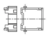
• When connecting Switches, fit the mating parts together.
• Do not push the (+) and (-) operating push-buttons at the same
time.
Do not
push here
Figure 2
Top surface
of board
Back surface
of board
Models with PCB Terminals
Do not use excessive force in handling the Switches. In particular,
take care to avoid dropping them because the terminals might bend
or break.
80° or less
Wipe away flux
with a brush.
• Using a Soldering Iron
Use a 30-W soldering iron at a temperature of 350°C for a
maximum of 3 seconds, and flush as described above.
Do not apply force to the terminals during soldering and for 3
minutes after soldering is completed. Doing so may result in
conduction or operation failure.
• Ensure that soldering flux and alcohol do not penetrate into the
Switch interior
5
�Terms and Conditions Agreement
Read and understand this catalog.
Please read and understand this catalog before purchasing the products. Please consult your OMRON representative if you
have any questions or comments.
Warranties.
(a) Exclusive Warranty. Omron’s exclusive warranty is that the Products will be free from defects in materials and workmanship
for a period of twelve months from the date of sale by Omron (or such other period expressed in writing by Omron). Omron
disclaims all other warranties, express or implied.
(b) Limitations. OMRON MAKES NO WARRANTY OR REPRESENTATION, EXPRESS OR IMPLIED, ABOUT
NON-INFRINGEMENT, MERCHANTABILITY OR FITNESS FOR A PARTICULAR PURPOSE OF THE PRODUCTS. BUYER
ACKNOWLEDGES THAT IT ALONE HAS DETERMINED THAT THE
PRODUCTS WILL SUITABLY MEET THE REQUIREMENTS OF THEIR INTENDED USE.
Omron further disclaims all warranties and responsibility of any type for claims or expenses based on infringement by the
Products or otherwise of any intellectual property right. (c) Buyer Remedy. Omron’s sole obligation hereunder shall be, at
Omron’s election, to (i) replace (in the form originally shipped with Buyer responsible for labor charges for removal or
replacement thereof) the non-complying Product, (ii) repair the non-complying Product, or (iii) repay or credit Buyer an amount
equal to the purchase price of the non-complying Product; provided that in no event shall Omron be responsible for warranty,
repair, indemnity or any other claims or expenses regarding the Products unless Omron’s analysis confirms that the Products
were properly handled, stored, installed and maintained and not subject to contamination, abuse, misuse or inappropriate
modification. Return of any Products by Buyer must be approved in writing by Omron before shipment. Omron Companies shall
not be liable for the suitability or unsuitability or the results from the use of Products in combination with any electrical or
electronic components, circuits, system assemblies or any other materials or substances or environments. Any advice,
recommendations or information given orally or in writing, are not to be construed as an amendment or addition to the above
warranty.
See http://www.omron.com/global/ or contact your Omron representative for published information.
Limitation on Liability; Etc.
OMRON COMPANIES SHALL NOT BE LIABLE FOR SPECIAL, INDIRECT, INCIDENTAL, OR CONSEQUENTIAL DAMAGES,
LOSS OF PROFITS OR PRODUCTION OR COMMERCIAL LOSS IN ANY WAY CONNECTED WITH THE PRODUCTS,
WHETHER SUCH CLAIM IS BASED IN CONTRACT, WARRANTY, NEGLIGENCE OR STRICT LIABILITY.
Further, in no event shall liability of Omron Companies exceed the individual price of the Product on which liability is asserted.
Suitability of Use.
Omron Companies shall not be responsible for conformity with any standards, codes or regulations which apply to the
combination of the Product in the Buyer’s application or use of the Product. At Buyer’s request, Omron will provide applicable
third party certification documents identifying ratings and limitations of use which apply to the Product. This information by itself
is not sufficient for a complete determination of the suitability of the Product in combination with the end product, machine,
system, or other application or use. Buyer shall be solely responsible for determining appropriateness of the particular Product
with respect to Buyer’s application, product or system. Buyer shall take application responsibility in all cases.
NEVER USE THE PRODUCT FOR AN APPLICATION INVOLVING SERIOUS RISK TO LIFE OR PROPERTY OR IN LARGE
QUANTITIES WITHOUT ENSURING THAT THE SYSTEM AS A WHOLE HAS BEEN DESIGNED TO ADDRESS THE RISKS,
AND THAT THE OMRON PRODUCT(S) IS PROPERLY RATED AND INSTALLED FOR THE INTENDED USE WITHIN THE
OVERALL EQUIPMENT OR SYSTEM.
Programmable Products.
Omron Companies shall not be responsible for the user’s programming of a programmable Product, or any consequence
thereof.
Performance Data.
Data presented in Omron Company websites, catalogs and other materials is provided as a guide for the user in determining
suitability and does not constitute a warranty. It may represent the result of Omron’s test conditions, and the user must correlate
it to actual application requirements. Actual performance is subject to the Omron’s Warranty and Limitations of Liability.
Change in Specifications.
Product specifications and accessories may be changed at any time based on improvements and other reasons. It is our
practice to change part numbers when published ratings or features are changed, or when significant construction changes are
made. However, some specifications of the Product may be changed without any notice. When in doubt, special part numbers
may be assigned to fix or establish key specifications for your application. Please consult with your Omron’s representative at
any time to confirm actual specifications of purchased Product.
Errors and Omissions.
Information presented by Omron Companies has been checked and is believed to be accurate; however, no responsibility is
assumed for clerical, typographical or proofreading errors or omissions.
2014.8
In the interest of product improvement, specifications are subject to change without notice.
OMRON Corporation
Industrial Automation Company
http://www.ia.omron.com/
(c)Copyright OMRON Corporation 2014 All Right Reserved.
�