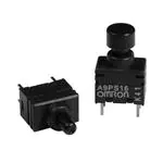
Ultra subminiature Pushbutton Switch
A9PS
Ultra subminiature size.
• Gold-plated clip contact ensure high reliability.
• The sealed bottom prevents flux penetration.
• Washable, equivalent to IP64 (IEC-60529).
• A9PS is smaller than A9P.
Height: A9P 13.3mm, A9PS 10.5mm (30% smaller than A9P)
RoHS Compliant
Typical Applications
Security Control Boards
Electric Power Instrumentation
Program Controllers
■
List of Models
Terminal Shape
DIP Terminal
Right Angle Terminal
Vertical Mount Terminal
Switching Functions
SPST
OFF
(ON)
A9PS16-0011
Quantity per tray
Note:
DPST
SPST
A9PS26-0011
A9PS16-0012
100
DPST
SPST
A9PS26-0012
A9PS16-0013
25
DPST
A9PS26-0013
50
(ON) shows Momentary.
● Caps
Available wide range og colors.
Colors
Models
White
Black
Blue
Green
Yellow
Red
A9PS-011
A9PS-021
A9PS-041
A9PS-051
A9PS-061
A9PS-071
4 dia.
Dimension
2.4
Dimension with the cap.
3.8
2.4
4 dia.
1
�A9PS
■
A9PS
Ratings/Characteristics
Rating (resistive load)
14 mA at 28 VAC/DC, 0.1 μA (minimum current) at 20 mVAC/DC
Ambient operating temperature
−20 °C to +80 °C 60% RH max. (with no icing or condensation)
Ambient operating humidity
45 to 85% RH (at +5 to +35 °C)
Insulation resistance
500 MΩ min. (at 500 VDC with insulation tester)
Contact resistance (initial value)
80 mΩ max.
Dielectric strength
500 VAC for 1min between terminals, between terminals and ground
Vibration resistance
Malfunction
10 to 55 Hz, 1.5-mm double amplitude
Shock resistance
Malfunction
500 m/s2 min.
Durability
Mechanical
50,000 operations min.
Electrical
50,000 operations min.
Degree of protection
IEC IP64
Washing
Possible
Operating forcse
4.9 N max.
Weight
0.3 g
■
Dimensions
●
DIP Terminal Models
(Unit: mm)
1.6
(5.6)
2.54
0.3
3.3
0.2
0.45
(6)
(3)
(6)
(3)
(4)
(1)
(4)
(1)
5.08 7
2 dia.
Stroke
1
Single Pole Type
Marking Side
Note:
●
Double Pole Type
NO.(4) and (6) terminals in the SPDT models are dummys to support the Switch case.
Right Angle Terminal Models
1.6
(5.6)
3.3
0.2 0.45
(3)
(6)
(3)
(1)
(4)
(1)
5.08 7
2 dia.
Stroke
Single Pole Type
1
Marking Side
0.3
2.6 3.1
5.08
Note:
2
2.54
Unless otherwise specified, a tolerance of ±0.4 mm applies to all dimensions.
Double Pole Type
�A9PS
●
A9PS
Vertical Mount Terminal Models
(5.6)
1.6
3.3
2.54
1
2 dia.
Stroke
0.3
0.45
(3)
(6)
(3)
(1)
(4)
(1)
7
2.6 3.6
1
Marking Side
5.08
Note:
■
Single Pole Type Double Pole Type
5.08
Unless otherwise specified, a tolerance of ±0.4 mm applies to all dimensions.
PCB Dimensions (Top View)
DIP Terminal Models
Right Angle Terminal Models
2.54
Four-0.6 +0.1
0 dia.
5.08
Four-0.6 +0.1
0 dia.
(3)
(4)
(1)
5.08
Six-0.6 +0.1
0 dia.
(3)
(6)
5.08
5.08
2.54
(1)
(6)
5.08
(1)
(4)
(3)
Single Pole Type
Double Pole Type
Vertical Mount Terminal Models
2.54
2.54
5.08
5.08
(1)
(4)
(1)
(6)
(3)
5.08
5.08
(3)
Six-0.6 +0.1
0 dia.
Four-0.6 +0.1
0 dia.
Single Pole Type
■
Double Pole Type
Switching Function / Internal Connections
Switching Functions
(3)
(3)
OFF
(ON)
1
1
(3)
DPST Models
4
Note:
1
1
SPST Models
(6)
4
(3)
(6)
(ON) shows Momentary.
3
�A9PS
A9PS
■ Safety Precautions
Be sure to read the Safety precautions common to all PCB-mount Manual Switch for correct use.
● Cautions
Use the switch within the rated voltage and current ranges,
otherwise the Switch may have a shortened life expectancy,
radiate heat,or burn out. This particularly applies to the
instantaneous voltages and currents when switching.
● Using Flux
Making mistakes in the type of flux or in the amount or method in
which it is applied can cause flux to enter the interior of the
Switch, with adverse effects on Switch performance. Assess the
proper flux, conditions,and methods prior to using it.
● Hardling
Do not apply excessive operating force to the Switch. Otherwise
the Switch may be damaged or deformed, and the switch
mechanism may malfunction as a result. Apply an operating force
not exceeding 9.8N {1,000gf}. Apply the operating load from the
top of the actuator. Do not apply a load from angle or from side
the actuator. Doing so may deform the Switch contact.
● RoHS Compliant
The "RoHS Compliant" designation indicates that the listed
models do not contain the six hazardous substances covered by
the RoHS Directive.
Reference: The following standards are used to determine
compliance for the six substances.
• Lead:
1,000 ppm max.
• Mercury:
1,000 ppm max.
• Cadmium:
100 ppm max.
• Hexavalent chromium: 1,000 ppm max.
• PBB:
1,000 ppm max.
• PBDF:
1,000 ppm max.
● Soldering
Observe the following conditions when soldering the Switch.
Automatic Soldering Bath
Soldering temperature: 260 °C max. (Preheating: 100 °C 120s max.)
Soldering time: 5s max.
Manual Soldering
Soldering temperature: 350 °C at the tip of the soldering iron.
Soldering time: 3s max.
● Washing
Apply alcohol based solvents to clean.
Do not clean the Switch immediately after soldering. Wait for at
least five minutes after soldering before cleaning.
Ultrasonic cleaning is not available dip into Switch washing
agents for two minutes maximum.
● Environment for Storage and Use
To prevent discoloration of the terminals and other problems
during storage, do not store the Switch in locations subject to the
following conditions.
1. High temperature or humidity
2. Corrosive gases
3. Direct sunlight
Also, the Switch is not waterproof or splash-resistance.
Do not use the Switch in locations that are subject to contact with
water. Do not subject the Switch to freezing or condensation.
• Application examples provided in this document are for reference only. In actual applications, confirm equipment functions and safety before using the product.
• Consult your OMRON representative before using the product under conditions which are not described in the manual or applying the product to nuclear control systems, railroad
systems, aviation systems, vehicles, combustion systems, medical equipment, amusement machines, safety equipment, and other systems or equipment that may have a serious
influence on lives and property if used improperly. Make sure that the ratings and performance characteristics of the product provide a margin of safety for the system or
equipment, and be sure to provide the system or equipment with double safety mechanisms.
Note: Do not use this document to operate the Unit.
OMRON Corporation
Electronic and Mechanical Components Company
Contact: www.omron.com/ecb
Cat. No. A198-E1-05
1014(0207)(O)
�
很抱歉,暂时无法提供与“A9PS16-0011”相匹配的价格&库存,您可以联系我们找货
免费人工找货- 国内价格
- 1+49.56770
- 10+36.09726
- 50+32.04733


 工商网监
湘ICP备2023018690号
工商网监
湘ICP备2023018690号

