CJ-series Serial Communications Units
CJ1W-SCU
CSM_CJ1W-SCU_DS_E_9_3
The Serial Communications
Units That Enable High-speed
Connections with External
Devices
• Each Serial Communications Unit provides two
serial communications ports: RS-232C and
RS-422A/485, and the serial communications
mode can be set separately for each port from
Protocol Macro, Host Link, NT Link, Serial
Gateway, and No-protocol.
CJ1W-SCU22
CJ1W-SCU32
CJ1W-SCU42
Features
• Mount a total of up to 16 CPU Bus Units, including these Serial Communications Units, to the CPU Rack or Expansion Racks to create systems
with up to 32 serial communications ports.
• Connect an NT-AL001 RS-232C/RS-442A Link Adapter to the RS-232C port to enable 1:N communications.
• With the CJ1W-SCU@2, you can use a faster baud rate (up to 230.4 kbps) and faster data transfer to the CPU Unit to enable connecting to
high-speed external devices.
System Configuration
Programing Devices
Host Computer
Modbus-RTU Master
(Host computers)
or
Serial Communications Units
CPU Unit
Programmable Terminal (PT)
RS-232C/RS-422A Adapter
NT-AL001
Protocol Macro
General-purpose External Device
No-protocol
General-purpose External Device
Serial Gateway
(Host Link(FINS))
CJ-series
Controller
(Host Link slave)
Serial Gateway
(Compoway/F)
Temperature Controller
Smart Sensor
1
�CJ1W-SCU
Ordering Infomation
International Standards
• The standards are abbreviated as follows: U: UL, U1: UL(Class I Division 2 Products for Hazardous Locations), C: CSA, UC: cULus, UC1: cULus (Class I Division
2 Products for Hazardous Locations), CU: cUL, N: NK, L: Lloyd, and CE: EC Directives.
• Contact your OMRON representative for further details and applicable conditions for these standards.
Specifications
Unit type
CJ1 CPU
Bus Units
Product name
Communications
Interface
Communications functions
Serial
Communications
Units
No. of unit
numbers
allocated
The following functions can be
selected for each port with an CJsystem:
• Protocol macro
• Host Link
• NT Links (1:N mode)
• Serial Gateway
• No-protocol *3
• Modbus-RTU Slave
High-speed type
2 RS-232C ports
Current
consumption (A)
5V
24V
0.28
*1
—
Model
Standards
CJ1W-SCU22 *2
UC1, N,
L, CE
1
The following functions can be
2 RS-422A/485 ports selected for each port with an NJsystem:
• Protocol macro
• Serial Gateway
• No-protocol
1 RS-232C port and
• Modbus-RTU Slave
1 RS-422A/485 port
CJ1 CPU
Bus Units
Serial
Communications
Units
The following functions can be
selected for each port:
• Protocol macro *4
• Host Link
• NT Links (1:N mode)
2 RS-422A/485 ports • Serial Gateway *5
• No-protocol *6
• Modbus-RTU Slave *7
1 RS-232C port and
1 RS-422A/485 port
2 RS-232C ports
1
0.40
—
CJ1W-SCU32 *2
0.36
*1
—
CJ1W-SCU42 *2
0.28
*1
—
CJ1W-SCU21-V1 *8
0.38
—
CJ1W-SCU31-V1 *8
0.38
*1
—
CJ1W-SCU41-V1 *8
UC1, N,
L, CE
*1. When an NT-AL001 RS-232C/RS-422A Conversion Unit is used, this value increases by 0.15 A/Unit.
*2. Sinple Backup Function and Interrupt notification function cannot be used with an NJ-system.
*3. A Serial Communications Unit with unit version 2.1 or later, a CPU Unit with unit version 1.03 orlater, and Sysmac Studio version 1.04 or higher
are required to use the SerialRcvNoClear instruction.
*4. You can activate Protocol macro trace function when the CPU Unit is set to the RUN/MONITOR mode. (MONITOR mode is not available with
the NJ-series CPU Units.)
*5. The Serial Gateway function is enabled only for Serial Communications Units of unit version 1.2 and later.
*6. The no-protocol function is enabled only for Serial Communications Units of unit version 1.2 and later (and a CS1/CJ1 CPU Unit of unit version
3.0 or later or a CJ2 CPU Unit is also required).
*7. The Modbus-RTU Slave function is enabled only for Serial Communications Units of unit version 1.3 and later.
*8. This unit cannot be used, with the Machine Automation Controller NJ-series.
Accessories
Model
Accessories
Specifications
CJ1W-SCU32
2 Serial Port (RS-422A/485) Connector
Terminal Block Connector (FMC1.5/5-STF-3.5AU by Phoenix Contact)
CJ1W-SCU42
1 Serial Port (RS-422A/485) Connector
Terminal Block Connector (FMC1.5/5-STF-3.5AU by Phoenix Contact)
Note: A serial port connector is not provided. Purchase a connector separately for serial port connection.
Plug : XM3A-0921 (manufactured by OMRON) or equivalent
Hood : XM2S-0911-E (manufactured by OMRON) or equivalent
Mountable Racks
NJ system
Model
CJ1W-SCU22
Unit version 2.0
CJ1W-SCU32
Unit version 2.0
CJ1W-SCU42
Unit version 2.0
CJ1W-SCU21-V1
Unit version 1.3
CJ1W-SCU31-V1
Unit version 1.3
CJ1W-SCU41-V1
Unit version 1.3
CPU Rack *5
Expansion
Rack *5
10 Units
10 Units
(per Expansion
Backplane)
CJ system (CJ1, CJ2)
CP1H system
NSJ system *1
CPU Rack
Expansion
Backplane
CP1H PLC
NSJ
Controller
Expansion
Backplane
10 Units *2
10 Units *3
(per Expansion
Backplane)
2 Units *4
Not supported
10 Units *3
(per Expansion
Backplane)
Not supported
Note: It may not be possible to mount this many Units to a Rack depending on the current consumption of the other Units.
*1. Product no longer available to order.
*2. This is the number of Units for a CJ2H-CPU6@ CJ2H CPU Unit (without EtherNet/IP) and a CJ1W-PA205@ or CJ1W-PD025 Power Supply
Unit. (When not using NT-AL001)
*3. This is the number of Units for a CJ1W-PA205@ or CJ1W-PD025 Power Supply Unit.
*4. A CP1W-EXT01 CJ Unit Adaptor is required
*5. A total of up to 16 Units, including all other CPU Bus Units.
2
�CJ1W-SCU
Specifications
Item
Description
Device name
Serial Communications Unit
Classification
CPU Bus Unit
Model number
Serial ports
Protocol
Number of
mountable
Units
CJ1W-SCU22
CJ1W-SCU32
CJ1W-SCU42
CJ1W-SCU21-V1
CJ1W-SCU31-V1
CJ1W-SCU41-V1
Port 1
RS-232C
RS-422A/485
RS-422A/485
RS-232C
RS-422A/485
RS-422A/485
Port 2
RS-232C
RS-422A/485
RS-232C
RS-232C
RS-422A/485
RS-232C
Port 1
Host Link, protocol macro, Serial Gateway, No-protocol, NT Link, Host Link, protocol macro, NT Link, or loopback test can be
Modbus-RTU Slave, loopback test , or 1:1 Host Link can be se- selected for each port.
lected for each port. *1 *2
• Unit Ver. 1.2 or later also supports Serial Gateway, no-protocol, and 1:1 Host Link modes. (Note: The Serial Gateway can
also be executed in protocol macro mode.) *1
• Unit Ver. 1.3 or later also supports Modbus-RTU slave mode.
Port 2
CPU Unit
None
CPU Rack
A total of up to 16 Units, including all other CPU Bus Units. No
restrictions on the mounting location.
However, if an external interrupt task is used, the Unit must be
mounted in one of the following slots on the CPU Rack.
• CJ2H-CPU6@-EIP CPU Unit: Slots 0 to 3
A total of up to 16 Units, including all other CPU Bus Units. No
• CJ2H-CPU6@, CJ2M-CPU@@ or CJ1G/H-CPU@@H CPU Unit:
restrictions on the mounting location.
Slots 0 to 4
• CJ1M-CPU@@ CPU Unit *4: Slots 0 to 2
External interrupt tasks will not be started if the Unit is mounted to
any other slot.
Expansion
Rack
Ordinary
refreshing
of software Allocated 25 words of the 25 words in the CPU Bus Unit CIO Area (constant data exchange with the CPU Unit)
switches
and status
Data exchange
with the CPU Unit Transfer
from the
CPU Unit
set by the
system
Simple Backup Function
Of the CPU Bus Unit DM Area, each serial port is allocated 10 words (total 20 words).
Data is transferred from the CPU Unit at the following times:
• Startup or restart
• Ladder instruction: STUP(237)
• Port Settings Changing Flag turns ON (Auxiliary Area)
The CPU Unit’s Simple Backup Function can be used to backup the Protocol Macro data in the Serial Communications Unit to the
CPU Unit’s Memory Card. The backed-up data can be restored or compared.
(The Simple Backup Function can be used with the CJ1-H and CJ1M CPU Units only.)
Current consumption *3
280mA+x
400mA
360mA+x
280mA+x
380mA
380mA+x
Weight
160g Max.
120g Max.
140g Max.
110g Max.
110g Max.
110g Max.
General specifications
Conforms to general specifications for CJ Serise.
*1. Serial Gateway: The Serial Gateway can also be executed in protocol macro mode.
*2. No-protocol: An external interrupt task can be executed when data is received in No-protocol Mode. If the CJ2H CPU Units with unit version
1.1 or later and CJ2M CPU Units is used, the high-speed communications instructions (DRXDU(261) and DTXDU(262)) can also be used.
*3. The current consumption is for one Serial Communications Unit. When an NT-AL001 Link Adapter is connected to the Serial Communications
Unit, power is supplied to the Link Adapter from the Unit. A current consumption of 0.15A must be added for each Link Adapter that is
connected. In the above specifications, “x” indicates that 0.15A must be added for each port to which an NT-AL001 Link Adapter is connected
to provide the required 5-V power supply.
*4. Final order entry date for CJ1M:The end of March, 2021
3
�CJ1W-SCU
Protocol Specifications
Host Link Specifications
Item
Description
Communications mode
Half-duplex (Full-duplex for slave-initiated communications)
Synchronous mode
Start-stop synchronization (asynchronous mode)
Baud rate *1
RS-232C port and RS-422A/485 ports:
1,200/2,400/4,800/9,600/19,200/38,400/57,600/115,200/230,400 bps *2
Default setting: 9,600 bps
Communications distance
*1
RS-232C port
: 15 m max. *3
RS-422A/485 Port :
• CJ1W-SCU@1-V1
500 m max. (total cable length: 500 m max., T-branch branch lines: 10 m max.)
• CJ1W-SCU@2
1,200 m max. (total cable length: 1,200 m max., Multidrop connections are possible. However, maximum cable length is 500 m if
the NT-AL001 is used for RS-422A-485 connections.)
Connection configuration
RS-232C port
: 1:1 (1:N (N = 32 Units max.) is possible using an Converting Link Adapters.)
RS-422A/485 port : 1:N (N = 32 Units max.)
Number of connected Units
32 Units max. (unit numbers 0 to 31; unit number 0 is set for 1:1 connection)
C-mode commands
Header: @, address: (host link unit number) 0 to 31 (BCD), data: header code + text, error check
code: FCS, terminator: * +CR
FINS commands
Header: @, address: (host link unit number) 0 to 31 (BCD), data: header code (always “FA”) + FINS
header + FINS command + text, error check code: FCS, terminator: * +CR
Frame structure
Vertical parity: Even, odd. or none
FCS (horizontal parity converted to ASCII)
Error check codes
Command flow
Command flow and support
Host computer to Controller
Controller to host computer
Commands
Contents
C-mode commands
1:1 or 1:N communications with directly connected Controller *4
FINS commands
1:1 or 1:N communications with directly connected Controller.
(in Host Link protocol)
FINS commands
Communications using SEND(090), RECV(098), and CMND(490) from CPU
(in Host Link protocol) Unit. *5
*1. Confirm the baud rates and communications distance supported by connected devices.
*2. The CJ1W-SCU@2 is required for communications at 230,400 bps.
*3. The maximum cable length for RS-232C is 15 m. The RS-232C standard, however, does not cover baud rates above 19.2 Kbps. Refer to the
manual for the device being connected to confirm support.
*4. The specified frame format must be prepared on the host computer and then sent.
*5. The host computer must interpret the commands and return a response in the correct format.
Connection between the host computer and Controller must be 1:1.
Protocol Macro Function Specifications
Item
Number of protocols
20 max.
Number of sequences
1,000 max.
Per protocol
Description
Can be created and registered with the Protocol Support Tool (CX-Protocol).
Number of sequences
60 max.
Number of messages
300 max.
Number of reception
matrixes
100 max.
Sequence execution condition
Using the CPU Unit’s PMCR (260) instruction (specifying the sequence number)
Communications mode
Half-duplex or full-duplex
Synchronous mode
Start-stop synchronization (asynchronous mode)
Baud rate *1
RS-232C port and RS-422A/485 ports:
1,200/2,400/4,800/9,600/19,200/38,400/57,600/115,200/230,400 bps
Default setting: 9,600 bps *2
Communications distance *1
RS-232C port
: 15 m max.
RS-422A/485 port :
• CJ1W-SCU@1-V1
500 m max. (total cable length: 500 m max., T-branch branch lines: 10 m max.)
• CJ1W-SCU@2
1,200 m max. (total cable length: 1,200 m max., Multidrop connections are possible. However, maximum cable length is 500 m if the NT-AL001 is used for RS-422A-485 connections.)
Connection configuration
RS-232C port
: 1:1 (1:N (N = 32 Units max.) is possible using a Converting Link Adapter.)
RS-422A/485 port : 1:N (N = 32 Units max.)
Number of connected Units
32 Units max. (unit numbers 0 to 31; unit number 0 is set for 1:1 connection)
Maximum number of data
exchange words between
Controller and protocol
macro function
Including the word that specifies the number of
words (1 word)
Operand setting
250 words
Link word setting
500 words
O1, O2, I1, and I2: 500 words total
Direct setting
500 words
Maximum number of words per data attribute
4
�CJ1W-SCU
Item
Description
Number of steps per
sequence
16 max.
Transmission control
parameters
X-on/X-off flow, RS/CS flow, delimiter control, or contention control, and modem control can be
selected.
Scan notification: Writes the receive data to I/O memory during CPU Unit scanning.
Sequence contents
(step common parameters)
Step contents
Response notification
method (operand)
Scan method (fixed)
Support
Interrupt notification
Not support
Interrupt notification for reception case number
Not suppprt
Monitoring time during
send/receive processing
Receive wait, receive completion, or send completion can be monitored.
Setting range: 0.01 to 0.99 s, 0.1 to 9.9 s, 1 to 99 s, or 1 to 99 minutes
Link word setting
Area in which data is exchanged between the CPU Unit and the Serial Communications Unit during
Communications Unit refreshing.
Two areas are possible for each device: An area for storing receive data and an area for storing send
data. *3
Commands
Send only (SEND), receive only (RECV), send and receive (SEND&RECV), wait (WAIT), reception
buffer clear (FLUSH), ER-ON (OPEN), or ER-OFF (CLOSE)
Repeat counter
1 to 255 times
Retry count
0 to 9 (Only when the command is SEND&RECV)
Send wait time
0.01 to 0.99 s, 0.1 to 9.9 s, 1 to 99 s, or 1 to 99 minutes
(Only when the command is SEND or SEND&RECV)
With or without response
write (operand)
When receive processing is completed (when the receive data is stored in the area specified in the
4th operand of the PMCR(260) instruction), whether or not to store the received messages can be
selected.
Next processing
When a step has ended normally, End (sequence completed), Next (proceed to the next step No.),
Goto (go to the specified step No.), or Abort (interrupt the step and terminate that sequence) can be
selected.
Error processing
When a step has ended abnormally, End, Next, Goto, or Abort can be selected.
Send message
Data sent to the specified address when the
command is SEND or SEND&RECV.
Receive message
Data sent from the specified address when the
command is RECV or SEND&RECV.
Reception matrix
When the command is RECV or SEND&RECV,
sets the expected receive messages (15 max.),
and switches to the next processing according to
the message received.
Header and
terminator data
attributes
Consists of a header, address, length, data,
error check code, and terminator.
Specifies the receive messages and the next
processing for each of cases No. 00 to No. 15.
Of the maximum 16 cases, one case must be
set as “Other” in the receive messages (in
addition to the set receive messages).
Constant
ASCII data, hexadecimal data, or control code
Constant
ASCII data, hexadecimal data, or control code (with an address, no control code is possible)
No conversion, conversion to ASCII data, or conversion to hexadecimal data
(the read/write direction can be specified)
Designa- (X, Y)
tion
X: Effective address (where read from, or where written to)
method
Y: Data size (1 to 1,000) *4
Message unit contents
Data attributes of
addresses and data
in send/receive
messages
Word read
(I/O memory to send
data)
Variable
Specify using a link
word.
I/O memory direct
designation
Word
designation
X
Specify using the
3rd operand of the
PMCR(260) instruction.
Word write
(receive data to I/O
memory)
Specify using the
4th operand of the
PMCR(260) instruction.
Set leading address + n
(The linear expression
aN + b, including
repeat counter N, is
also possible for n.)
Specify using a link
word.
I/O memory direct
designation
Wild card
*
Repeat
counter
N
Any data or address can be received
(only in receive messages)
5
�CJ1W-SCU
Item
Description
Data attributes of
addresses and data
in send/receive
messages
Variable
Linear expression including aN+b
repeat counter
a: 0 to 1000; b: 1 to 1000
N: Repeat counter value
Wild card
Can be received regardless of the length
(only in receive messages)
*
Y
Word read
Word designa(I/O memory to send
tion
data)
Message unit contents
Specify using the
3rd operand of the
Set leading address + n
PMCR(260) instruction.
(The linear expression
Specify using a link
aN + b, including
word.
repeat counter N, is
also possible for n.)
I/O memory direct
designation
Error check codes
LRC, LRC2, CRC-CCITT, CRC-16, SUM, SUM1, and SUM2 can be calculated.
Maximum length of
send/receive messages
1,000 bytes. (A maximum length between 200 and 1,000 bytes can be set in the Setup Area.)
Maximum number of data
attributes registered in one
message
96 attributes *5
Maximum number of write
data attributes registered in
one message
30 attributes *6
• A total of up to 1,700 bytes (characters) of time-series data can be traced in send and receive
messages.
• Changes to the step No. and control signals such as RS and CS can also be traced.
Trace function *7
*1. The baud rate and the communications distance sometimes depend on the remote device.
*2. A baud rate of 57,600 bps can be selected when using Unit Ver. 1.2 or later (115,200 bps is not possible). The CJ1W-SCU@2 is required for
communications at 115,200 or 230,400 bps.
*3. Unit Ver. 1.2 or later supports continuous I/O refreshing in addition to the previous on-request I/O refreshing.
*4. The data size is the number of bytes on the transmission path.
*5. The CX-Protocol can be used to register up to 96 attributes per message.
*6. A macro syntax error will occur when the protocol macro is executed if more than 31 write attributes are registered in one message.
*7. The CPU Unit is set to the RUN/MONITOR mode. (MONITOR mode is not available with the NJ-series CPU Units.)
Note: When using 2-wire RS-422A/485 communications in Protocol Macro Mode, set only modem controls for the send control parameters,
and do not use RS/CS flow controls.
Serial Gateway Specifications
Item
Description
Conversion source
FINS commands (received through network (including Host Link FINS) or CPU bus)
Conversion functions
• The received FINS command sent to the Unit’s serial port is converted according to the FINS command code as follows:
2803 hex: FIN header removed and converted to Compo-Way/F command.
2804 hex: FIN header removed and converted to Modbus-RTU command.
2805 hex: FIN header removed and converted to Modbus-ASCII command.
The converted command is sent to the serial port.
• When the received FINS command is sent to the Unit (user-specified FINS command code), the FINS command is enclosed
in a Host Link header and terminator.
Converted format
•
•
•
•
Enabled serial
communications mode
Serial Gateway mode or protocol macro mode
Queuing functions
Up to five FINS commands can be converted and then queued for processing.
Protocol macro execution
processing
When a FINS command is received during protocol macro execution, the Serial Gateway is executed using an interrupt between
steps in the communications sequence. If the next step is a RECEIVE command, the Serial Gateway will not be executed until the
next step. For other conditions, the interrupt is executed immediately. *1
Response timeout
monitoring
The time is monitored from when the message is converted into the specified protocol using the Serial Gateway until the response is
received (in Serial Gateway mode or protocol macro mode).
Default: 5 s (setting range: 0.1 to 25.5 s) *2
Send start timeout
monitoring
The time is monitored from when the FINS command is received until it is converted into the specified protocol and starts to be sent
(in protocol macro mode only).
Default: 5 s (setting range: 0.1 to 25.5 s) *3
Send delay
The time can be set from when the message is converted into another protocol using Serial Gateway conversion until the data is
actually sent. (Serial Gateway or protocol macro mode)
Default: 0 s (setting range: 0.01 to 300.00 s)
CompoWay/F commands
Modbus-RTU commands
Modbus-ASCII commands
Host Link FINS commands
*1. The reception buffer is cleared during Serial Gateway execution.
The Serial Gateway can be prohibited in protocol macro mode by turning ON the Serial Gateway Prohibit Switch in the CIO Area.
*2. When a timeout occurs, the FINS end code (0205 hex: Response timeout) is returned to the source of the FINS command and a response is
received after a timeout occurs.
*3. When a timeout occurs, the FINS end code (0204 hex: Remote node busy) is returned to the source of the FINS command. The send
processing will not be executed and the received FINS command will be discarded.
6
�CJ1W-SCU
No-protocol Specifications
Item
Description
Communications mode
Full-duplex
Baud rate *1
RS-232C port and RS-422A/485 ports: 1,200/2,400/4,800/9,600/19,200/38,400/57,600/115,200/230,400 bps *2
Default setting: 9,600 bps
Communications distance
*1
RS-232C port
: 15 m max.
RS-422A/485 port :
• CJ1W-SCU@1-V1
500 m max. (total cable length: 500 m max., T-branch branch lines: 10 m max.)
• CJ1W-SCU@2
1,200 m max. (total cable length: 1,200 m max., Multidrop connections are possible. However, maximum cable length is 500 m if
the NT-AL001 is used for RS-422A-485 connections.)
Messages
(communications frame
structure)
Set either of the following types in the Setup Area in the allocation DM Area.
1. Data only (without start code and end code)
2. Start code + data
3. Data + end code
4. Start code + data + end code
5. Data + CR + LF
6. Start code + data +CR + LF
Set in allocated DM Area
(The start code can be included by setting it to between 00 and FF hex, and the end code can be included by setting it to between
00 and FF hex. To exclude the end code, set the number of receive data bytes.)
Start code
Sending messages
Receiving messages
None or 00 to FF hex
End code
None, 00 to FF hex, or CR + LF
Number of receive data bytes
during reception
Set the number of receive data bytes between 1 and 256 bytes (according to the DM Area settings)
when frame structure 1 or 2 above is used.
CJ: TXDU(256) instruction *3
NJ: SerialSend instruction
CJ: RXDU(255) instruction *3
NJ: SerialRcv or SerialRcvNoClear instruction *4
Maximum message length
Sending and receiving: Up to 259 bytes including the start code and end code (up to 256 bytes excluding start/end codes)
Data conversion
No conversion
Communications protocol
None
Message delay time
CJ: When the TXD (236), TXDU (256) instruction is executed, after the send delay time, the data is sent from the port. *3
0 to 300 s (0 to 300,000 ms)
(Can be set in 10-ms units depending on the DM Area settings)
NJ: When the SerialSend instruction is executed, after the send delay time, the data is sent from the port.
0 to 300 s (0 to 300,000 ms)
(Can be set in 10-ms units: Set in System Studio or by using a device variable for CJ-series Unit.)
Receive counter
The number of data bytes (0 to 256) received at the port can be counted.
Reception buffer clear
timing
• CJ1W-SCU@1-V1
The reception buffer is cleared immediately after executing the RXD(235)/RXDU(255) instruction
• CJ1W-SCU@2
With the DRXDU(261) instruction, you can specify whether the reception buffers will be cleared or not in a setting in the DM Area
words allocated to the Unit. *3
• NJ: SerialRcv instruction: After reading the receive data
SerialRcvNoClear instruction: When the receive data size variable (Size) is set to 0 *4
*1. The baud rate and the communications distance sometimes depend on the remote device.
*2. The CJ1W-SCU@2 is required for communications at 115,200 or 230,400 bps.
*3. The DTXDU (262) and DRXDU (261) instructions can be used only when a CJ1W-SCU@2 Serial Communications Unit is connected to the
CJ2H CPU Units with unit version 1.1 or later and CJ2M CPU Units.
*4. A Serial Communications Unit with unit version 2.1 or later, a CPU Unit with unit version 1.03 or later, and Sysmac Studio version 1.04 or higher
are required to use the SerialRcvNoClear instruction.
Modbus-RTU Specifications
Item
Description
Mode
Modbus-RTU slave mode *1
Baud rate
1,200/2,400/4,800/9,600/19,200/38,400/57,600/115,200/230,400 bps *2
Default: 19,200 bps
Data length
8 bits
Parity
Odd, even, or none
Default: Even
Stop bits
Odd or even parity :1 bit
No parity
: 2 bits
Address setting range
1 to 247 (broadcasting: 0)
Frame format
Slave address : 1 byte
Function code : 1 byte
Data
: 0 to 252 bytes
CRC code
: 2 bytes
*1. Modbus-ASCII mode is not supported.
*2. The CJ1W-SCU@2 is required for communications at 230,400 bps.
7
�CJ1W-SCU
Supported Commands
Function code
(hexadecimal)
Function
Modbus name
01
Reads multiple bits from the CIO, Work, Holding, or Auxiliary Area of I/O memory.
Read Coils
02
Reads multiple bits from the CIO Area of I/O memory.
Read Discrete Inputs
03
Reads multiple words from the DM or EM Area of I/O memory.
Read Holding Registers
04
Reads multiple words from the CIO, Work, Holding, or Auxiliary Area of I/O memory.
Read Input Registers
05
Writes a bit in I/O memory.
Write Single Coil
06
Writes a word in the DM or EM Area of I/O memory.
Write Single Register
08
Executes an echoback test.
Diagnostic
0F
Writes multiple bits in I/O memory.
Write Multiple Coils
10
Writes multiple words in the DM or EM Area of I/O memory.
Write Multiple Registers
Unit Version and Manufacturing Dates/Lot Numbers
CJ1W-SCU@1-V1
Classification
Type
Model
CJ1W-SCU21-V1
CPU Bus Units
Support
Software
May 2004
June 2004
November 2005
Per-Ver 1.2
Unit version 1.2
Unit version 1.3
(Lot No:040617 and later)
CJ1W-SCU31-V1
—
—
Unit version 1.3 *
—
Ver.4.0 or earlier
Ver.5.0
Ver.6.1
Ver.1.4 or earlier
Ver.1.5
Ver.1.7
Serial Communications
Units
CJ1W-SCU41-V1
CX-Programmer
CX-Protocol
—
* Available April, 2006
CJ1W-SCU@2
Classification
Type
Model
September 2009
September 2012
CJ1W-SCU22
CPU Bus Units
Serial Communications
Units
CJ1W-SCU32
Unit version 2.0
Unit version 2.1 *1
CJ1W-SCU42
Support
Software
Machine
Automation
Controller
CX-Programmer
—
Ver.8.3 or higher
CX-Protocol
—
Ver.1.9 or higher
Sysmac Studio
形SYSMAC-SE□
Ver.1.04 or higher
形NJ5-□□□□
Ver.1.00 or earlier *
形NJ3-□□□□
Ver.1.01 or earlier *
CPU Unit
* A Serial Communications Unit with unit version 2.1 or later, a CPU Unit with unit version 1.03 or later, and Sysmac Studio version 1.04 or higher
are required to use the SerialRcvNoClear instruction.
8
�CJ1W-SCU
Function Support by Unit Version
Function Support by Unit Version 2.1
Unit version
Unit version 2.1
CJ1W-SCU22
CJ Series
Serial Communications Units model
CJ1W-SCU32
Functions
CJ1W-SCU42
Noprotocol
NJ: SerialRcvNoClear instruction
Supported
Function Support by Unit Version 2.0
Product
Unit version 2.0
CJ1W-SCU22
CJ Series
Serial Communications Units
CJ1W-SCU32
CJ1W-SCU42
Serial gateway
Functions
Host Link
Supported
1:1 links
Supported
Host Link compatible device
selection
Supported
No-protocol
Protocol
macro
Supported
Link word specification data
exchange timing
On-request I/O refreshing
Continuous I/O refreshing
Reception buffer processing for
PMCR(260) instruction execution
Select to clear or hold contents.
Baud rate (bps)
230,400 supported.
Standard system protocol additions
Supported
MODBUS slave protocol added
Supported
Function Support by Unit Version 1.2 and Unit Version 1.3
Earlier version
(pre-ver. 1.2)
Product
CJ Series
Serial Communications Units
Serial gateway
Host Link
Unit version 1.3
CJ1W-SCU21
CJ1W-SCU21-V1
—
—
CJ1W-SCU21-V1
CJ1W-SCU31-V1
CJ1W-SCU41
CJ1W-SCU41-V1
CJ1W-SCU41-V1
Not supported
Supported
Supported
1:1 links
Not supported
Supported
Supported
Host Link compatible device
selection
Not supported
Supported
Supported
No-protocol
Functions
Unit version 1.2
Not supported
Supported
Supported
Link word specification data
exchange timing
On-request I/O refreshing only
On-request I/O refreshing
Continuous I/O refreshing
On-request I/O refreshing
Continuous I/O refreshing
Reception buffer processing for
PMCR(260) instruction execution
Clearing only
Select to clear or hold contents. Select to clear or hold contents.
Baud rate (bps)
38,400 max.
(57,600 and 115,200 not
supported)
57,600 supported.
57,600 supported.
Standard system protocol additions
Not supported
Supported
Supported
MODBUS slave protocol added
—
—
Supported
Protocol
macro
Note: Make sure that a CS1/CJ1 CPU Unit of unit version 3.0 or later or a CJ2 CPU Unit is used when using no-protocol mode.
9
�CJ1W-SCU
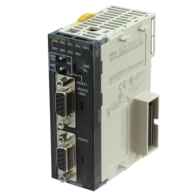
External Interface
Serial Communications Units provide two communications ports for external interface: RS-232C and/or RS-422A/485 ports.
CJ1W-SCU41-V1
RUN
ERC
SD1
RD1
RDY
ERH
SD2
RD2
SCU41-V1
RUN
ERC
SD1
RD1 TER1
RDY
ERH
SD2
RD2
Indicators
ON
WIRE
2
4
3456
F 012
F 012
BCDE
PORT1
TERM
OFF
BCDE
Unit number
switch
RUN
ERC
SD1
RD1 TER1
RDY
ERH
SD2
RD2
UNIT
NO.
PORT1
(RS422
/485)
Port 1:
RS-232C
Terminating
resistance switch
Unit number
switch
2-wire/4-wire
switch
Port 1:
RS-422A/485
Indicators
TERM
OFF
ON
WIRE
2
4
3456
789A
UNIT
NO.
789A
789A
3456
SCU42
Indicators
F 012
SCU21-V1
CJ1W-SCU42
BCDE
CJ1W-SCU21-V1/SCU22
UNIT
NO.
PORT1
(RS422
RDA- /485)
RDA+
SDA-
PORT2
SCU31-V1
RUN
ERC
SD1
Port 2:
RS-232C
SCU32
RD1 TER1
RUN
ERC
SD1
RD1 TER1
RDY
ERH
SD2
RD2 TER2
UNIT
NO.
Terminating
resistance switch
(for port 1)
ON
WIRE
2
4
3456
Unit number
switch
PORT1
(RS422
/485)
2-wire/4-wire
switch (for port 1)
Port 1:
RS-422A/485
PORT2
(RS422
/485)
Port 2:
RS-422A/485
TERM
OFF
WIRE
2
TERM
OFF
F 012
F 012
4
BCDE
WIRE
2
3456
Indicators
ON
4
789A
ON
789A
TERM
OFF
RD2 TER2
BCDE
SD2
ERH
Port 2:
RS-232C
CJ1W-SCU32
Indicators
RDY
2-wire/4-wire
switch
PORT2
Port 2:
RS-232C
CJ1W-SCU31-V1
Unit number
switch
Port1:
RS-422A/485
terminal-block
Connector
SDA+
FG
PORT2
Terminating
resistance switch
RDARDA+
UNIT
NO.
Magnified view of bottom-right
corner
Unit number
switch
PORT1
(RS422
/485)
2-wire/4-wire
switch (for port 1)
SDASDA+
FG
Port1:
RS-422A/485
terminal-block
Connector
PORT2
(RS422
RDA- /485)
RDA+
SDASDA+
FG
Terminating
resistance switch
(for port 1)
TERM
OFF
WIRE
2
ON
Port2:
RS-422A/485
terminal-block
Connector
Terminating
resistance switch
(for port 2)
2-wire/4-wire switch
(for port 2)
4
10
�CJ1W-SCU
Specifications of the RS-232C port and RS-422A/485 port
RS-232C Port
Protocol
Host Link
Protocol macro
Communications
method
Full-duplex
Synchronization
Start-stop synchronization (asynchronous)
Baud rate
1,200/2,400/4,800/9,600/19,200/38,400/57,600/115,200/230,400 bps *1
Connections
1:1 (1:N is possible using Link Adapters)
Transmission distance
15 m max. *3
Interface
Complies with EIA RS-232C
Protocol
1:N NT Links
Full-duplex or half-duplex
No-protocol
Half-duplex
Standard NT link or high-speed NT link *2
Serial Gateway
Modbus-RTU
Communications
method
Full-duplex
—
—
Synchronization
—
—
—
Baud rate
1,200/2,400/4,800/9,600/19,200/38,400/57,600/115,200/ 230,400 bps *1
Connections
1:1 (1:N is possible using Link Adapters)
Transmission
distance
15 m max. *3
Interface
Complies with EIA RS-232C
*1. The CJ1W-SCU@2 is required for communications at 230,400 bps.
*2. High-speed NT link is only available with Serial Communications Units manufactured on or after December 20th, 1999. With earlier models,
only standard NT link is available.
*3. The maximum cable length for RS-232C is 15 m. The RS-232C standard, however, does not cover baud rates above 19.2 Kbps. Refer to the
manual for the device being connected to confirm support.
Connector Pin Layout
Pin No.
Abbreviation
1 *1
Signal name
FG
Shield
2
SD
Send data
3
RD
Receive data
4 *2
RTS (RS)
Request to send
5 *2
CTS (CS)
Clear to send
6 *3
5V
Power supply
7 *2
DSR (DR)
8 *2
DTR (ER)
Data set ready *4
Data terminal ready
I/O
—
9
5
Output
Input
Output
Input
—
6
Input
1
Output
9
SG
Signal ground
—
Shell *1
FG
Shield
—
*1. Pin No. 1 and the shell are connected to the ground terminal (GR) of the Power Supply Unit inside of the Serial Communications Unit.
Therefore, the cable shield can be grounded by grounding the GR of the Power Supply Unit.
*2. The status of the RTS (RS), CTS (CS), DSR (DR), and DTR (ER) signals can be monitored in the words allocated in the CIO Area. For details,
refer to 2-3 I/O Memory Allocations.
*3. Pin 6 (5 V) is required when the NT-AL001 Link Adapter is connected.
*4. The DSR signal is used to monitor the signal cable. It can also be used as a CD (carrier detect) signal. (The DSR signal does not affect system
operation, and is available for use by the user.)
Note: Do not connect the 5-V power supply of Pin 6 to any external device other than an NT-AL001 Link Adapter. Otherwise, the external device
and the Serial Communications Unit may be damaged.
The following cables are provided for connection to NT-AL001 Link Adapters. We recommend that these cables be used.
NT-AL001 connecting cables: XW2Z-070T-1 (0.7 m)
XW2Z-200T-1 (2 m)
Applicable Connectors
Plug : XM3A-0921 (manufactured by OMRON) or equivalent
Hood : XM2S-0911-E (manufactured by OMRON) or equivalent
Recommended Cables
UL2426 AWG28 × 5P IFS-RVV-SB (UL-approved, Fujikura Ltd.)
AWG28 × 5P IFVV-SB (not UL-approved, Fujikura Ltd.)
UL2426-SB (MA) 5P × 28AWG (7/0.127) (UL-approved, Hitachi Metals, Ltd.)
CO-MA-VV-SB 5P × 28AWG (7/0.127) (not UL-approved, Hitachi Metals, Ltd.)
Cable length: 15 m max.
11
�CJ1W-SCU
RS-422A/485 Port
Protocol
Host Link
Protocol macro
1:N NT Links
Communications
method
Full-duplex
Synchronization
Start-stop synchronous (asynchronous)
Baud rate
1,200/2,400/4,800/9,600/19,200/38,400/57,600/115,200/230,400 bps *1
Standard NT link or high-speed NT link *2
Connections
1:N (N: 32 Units max.)
1:N (N: 8 Units max.)
Transmission distance
500 m max. (The total combined cable length is 500 m max. Tbranch lines must be a maximum of 10 m long.)
Interface
Complies with EIA RS-485
Protocol
Full-duplex or half-duplex
No-protocol
Half-duplex
Serial Gateway
Modbus-RTU
Communications
method
Full-duplex
—
—
Synchronization
—
—
—
Baud rate
1,200/2,400/4,800/9,600/19,200/38,400/57,600/115,200/ 230,400 bps *1
Connections
1:N (N: 32 Units max.)
Transmission distance
500 m max. (The total combined cable length is 500 m max. Tbranch lines must be a maximum of 10 m long.)
Interface
Complies with EIA RS-485
*1. The CJ1W-SCU@2 is required for communications at 230,400 bps.
*2. High-speed NT link is only available with Serial Communications Units manufactured on or after December 20th, 1999. With earlier models,
only standard NT link is available.
Connector Pin Layout (CJ1W-SCU31-V1/SCU41-V1)
Pin No.
Abbreviation
1 *1
SDA
2 *1
SDB
Signal name
I/O
Send data -
Output
Send data +
Output
3
NC
Not used
—
4
NC
Not used
—
5
NC
Not used
6 *1
7
8 *1
RDA
NC
RDB
Receive data Not used
Receive data +
9
5
—
Input
6
—
1
Input
9
NC
Not used
—
Shell *2
FG
Shield
—
*1. When 2-wire connections are used, use Pins 1 and 2, or Pins 6 and 8.
*2. The shell is connected to the ground terminal (GR) of the Power Supply Unit inside of the Serial Communications Unit. Therefore, the cable
shield can be grounded by grounding the GR of the Power Supply Unit.
Note: With SDA/B or RDA/B, the signal polarity may be reversed by the remote device. Be sure to check the polarity before wiring.
Applicable Connectors
Plug : XM3A-0921 (OMRON) or equivalent
Hood : XM2S-0911-E (OMRON) or equivalent
Recommended Cables
CO-HC-ESV-3P × 7/0.2 (manufactured by Hirakawa Hewtech Corp.)
Cable length: 500 m max. (The total combined cable length is 500 m max. Tbranch lines must be a maximum of 10 m long.)
12
�CJ1W-SCU
Connector Pin Layout (CJ1W-SCU32/SCU42)
Pin No.
Abbreviation
1 *1
RDA
Signal name
Receive data-
I/O
Input
2 *1
RDB
Receive data+
3 *1
SDA
Send data-
Output
4 *1
SDB
Send data+
Output
5 *2
FG
Shield
Input
—
*1. For 2-wire connections, use either pins 1 and 2 or pins 3 and 4.
*2. Pin 5 (the shield) is connected to the GR terminal on the Power Supply Unit though the Serial Communications Unit. The cable shield can thus
be grounded by grounding the GR terminal of the Power Supply Unit.
Note: The signal names SDA/B and RDA/B do not always have the same polarity as that shown above. Check the polarity of the external device
before making connections.
Applicable Connectors
Plug: FMC 1.5/5-STF-3.5AU (by Phoenix Contact)
Recommended Cable
CO-HC-ESV-3P×7/0.2 (by Hirakawa Hewtech)
Cable length: 1,200 m max. (multidrop connections)
13
�CJ1W-SCU
Dimensions
(Unit: mm)
CJ1W-SCU22
CJ1W-SCU21-V1/SCU31-V1/SCU41-V1
31
SCU21-V1
65
RUN ERC
SD1
RD1
ERH
SD2
RD2
2 34 5
6 78 9
01
RDY
UNIT
NO.
AB C
90
PORT1
PORT2
Note: The appearance varies with the model.
CJ1W-SCU32
81.9
31
SCU32
65
RUN ERC
SD1
RD1 TER1
ERH
SD2
RD2 TER2
ON
WIRE
2
4
3456
789A
TERM
OFF
01
EF 2
RDY
BCD
RDARDA+
UNIT
NO.
PORT1
(RS422
/485)
SDA-
90
SDA+
FG
PORT2
(RS422
RDA- /485)
RDA+
SDASDA+
TERM
OFF
FG
ON
WIRE
2
4
CJ1W-SCU42
81.9
31
SCU42
65
RUN ERC
SD1
RD1 TER1
ERH
SD2
RD2
4
3456
01
EF 2
ON
WIRE
2
RDA-
789A
TERM
OFF
BCD
RDY
UNIT
NO.
PORT1
(RS422
/485)
RDB+
90
SDASDB+
FG
PORT2
14
�CJ1W-SCU
Related Manuals
Manual name
CJ-series Serial
Communications Units Operation
Manual for NJ-series CPU Unit
Serial Communications Boards
and Serial Communications
Units Operation Manual
Cat. No.
W494
Model numbers
CJ1W-SCU@2
Application
Learning about the functions to use Serial
Communications Unit and Boards with NJ
series configuration (hardware and serial
communications mode).
Learning about the standard system protocol
with OMRON components
W336
CX-Protocol Operation Manual
W344
CX-Integrator CS/CJ/CP/NSJseries Network Configuration
Tool Operation Manual
W464
CS1W-SCB@1-V1
CS1W-SCU@1-V1
CJ1W-SCU@1-V1
CJ1W-SCU@2
---
Learning about the functions to use Serial
Communications Unit and Boards (hardware
and serial communications mode) .
Learning about the standard system protocol
with OMRON components
Learning about the use of CX-Protocol, which
enables protocol macro creation.
Learning about the details of functions of
protocol macros made by users.
Learning how to configure networks (data
links, routing tables, Communications Unit
settings, etc.).
Description
Describes the use of Serial Communications
Unit and Boards with NJ-series configuration
(hardware and serial communications mode),
including the usage of standard system
protocols.
Refer to the CX-Protocol Operation Manual
(Cat. No. W344) for the details of functions of
protocol macros made by users.
Describes the use of Serial Communications
Unit and Boards with CJ-series configuration
(hardware and serial communications mode),
including the usage of standard system
protocols.
Refer to the CX-Protocol Operation Manual
(Cat. No. W344) for the details of functions of
protocol macros made by users.
Describes 1) the use of the CX-Protocol, and
2) details on protocol macros.
Use this manual to create protocol macros for
serial communications, or to customize the
standard system protocol.
Describes operating procedures for the CXIntegrator.
15
�Terms and Conditions Agreement
Read and understand this catalog.
Please read and understand this catalog before purchasing the products. Please consult your OMRON representative if you
have any questions or comments.
Warranties.
(a) Exclusive Warranty. Omron’s exclusive warranty is that the Products will be free from defects in materials and workmanship
for a period of twelve months from the date of sale by Omron (or such other period expressed in writing by Omron). Omron
disclaims all other warranties, express or implied.
(b) Limitations. OMRON MAKES NO WARRANTY OR REPRESENTATION, EXPRESS OR IMPLIED, ABOUT
NON-INFRINGEMENT, MERCHANTABILITY OR FITNESS FOR A PARTICULAR PURPOSE OF THE PRODUCTS. BUYER
ACKNOWLEDGES THAT IT ALONE HAS DETERMINED THAT THE
PRODUCTS WILL SUITABLY MEET THE REQUIREMENTS OF THEIR INTENDED USE.
Omron further disclaims all warranties and responsibility of any type for claims or expenses based on infringement by the
Products or otherwise of any intellectual property right. (c) Buyer Remedy. Omron’s sole obligation hereunder shall be, at
Omron’s election, to (i) replace (in the form originally shipped with Buyer responsible for labor charges for removal or
replacement thereof) the non-complying Product, (ii) repair the non-complying Product, or (iii) repay or credit Buyer an amount
equal to the purchase price of the non-complying Product; provided that in no event shall Omron be responsible for warranty,
repair, indemnity or any other claims or expenses regarding the Products unless Omron’s analysis confirms that the Products
were properly handled, stored, installed and maintained and not subject to contamination, abuse, misuse or inappropriate
modification. Return of any Products by Buyer must be approved in writing by Omron before shipment. Omron Companies shall
not be liable for the suitability or unsuitability or the results from the use of Products in combination with any electrical or
electronic components, circuits, system assemblies or any other materials or substances or environments. Any advice,
recommendations or information given orally or in writing, are not to be construed as an amendment or addition to the above
warranty.
See http://www.omron.com/global/ or contact your Omron representative for published information.
Limitation on Liability; Etc.
OMRON COMPANIES SHALL NOT BE LIABLE FOR SPECIAL, INDIRECT, INCIDENTAL, OR CONSEQUENTIAL DAMAGES,
LOSS OF PROFITS OR PRODUCTION OR COMMERCIAL LOSS IN ANY WAY CONNECTED WITH THE PRODUCTS,
WHETHER SUCH CLAIM IS BASED IN CONTRACT, WARRANTY, NEGLIGENCE OR STRICT LIABILITY.
Further, in no event shall liability of Omron Companies exceed the individual price of the Product on which liability is asserted.
Suitability of Use.
Omron Companies shall not be responsible for conformity with any standards, codes or regulations which apply to the
combination of the Product in the Buyer’s application or use of the Product. At Buyer’s request, Omron will provide applicable
third party certification documents identifying ratings and limitations of use which apply to the Product. This information by itself
is not sufficient for a complete determination of the suitability of the Product in combination with the end product, machine,
system, or other application or use. Buyer shall be solely responsible for determining appropriateness of the particular Product
with respect to Buyer’s application, product or system. Buyer shall take application responsibility in all cases.
NEVER USE THE PRODUCT FOR AN APPLICATION INVOLVING SERIOUS RISK TO LIFE OR PROPERTY OR IN LARGE
QUANTITIES WITHOUT ENSURING THAT THE SYSTEM AS A WHOLE HAS BEEN DESIGNED TO ADDRESS THE RISKS,
AND THAT THE OMRON PRODUCT(S) IS PROPERLY RATED AND INSTALLED FOR THE INTENDED USE WITHIN THE
OVERALL EQUIPMENT OR SYSTEM.
Programmable Products.
Omron Companies shall not be responsible for the user’s programming of a programmable Product, or any consequence
thereof.
Performance Data.
Data presented in Omron Company websites, catalogs and other materials is provided as a guide for the user in determining
suitability and does not constitute a warranty. It may represent the result of Omron’s test conditions, and the user must correlate
it to actual application requirements. Actual performance is subject to the Omron’s Warranty and Limitations of Liability.
Change in Specifications.
Product specifications and accessories may be changed at any time based on improvements and other reasons. It is our
practice to change part numbers when published ratings or features are changed, or when significant construction changes are
made. However, some specifications of the Product may be changed without any notice. When in doubt, special part numbers
may be assigned to fix or establish key specifications for your application. Please consult with your Omron’s representative at
any time to confirm actual specifications of purchased Product.
Errors and Omissions.
Information presented by Omron Companies has been checked and is believed to be accurate; however, no responsibility is
assumed for clerical, typographical or proofreading errors or omissions.
2022.5
In the interest of product improvement, specifications are subject to change without notice.
OMRON Corporation
Industrial Automation Company
http://www.ia.omron.com/
(c)Copyright OMRON Corporation 2022 All Right Reserved.
�