�MEMO
�Communications Specifications
Item
Specification
Communications protocol
CompoNet Network protocol
Types of communications
Remote I/O communications (programless, constant sharing of data with Slave Units) and message
communications (explicit message communications as required with Slave Units and FINS message
communications as required with controllers) *1
Baud rate
4 Mbps *2, 3 Mbps, 1.5 Mbps, 93.75 kbps
Modulation
Base-band
Coding
Manchester code
Error control
Manchester code rules, CRC
Communications media *3
The following media can be used.
• Round cable I 2-wire 0.75 mm2
• Round cable II 4-wire 0.75 mm2
• Flat Cable I
Communications distance and wiring
Refer to Cable Types, Baud Rates, and Maximum Distances in the Master Unit Operation Manual.
Connectable Master Units
CompoNet Master Units
Connectable Slave Units
CompoNet Slave Units
Maximum I/O capacity
Word Slave Units: 1,024 inputs and 1,024 outputs (2,048 I/O points total)
Bit Slave Units: 256 inputs and 256 outputs (512 I/O points total)
Maximum number of nodes
Word Slave Units: 64 input nodes and 64 output nodes
Bit Slave Units: 128 input nodes and 128 output nodes
Repeater Units: 64 nodes
Bits allocated per node address
Word Slave Units: 16 bits
Bit Slave Units: 2 bits
Maximum number of nodes per trunk line
or sub-trunk line
32 nodes (Slave Units and Repeater Units)
Applicable node addresses
Word Slave Units: IN0 to IN63 and OUT0 to OUT63
Bit Slave Units: IN0 to IN127 and OUT0 to OUT127
Repeater Units: 0 to 63
Repeater Unit application conditions
Up to 64 Repeater Units can be connected per network (i.e., per Master Unit). Up to 32 Repeater Units can be
connected per trunk line or per sub-trunk line. When Repeater Units are connected in series from the Master
Unit, up to two extra segment layers can be created (i.e., up to 2 Repeater Units are allowed between a Slave
Unit and the Master Unit).
Signal lines
Two lines: BDH (communications data high) and BDL (communications data low)
Power lines
Two lines: BS+ and BS (power for communications and internal Slave Unit circuits)
• Power is supplied from the Master Unit or Repeater Units.
Communications power supply voltage
24 VDC ±10%
Connection forms
Round cable II (4-wire) or Flat cable I at baud rate of 93.75 kbits/s: No restrictions
Other cables or baud rates: Trunk line and branch lines
Connections for Slave Units and Repeater Units: T-branch or multidrop connections
*1
*2
*3
FINS message communications are supported by CJ-series Controllers only.
A baud rate of 4 Mbps is not supported for branch lines and thus cannot be used for Slave Units with Cables (i.e., Bit Slave Units).
Round cable I, round cable II and Flat Cable I are all different types of cable. To use more than one type of cable at a time, Repeater Units must be used to separate
them on trunk lines and sub-trunk lines.
Communications Specifications
1
�MEMO
2
�CompoNet Master Units
CJ-series CompoNet Master Units.........................................................................................5
■CJ1W-CRM21
CS-series CompoNet Master Units ........................................................................................6
■CS1W-CRM21
CompoNet Master Board for PCI Bus/CompactPCI Bus ................................................................7
■3G8F7-CRM21
3
CJ1W/CS1W-CRM21
3
�CJ/CS-series Master Unit Specifications
Item
Model
CJ1W-CRM21
CS1W-CRM21
Applicable Controller
NJ *1 / CJ-series
CS-series
Unit classification
CJ-series Special I/O Unit
CS-series Special I/O Unit
Current consumption (Power supplied from Power Supply Unit)
400 mA max. at 5 VDC
Communications power supply connector
One connector for the communications power supply is required for a Slave or Repeater Unit on the trunk line when using
Round Cable II or Flat Cable I. *2
Communications power supply connector allowable current capacity
5 A max. (4 A max. for UL rating)
When UL standards are being applied to your equipment, be sure the maximum allowable current is 4 A.
Maximum number of mountable
Master Units
One word number assigned: 40 Units
Two word numbers assigned: 40 Units
Four word numbers assigned: 24 Units
Eight word numbers assigned: 12 Units
Mounting location
According to NJ/CJ/CS-series Special I/O Unit specifications.
Communications power ON/OFF
monitoring
The ON/OFF status of the communications power supply can be detected at the communications power supply connector.
Data stored in Master Unit (built-in
EEPROM)
1) The following device parameters:
• Registration Table
• Registration Table Check Type
• Registered Slave Unit Participation Monitoring Time, Registered Slave Unit Participation Standby Mode, and Event
Disable Setting
• Software Settings Table
• Manual I/O Communications Start Mode
• Communications Error Input Data Zero Clear Mode
• Network settings
2) Part of error history (depends on type of error; mainly serious error related to communications stopping)
Noise immunity
Conforms to IEC 61000-4-4 2 kV (applied to power supply).
Vibration resistance
10 to 61.2 Hz with single-amplitude of 0.1 mm, 61.2 to 150 Hz and 14.7 m/s2 in X, Y, and Z directions for 80 min each
(sweep time of 8 min 10 sweeps = 80 min)
Shock resistance
196 m/s2 (3 times each in X, Y, and Z directions)
Dielectric strength
500 VAC (between isolated circuits)
Insulation resistance
20 M
Ambient operating temperature
0 to 55 C
Ambient operating humidity
10 to 90% (no condensation)
Ambient operating atmosphere
No corrosive gases
Storage temperature
Weight
*1
*2
4
One word number assigned: 80 Units
Two word numbers assigned: 48 Units
Four word numbers assigned: 24 Units
Eight word numbers assigned: 12 Units
min. (between isolated circuits)
20 to 75 C
130 g max. (Master Unit only)
190 g max. (Master Unit only)
Supported only CPU Units with unit version 1.01 or later and the Sysmac Studio version 1.02 or higher.
Communications power does not need to be supplied to the Master Unit.
CJ/CS-series CompoNet Master Units
CJ1W/CS1W-CRM21
�CJ-series CompoNet Master Units
CJ1W-CRM21
NJ/CJ-series CompoNet Master Units
Increase the Range of Applicability of
Sensors and Actuators.
The NJ/CJ-series CompoNet Master Unit manages the CompoNet
network, controls communications between the Controller and Slave
Units, and handles I/O data and message data.
• Setup is simple. Make the master's mode settings and set the baud rate, and
you're ready to go.
• Control up to 2,560 I/O points and 384 nodes with one Master Unit.
• Intuitive memory mapping with separate areas for Word Slave Units and Bit
Slave Units.
• Seven-segment display helps with startup and enables prompt detection of problems.
• Collect information from Slave Units using message communications, or use
message communications to set parameters.
• Inherits the ease of use of the CompoBus/S.
• Flexible I/O allocations with software setting function.
Ordering Information
Specifications
Name
CJ1 Special
I/O Unit *
Types of
communications
• Remote I/O communications
• Message communications
Power consumption (A)
Number of unit
Maximum number of I/O points per numbers allocated
Master Unit
5-V system 24-V system 26-V system
Word Slave Units: 1,024 inputs and
1,024 outputs (2,048 I/O points total)
1, 2, 4, or 8
Bit Slave Units: 256 inputs and 256
outputs (512 I/O points total)
0.4
---
Model
CJ1W-CRM21
* These Units are also available with a DCN-TB4 Terminal Conversion Adapter included in the package. Add "(-B)" to the end of the model number to receive the
Adapter as well.
Dimensions
(Unit: mm)
CJ1W-CRM21
80.7
2.7
31
65
CRM21
MS
NS
+100
SD
RD
MACH
23 No.
456
01
SW 1 2 3 4 ON
23
3
01
789
NETWORKPS
2
90
01
789
23 MODE
789
BS-
X100
456
BS+
X101
456
4
1
DC24V
INPUT
BS+
BD H
DB L
BS-
5.3
3.6
CJ-series CompoNet Master Units
CJ1W-CRM21
5
�CS-series CompoNet Master Units
CS1W-CRM21
CS-series CompoNet Master Units
Increase the Range of Applicability of
Sensors and Actuators.
The CS-series CompoNet Master Unit manages the CompoNet network, controls communications between the PLC and Slave Units,
and handles I/O data and message data.
• Setup is simple. Make the master's mode settings and set the baud rate, and
you're ready to go.
• Control up to 2,560 I/O points and 384 nodes with one Master Unit.
• Intuitive memory mapping with separate areas for Word Slave Units and Bit
Slave Units.
• Seven-segment display helps with startup and enables prompt detection of problems.
• Collect information from Slave Units using message communications, or use
message communications to set parameters.
• Inherits the ease of use of the CompoBus/S.
• Flexible I/O allocations with software setting function.
Ordering Information
Specifications
Name
CS1 Special
I/O Unit *
Types of
communications
• Remote I/O communications
• Message communications
Power consumption (A)
Number of unit
Maximum number of I/O points per numbers allocated
Master Unit
5-V system 24-V system 26-V system
Word Slave Units: 1,024 inputs and
1,024 outputs (2,048 I/O points total)
1, 2, 4, or 8
Bit Slave Units: 256 inputs and 256
outputs (512 I/O points total)
0.4
---
Model
CS1W-CRM21
* These Units are also available with a DCN-TB4 Terminal Conversion Adapter included in the package. Add "(-B)" to the end of the model number to receive the
Adapter as well.
Dimensions
(Unit: mm)
CS1W-CRM21
15.7
CRM21
MS
NS
+100
SD
RD
4 32
65
4 32
109
X101
87
87
MACH 09
1
No.
X100
65
4 32
87
MODE 109
65
1 2 3 4
1
2
3
4
DR0
DR1
ESTP
REGS
NETWORK
POWER
SUPPLY
130
ON
BS+
BSDC24V
INPUT
BS +
BD H
BD L
BS -
34.5
6
CS-series CompoNet Master Units
3.6
CS1W-CRM21
100.5
�CompoNet Master Board for PCI Bus/CompactPCI Bus
3G8F7-CRM21
CompoNet Master Board for PC which
provides ultra-high speed control
• Windows-base environment. Compatible with other OS,
too when shared memory area is used.
• Combine PC with High-speed communication network
"CompoNet" to achieve further fast communications.
• Familiar C/C++/VB based programming.
Ordering Information
Name
Specification
CompoNet Master Board for PCI Bus
General Specifications
Development Environment
• Microsoft Visual C++ (Ver 6.0 to Ver 2008)
• Microsoft Visual Basic (Ver 6.0)
• CodeGear C++Builder (Ver 5 to Ver 2009)
Specifications
Item
Model
3G8F7-CRM21
PCI bus Rev2.2 5V
3G8F7-CRM21 (PCI)
Bus
specification
PCI bus Rev2.2
5V
Number of
mountable
boards
4 pieces
Compatible OS
Microsoft Windows 2000 / XP (32 Bit version) / Vista (32
Bit version) / 7 (32 Bit version) Other OS can be used,
when the shared memory interface is directly accessed.
Weight
90 g max.
Operation
voltage
Internal power supply: 5 VDC±5%
3.3 VDC is not used.
Consumption
current
Internal power supply: 5 VDC and 1.5 A max
Communications power supply: 24 VDC and 80 mA max
Vibration
resistance
10 to 57 Hz, Amplitude 0.075 mm, 57 to 150 Hz
Acceleration 9.8 m/s2, 80 min in each direction of X, Y and
Z (8 min of each sweep time × 10 sweeps = total 80 min)
Shock
resistance
147 m/s2, 3 times in each direction of X, Y and Z.
Ambient
operating
temperature
0 to 55°C
Ambient
operating
humidity
0% to 80% RH (with no
condensation)
Ambient
operating
atmosphere
No corrosive gas
Storage
temperature
-20 to +60°C
Precautions for Correct Use
When you use the Board in an OS other than Windows by directly
accessing the shared memory interface, provide the development
environment applicable for the OS.
CompoNet Master Board for PCI Bus/CompactPCI Bus
3G8F7-CRM21
7
�Dimensions
(unit: mm)
3G8F7-CRM21 (PCI)
148.4
133.1
119.9
21.6
14.7
106.7
126.5
8
CompoNet Master Board for PCI Bus/CompactPCI Bus
3G8F7-CRM21
�CompoNetGatewayUnit
Overview of Gateway Unit ............................................................................................................................ 10
CompoNet Setting ........................................................................................................................................ 11
CompoNet Gateway Unit for CC-Link........................................................................................................... 12
■GQ-CRM21
9
Overview of Gateway Unit
9
�Overview of Gateway Unit
The CompoNet Gateway Unit works as a converter to connect CompoNet with another network with different protocol.
The GQ-CRM21 CompoNet Gateway Unit for CC-Link provides one CC-Link port and one CompoNet port. It cyclically transfers I/O data
between the CompoNet Slave Units and the CC-Link Master Unit.
CC-Link network
Refer to CC-Link documentation from Mitsubishi Electric Corporation
or other sources for details on CC-Link.
CC-Link Master Unit
Remote stations
Gateway Unit
Slave Units
In the CC-Link system, the Gateway Unit
is set as a remote device station with a
4-station allocation. Refer to CompoNet Gateway
Unit for CC-Link Operation Manual (Cat. No.
W489) for Gateway Unit settings and wiring.
Repeater
Unit
Slave Units
CompoNet Network
Refer to the CompoNet Slave Unit and Repeater Unit Operation Manual
(Cat. No. W457) for the specifications of CompoNet networks.
Refer to documentation for individual Slave Units and Repeater Units
fordetails on those Units.
• “CC-Link” is a registered trademark of Mitsubishi Electric Corporation.
• “GX-Developer” is a registered trademark of Mitsubishi Electric Corporation.
10
Overview of Gateway Unit
�CompoNet Setting
■ Setting the Communications Mode
To use the Gateway Unit, select the communications mode with the setting switches on the Gateway Unit. The below table lists the number of Slave Units (Word Slave Units and Bit Slave Units) and Control Points (the range of buffer memory allocated to the Gateway Unit in
the CC-Link Master Unit) in each communications mode. (Refer to CompoNet Gateway Unit for CC-Link Operation Manual (Cat. No.
W489) for details.)
The expanded cyclic setting (a network parameter set with the GX-Developer) in the CC-Link station information must be changed
according to the communications mode.
Mode
number
Name
Connectable node addresses
Number of
connected nodes
Control Points
CC-Link version and
expanded cyclic
setting
0
Communications
mode 0
Word Slave Unit:
Word Slave Unit IN 64/OUT 64
IN 0 to IN 63 and OUT 0 to OUT 63
Bit Slave Unit IN 128/OUT 128
Bit Slave Unit:
IN 0 to IN 127 and OUT 0 to OUT 127
Word Slave Unit:
1,024 inputs and 1,024 outputs
Bit Slave Unit:
256 inputs and 256 outputs
Version 2, octuple
(default)
1
Communications
mode 1
Word Slave Unit:
IN 0 to IN 31 and OUT 0 to OUT 31
Bit Slave Unit:
IN 0 to IN 95 and OUT 0 to OUT 95
Word Slave Unit IN 32/OUT 32
Bit Slave Unit IN 96/OUT 96
Word Slave Unit:
512 inputs and 512 outputs
Bit Slave Unit:
192 inputs and 192 outputs
Version 2, quadruple
2
Communications
mode 2
Word Slave Unit:
IN 0 to IN 15 and OUT 0 to OUT 15
Bit Slave Unit:
IN 0 to IN 47 and OUT 0 to OUT 47
Word Slave Unit IN 16/OUT 16
Bit Slave Unit IN 48/OUT 48
Word Slave Unit:
256 inputs and 256 outputs
Bit Slave Unit:
96 inputs and 96 outputs
Version 2, double
3
Communications
mode 3
Word Slave Unit:
IN 0 to IN 7 and OUT 0 to OUT 7
Bit Slave Unit:
IN 0 to IN 15 and OUT 0 to OUT 15
Word Slave Unit IN 8/OUT 8
Bit Slave Unit IN 16/OUT 16
Word Slave Unit:
128 inputs and 128 outputs
Bit Slave Unit:
32 inputs and 32 outputs
Version 1
4
Communications
mode 4
Word Slave Unit:
IN 0 to IN 63 and OUT 0 to OUT 63
Word Slave Unit IN 64/OUT 64
Bit Slave Unit:
Bit Slave Unit IN 128/OUT 128
IN 0 to IN 127 and OUT 0 to OUT 127
Word Slave Unit:
1,024 inputs and 1,024 outputs
Bit Slave Unit:
256 inputs and 256 outputs
Version 2, quadruple
5
Communications
mode 5
Word Slave Unit:
IN 0 to IN 31 and OUT 0 to OUT 31
Bit Slave Unit:
IN 0 to IN 95 and OUT 0 to OUT 95
Word Slave Unit IN 32/OUT 32
Bit Slave Unit IN 96/OUT 96
Word Slave Unit:
512 inputs and 512 outputs
Bit Slave Unit:
192 inputs and 192 outputs
Version 2, double
6
Communications
mode 6
Word Slave Unit:
IN 0 to IN 15 and OUT 0 to OUT 15
Bit Slave Unit:
IN 0 to IN 47 and OUT 0 to OUT 47
Word Slave Unit IN 16/OUT 16
Bit Slave Unit IN 48/OUT 48
Word Slave Unit:
256 inputs and 256 outputs
Bit Slave Unit:
96 inputs and 96 outputs
Version 1
7 to 9
Reserved
---
---
---
Overview of Gateway Unit
---
11
�CompoNet Gateway Unit for CC-Link
GQ-CRM21
"Easy" and "Flexible" system expansion
with linked CC-Link and CompoNet.
• Branching is easily made with CompoNet. Wiring material cost can be reduced.
• Bit-level I/O distribution reduces wiring in the system.
• A wide variety of CompoNet Slave Units contribute to system size reduction.
• Seven-segment Display on the Gateway Unit helps to detect errors on site.
• The Participation Flags and Communications Error Flags can be checked at the
Host Controller to detect the location and content of the error.
Ordering Information
Specifications
CC-Link Communications Specification
Name
Station Type
CompoNet Gateway
Unit for CC-Link
Remote device
stations
Number of
stations occupied
Types of
communications
CC-Link Version
Version 1.10 or 2.00
(Selected using
mode switch.)
4
CompoNet Communications Specification
Remote I/O
Communications
Model
Maximum I/O capacity
Word Slave Units:
2,048 I/O points total
(1,024 inputs and 1,024 outputs)
Bit Slave Units:
512 I/O points total
(256 inputs and 256 outputs)
GQ-CRM21
Master Unit Specifications
Item
Unit power supply voltage
Current
consumption
Specification
21.6 to 26.4 VDC (24 VDC±10%) (Supplied from power supply connector.)
Communications power
supply
3.80 A at 24 VDC
Internal current power
consumption
0.13 A at 24 VDC
Noise immunity
Conforms to IEC 61000-4-4, 2.0 kV
Vibration resistance
10 to 60 Hz with 0.7-mm double amplitude, 60 to 150 Hz, 50 m/s2 for 80 min in X, Y, and Z directions
Shock resistance
150 m/s2, 3 times in 6 directions on 3 axes
Dielectric strength
500 VAC
Installation method
Mounted to DIN Track or by using M4 screws
Ambient operating temperature
0 to 55 °C
Ambient operating humidity
10% to 90% (with no condensation)
Ambient storage temperature
-25 to 65 °C
Weight
110 g max.
Ambient operating atmosphere
No corrosive gases
12
CompoNet Gateway Unit for CC-Link
GQ-CRM21
�Component Names and Functions
CC-Link Communications Section
CompoNet Communications Section
Baud rate DIP switch
Mode switch
Station number switch
CompoNet sevensegment display
CompoNet DIP switch
CC-Link
communications
indicators
CompoNet
communications
indicators
CompoNet
setting buttons
CC-Link
communications
connector
CompoNet communications connector
Power connector
Dimensions
(Unit: mm)
GQ-CRM21
L RUN
SD
L ERR
RD
MS
NS
X10 X1
STAT
IONNo.
B.RATE
4 2 1
MODE
DR0
REGIST
SD
RD
REG
RESET
DR1
DCN
REGS
DA
50
DB
DG
SLD
FG
DC24VINPUT
25
95
Mounting Hole Dimensions
(mm)
88±0.2
Two, 4.2 dia. or M4
52.9
37.9
32.5
CompoNet Gateway Unit for CC-Link
GQ-CRM21
13
�CC-Link Communications Specifications
Item
Specification
Version
CC-Link version 1.10 or 2.00 (Selected using mode switch.)
Baud rate
156 kbps, 625 kbps, 2.5 Mbps, 5 Mbps, or 10 Mbps
Communications method
Broadcast polling
Synchronization method
Frame synchronization
Encoding
NRZI
Transmission path
Bus (Conforms to RS-485.)
Transmission format
Conforms to HDLC.
Communications media
CC-Link cable (shielded, 3-core twisted-pair cable)
Number of connected nodes
Depends on specifications of the CC-Link master station.
Remote stations
1 to 61 (Four station numbers are allocated starting from the specified station number.)
Error control
CRC (X16 + X12 + X5 + 1)
RAS functions
Automatic recovery function, slave cutoff, data link status checks, offline testing
Allocated station numbers
Allocated four stations numbers as a remote device station
14
CompoNet Gateway Unit for CC-Link
GQ-CRM21
�CompoNet Slave Unit
Smart Functions ........................................................................................................................................... 16
What Are Smart Functions? ......................................................................................................................... 27
Basic Specification of Slave Units ................................................................................................................ 30
Digital I/O Slave Units with Screw Terminal Blocks (2-tier Terminal Block/Relay Output/SSR Output ........................... 31
■CRT1-@D08(-1)/@D16(-1)/ROS@/ROF@
Digital I/O Slave Units with Screw Terminal Blocks (3-tier Terminal Block) .................................................38
■CRT1-@D08TA(-1)/@D16TA(-1)/@D08TAH(-1)/@D16TAH(-1)
Digital I/O Slave Units with e-CON Connectors............................................................................................ 43
■CRT1-@D16S(-1)/@D32S(-1)/@D16SH(-1)/@D32SH(-1)
Digital I/O Slave Units with e-CON Connector (Vertical type) ...................................................................... 50
■CRT1-VID08S(-1)/VOD08S(-1)
Digital I/O Slave Units with MIL Connector (Vertical type) ........................................................................... 52
■CRT1-VID16ML(-1)/VOD16ML(-1)
Digital I/O Slave Units with MIL Connector (Vertical type) ........................................................................... 54
■CRT1-VID32ML(-1)/VOD32ML(-1)/VMD32ML(-1)
Digital I/O Slaves Units with Clamp Terminals ............................................................................................. 57
■CRT1-@D08SL(-1)/@D16SL(-1)
Analog I/O Slave Units .................................................................................................................................61
■CRT1-AD04/DA02
Analog I/O Slave Units with MIL Connectors/e-CON Connectors ................................................................ 63
■CRT1-VAD04@@/-VDA02@@
Temperature Input Units ............................................................................................................................... 67
■CRT1-TS04T/-TS04P
Expansion Units ........................................................................................................................................... 70
■XWT-VOD08S(-1)/VMD08S(-1)/VOD16ML(-1)/VMD16ML(-1)
SmartSlice GRT1-series .............................................................................................................................. 72
■GRT1-CRT
■Slice I/O Units
Bit Slave Units with Compact Connectors ....................................................................................................76
■CRT1B-@D02JS(-1)/@D04JS(-1)
Bit Slave Units with e-CON Connectors ....................................................................................................... 84
■CRT1B-@D02S(-1)
Repeater Unit ...............................................................................................................................................88
■CRS1-RPT01
Sensor Communication Unit (CompoNet) ...................................................................................................91
■E3X-CRT
Multi-function Compact Inverter MX2-Series V1 type CompoNet Communication Unit .................................................. 93
■3G3AX-MX2-CRT-E
High-function General-purpose Inverter RX-Series V1 type CompoNet Communication Unit .................................................94
■3G3AX-RX-CRT-E
15
CRT1-series Smart Slave Units
15
�Smart Functions
The Slave Units provide Smart Functions that powerfully aid in everything from building the system and initial system startup to preventive system maintenance. The Smart Functions include functions for monitoring the operation time, changes in operating values, and
other values, as well as functions that provide warnings for maintenance based on ON/OFF counts, total operating time, and other
counted values.
■ CompoNet Slave Unit Functions
Yes: Supported, ---: Not supported
Unit
Digital I/O Slave Units
2-tier Terminal block
CRT1-@D08(-1)
Function
Input Units
CRT1-@D16(-1)
Output Units
Input Units
Operation Time Monitor
Yes
Contact Operation Monitor*
Yes
Total ON Time Monitor*
Yes
Automatic Baud Rate Detection
Yes
Unit Conduction Time Monitor
Yes
Naming Units
Yes
Naming Connected Devices
Yes
Network Power Voltage Monitor
Yes
I/O Power Status Monitor
Yes
Communications Error History Monitor
Yes
Output Units
I/O Units
Input Filter
Yes
---
Yes
---
Yes
Communications Error Output
---
Yes
---
Yes
Yes
Preventing Malfunctions Caused by Inrush Current
at I/O Startup
Yes
---
Yes
---
Yes
Power Short-circuit Detection
---
Unconnected Line Detection
---
Load Short-circuit Detection
---
Disconnected Line Detection
---
Removable Terminal Block Structure
Yes
Expansion Using Expansion Units
---
Yes
Scaling
---
Last Maintenance Date
Yes
Cumulated Count
---
Moving Average
---
Setting the Number of AD Conversion Points
---
Rate of Change
---
Comparator
---
Peak/Bottom Hold
---
Top/Valley Hold
---
User Adjustment
---
Top/Valley Count
---
Temperature Range Total Time Count
---
Input Temperature Variation Detection
---
Input Error Detection Disable Function
---
Reducing System Startup Time
· Network Power Voltage Monitor
· Input Filter
· Preventing Malfunctions Caused
by Inrush Current at Startup
· Automatic Baud Rate Detection
· Scaling
· User Adjustment
· Cumulative Counter
· Moving Average
· Setting the Number of AD
Conversion Point
· Peak/Bottom Hold
· Top/Valley Hold
· Rate of Change
Reducing Downtime
Improving Maintenance
· Naming Units
· Naming Connected Devices
· I/O Power Status Monitor
· Power Short-circuit Detection
· Unconnected Line Detection
· Disconnected Line Detection
· Operation Time Monitor
· Contact Operation Monitor
· Unit Conduction Time Monitor
· Total ON Time Monitor
· Network Power Voltage Monitor
· Communications Error History Monitor
· Last Maintenance Date
· Comparator
· Communications Error Output
* The Contact Operation Monitor and the Total ON Time Monitor cannot be used at the same time for the same contact.
16
---
CRT1-series Smart Slave Units
�Yes: Supported, ---: Not supported
Unit
Digital I/O Slave Units
2-tier Terminal block
CRT1-ROS08
Function
CRT1-ROS16
CRT1-ROF08
CRT1-ROF16
Output Units
Output Units
Yes
Operation Time Monitor
Yes
Contact Operation Monitor*
Yes
Yes
Total ON Time Monitor*
Yes
Yes
Automatic Baud Rate Detection
Yes
Yes
Unit Conduction Time Monitor
Yes
Yes
Naming Units
Yes
Yes
Naming Connected Devices
Yes
Yes
Network Power Voltage Monitor
Yes
Yes
I/O Power Status Monitor
---
---
Communications Error History Monitor
Yes
Yes
Input Filter
---
---
Communications Error Output
Yes
Yes
Preventing Malfunctions Caused by Inrush Current
at I/O Startup
---
---
Power Short-circuit Detection
---
---
Unconnected Line Detection
---
---
Load Short-circuit Detection
---
---
Disconnected Line Detection
---
---
Removable Terminal Block Structure
Yes
Yes
Expansion Using Expansion Units
---
Yes
---
Yes
Scaling
---
---
Last Maintenance Date
Yes
Yes
Cumulated Count
---
---
Moving Average
---
---
Setting the Number of AD Conversion Points
---
---
Rate of Change
---
---
Comparator
---
---
Peak/Bottom Hold
---
---
Top/Valley Hold
---
---
User Adjustment
---
---
Top/Valley Count
---
Temperature Range Total Time Count
---
Input Temperature Variation Detection
---
Input Error Detection Disable Function
---
* The Contact Operation Monitor and the Total ON Time Monitor cannot be used at the same time for the same contact.
CRT1-series Smart Slave Units
17
�Yes: Supported, ---: Not supported
Unit
Digital I/O Slave Units
3-tier Terminal block
CRT1-@D08TA(-1)
(without Short-circuit and Disconnected Line
Detection)
Function
Input Units
CRT1-@D08TAH(-1)
(with Short-circuit and Disconnected Line
Detection)
Output Units
Input Units
Operation Time Monitor
Yes
Contact Operation Monitor*
Yes
Total ON Time Monitor*
Yes
Automatic Baud Rate Detection
Yes
Unit Conduction Time Monitor
Yes
Naming Units
Yes
Naming Connected Devices
Yes
Network Power Voltage Monitor
Yes
I/O Power Status Monitor
Yes
Communications Error History Monitor
Yes
Output Units
Input Filter
Yes
---
Yes
---
Communications Error Output
---
Yes
---
Yes
Preventing Malfunctions Caused by Inrush Current
at I/O Startup
Yes
---
Yes
-----
Power Short-circuit Detection
---
Yes
Unconnected Line Detection
---
Yes
---
Load Short-circuit Detection
---
---
Yes
Disconnected Line Detection
---
---
Yes
Removable Terminal Block Structure
Yes
Expansion Using Expansion Units
---
Scaling
---
Last Maintenance Date
Yes
Cumulated Count
---
Moving Average
---
Setting the Number of AD Conversion Points
---
Rate of Change
---
Comparator
---
Peak/Bottom Hold
---
Top/Valley Hold
---
User Adjustment
---
Top/Valley Count
---
Temperature Range Total Time Count
---
Input Temperature Variation Detection
---
Input Error Detection Disable Function
---
* The Contact Operation Monitor and the Total ON Time Monitor cannot be used at the same time for the same contact.
18
CRT1-series Smart Slave Units
�Yes: Supported, ---: Not supported
Unit
Digital I/O Slave Units
3-tier Terminal block
CRT1-@D16TA(-1)
(without Short-circuit and Disconnected Line
Detection)
Function
Input Units
Output Units
CRT1-@D16TAH(-1)
(with Short-circuit and Disconnected Line
Detection)
I/O Units
Input Units
Operation Time Monitor
Yes
Contact Operation Monitor*
Yes
Total ON Time Monitor*
Yes
Automatic Baud Rate Detection
Yes
Unit Conduction Time Monitor
Yes
Naming Units
Yes
Naming Connected Devices
Yes
Network Power Voltage Monitor
Yes
I/O Power Status Monitor
Yes
Communications Error History Monitor
Yes
Output Units
I/O units
Input Filter
Yes
---
Yes
Yes
---
Yes
Communications Error Output
---
Yes
Yes
---
Yes
Yes
Preventing Malfunctions Caused by Inrush Current
at I/O Startup
Yes
---
Yes
Yes
---
Yes
Yes
Power Short-circuit Detection
---
Yes
---
Unconnected Line Detection
---
Yes
---
Yes
Load Short-circuit Detection
---
---
Yes
Yes
Disconnected Line Detection
---
---
Yes
Yes
Removable Terminal Block Structure
Yes
Expansion Using Expansion Units
---
Scaling
---
Last Maintenance Date
Yes
Cumulated Count
---
Moving Average
---
Setting the Number of AD Conversion Points
---
Rate of Change
---
Comparator
---
Peak/Bottom Hold
---
Top/Valley Hold
---
User Adjustment
---
Top/Valley Count
---
Temperature Range Total Time Count
---
Input Temperature Variation Detection
---
Input Error Detection Disable Function
---
* The Contact Operation Monitor and the Total ON Time Monitor cannot be used at the same time for the same contact.
CRT1-series Smart Slave Units
19
�Yes: Supported, ---: Not supported
Unit
Digital I/O Slave Units
Units with e-CON Connectors
CRT1-V@D08S(-1)
Function
Input Units
Output Units
Operation Time Monitor
Yes
Contact Operation Monitor*
Yes
Total ON Time Monitor*
Yes
Automatic Baud Rate Detection
Yes
Unit Conduction Time Monitor
Yes
Naming Units
Yes
Naming Connected Devices
Yes
Network Power Voltage Monitor
I/O Power Status Monitor
Yes
---
Communications Error History Monitor
Yes
Yes
Input Filter
Yes
---
Communications Error Output
---
Yes
Preventing Malfunctions Caused by Inrush Current
at I/O Startup
Yes
---
Power Short-circuit Detection
---
Unconnected Line Detection
---
Load Short-circuit Detection
---
Disconnected Line Detection
---
Removable Terminal Block Structure
---
Expansion Using Expansion Units
---
Scaling
---
Last Maintenance Date
Yes
Cumulated Count
---
Moving Average
---
Setting the Number of AD Conversion Points
---
Rate of Change
---
Comparator
---
Peak/Bottom Hold
---
Top/Valley Hold
---
User Adjustment
---
Top/Valley Count
---
Temperature Range Total Time Count
---
Input Temperature Variation Detection
---
Input Error Detection Disable Function
---
* The Contact Operation Monitor and the Total ON Time Monitor cannot be used at the same time for the same contact.
20
CRT1-series Smart Slave Units
�Yes: Supported, ---: Not supported
Unit
Digital I/O Slave Units
Units with e-CON Connectors
CRT1-@D16S(-1)
(without Short-circuit and Disconnected Line
Detection)
Function
Input Units
Output Units
CRT1-@D16SH(-1)
(with Short-circuit and Disconnected Line Detection)
I/O Units
Operation Time Monitor
Yes
Contact Operation Monitor*
Yes
Total ON Time Monitor*
Yes
Automatic Baud Rate Detection
Yes
Unit Conduction Time Monitor
Yes
Naming Units
Yes
Naming Connected Devices
Yes
Network Power Voltage Monitor
I/O Power Status Monitor
Input Units
Output Units
I/O units
---
Yes
Yes
Yes
---
Yes
Yes
Communications Error History Monitor
Yes
Input Filter
Yes
---
Yes
Yes
---
Yes
Communications Error Output
---
Yes
Yes
---
Yes
Yes
Preventing Malfunctions Caused by Inrush Current
at I/O Startup
Yes
---
Yes
Yes
---
Yes
Yes
Power Short-circuit Detection
---
Yes
---
Unconnected Line Detection
---
Yes
---
Yes
Load Short-circuit Detection
---
---
Yes
Yes
Disconnected Line Detection
---
---
Yes
Yes
Removable Terminal Block Structure
---
Expansion Using Expansion Units
---
Scaling
---
Last Maintenance Date
Yes
Cumulated Count
---
Moving Average
---
Setting the Number of AD Conversion Points
---
Rate of Change
---
Comparator
---
Peak/Bottom Hold
---
Top/Valley Hold
---
User Adjustment
---
Top/Valley Count
---
Temperature Range Total Time Count
---
Input Temperature Variation Detection
---
Input Error Detection Disable Function
---
* The Contact Operation Monitor and the Total ON Time Monitor cannot be used at the same time for the same contact.
CRT1-series Smart Slave Units
21
�Yes: Supported, ---: Not supported
Unit
Digital I/O Slave Units
Units with e-CON Connectors
CRT1-@D32S(-1)
(without Short-circuit and Disconnected Line
Detection)
Function
Input Units
Output Units
CRT1-@D32SH(-1)
(with Short-circuit and Disconnected Line Detection)
I/O Units
Operation Time Monitor
Yes
Contact Operation Monitor*
Yes
Total ON Time Monitor*
Yes
Automatic Baud Rate Detection
Yes
Unit Conduction Time Monitor
Yes
Naming Units
Yes
Naming Connected Devices
Yes
Network Power Voltage Monitor
I/O Power Status Monitor
Input Units
Output Units
I/O units
---
Yes
Yes
Yes
---
Yes
Yes
Input Filter
Yes
---
Yes
Yes
---
Yes
Communications Error Output
---
Yes
Yes
---
Yes
Yes
Preventing Malfunctions Caused by Inrush Current
at I/O Startup
Yes
---
Yes
Yes
---
Yes
Communications Error History Monitor
Yes
Power Short-circuit Detection
---
Yes
---
Yes
Unconnected Line Detection
---
Yes
---
Yes
Load Short-circuit Detection
---
---
Yes
Yes
Disconnected Line Detection
---
---
Yes
Yes
Removable Terminal Block Structure
---
Expansion Using Expansion Units
---
Scaling
---
Last Maintenance Date
Yes
Cumulated Count
---
Moving Average
---
Setting the Number of AD Conversion Points
---
Rate of Change
---
Comparator
---
Peak/Bottom Hold
---
Top/Valley Hold
---
User Adjustment
---
Top/Valley Count
---
Temperature Range Total Time Count
---
Input Temperature Variation Detection
---
Input Error Detection Disable Function
---
* The Contact Operation Monitor and the Total ON Time Monitor cannot be used at the same time for the same contact.
22
CRT1-series Smart Slave Units
�Yes: Supported, ---: Not supported
Unit
Digital I/O Slave Units
Units with MIL Connectors
CRT1-V@D16ML(-1)
Function
Input Units
Output Units
CRT1-V@D32ML(-1)
Input Units
Operation Time Monitor
Yes
Contact Operation Monitor*
Yes
Total ON Time Monitor*
Yes
Automatic Baud Rate Detection
Yes
Unit Conduction Time Monitor
Yes
Naming Units
Yes
Naming Connected Devices
Yes
Network Power Voltage Monitor
Yes
I/O Power Status Monitor
Yes
Communications Error History Monitor
Output Units
I/O Units
Yes
Input Filter
Yes
---
Yes
---
Yes
Communications Error Output
---
Yes
---
Yes
Yes
Preventing Malfunctions Caused by Inrush Current
at I/O Startup
Yes
---
Yes
---
Yes
Power Short-circuit Detection
---
Unconnected Line Detection
---
Load Short-circuit Detection
---
Disconnected Line Detection
---
Removable Terminal Block Structure
---
Expansion Using Expansion Units
---
Scaling
---
Last Maintenance Date
Yes
Cumulated Count
---
Moving Average
---
Setting the Number of AD Conversion Points
---
Rate of Change
---
Comparator
---
Peak/Bottom Hold
---
Top/Valley Hold
---
User Adjustment
---
Top/Valley Count
---
Temperature Range Total Time Count
---
Input Temperature Variation Detection
---
Input Error Detection Disable Function
---
* The Contact Operation Monitor and the Total ON Time Monitor cannot be used at the same time for the same contact.
CRT1-series Smart Slave Units
23
�Yes: Supported, ---: Not supported
Unit
Digital I/O Slave Units
Units with Screw-less Clamp Terminals
CRT1-@D08SL(-1)
Function
Input Units
CRT1-@D16SL(-1)
Output Units
Input Units
Operation Time Monitor
Yes
Contact Operation Monitor*
Yes
Total ON Time Monitor*
Yes
Automatic Baud Rate Detection
Yes
Unit Conduction Time Monitor
Yes
Naming Units
Yes
Naming Connected Devices
Yes
Network Power Voltage Monitor
Yes
I/O Power Status Monitor
Yes
Communications Error History Monitor
Output Units
I/O Units
Yes
Input Filter
Yes
---
Yes
---
Yes
Communications Error Output
---
Yes
---
Yes
Yes
Preventing Malfunctions Caused by Inrush Current
at I/O Startup
Yes
---
Yes
---
Yes
Power Short-circuit Detection
---
Unconnected Line Detection
---
Load Short-circuit Detection
---
Disconnected Line Detection
---
Removable Terminal Block Structure
Yes
Expansion Using Expansion Units
---
Scaling
---
Last Maintenance Date
Yes
Cumulated Count
---
Moving Average
---
Setting the Number of AD Conversion Points
---
Rate of Change
---
Comparator
---
Peak/Bottom Hold
---
Top/Valley Hold
---
User Adjustment
---
Top/Valley Count
---
Temperature Range Total Time Count
---
Input Temperature Variation Detection
---
Input Error Detection Disable Function
---
* The Contact Operation Monitor and the Total ON Time Monitor cannot be used at the same time for the same contact.
24
CRT1-series Smart Slave Units
�Yes: Supported, ---: Not supported
Unit
Function
Analog I/O Slave Units
Units with 2-tier Terminal block
Units with e-CON Connectors
Units with MIL Connectors
CRT1-AD04
CRT1-DA02
CRT1-VAD04S
CRT1-VDA02S
CRT1-VAD04ML
CRT1-VDA02ML
Input Units
Output Units
Input Units
Operation Time Monitor
---
Contact Operation Monitor*
---
Total ON Time Monitor*
---
Automatic Baud Rate Detection
Yes
Unit Conduction Time Monitor
Yes
Naming Units
Yes
Naming Connected Devices
Yes
Network Power Voltage Monitor
Yes
I/O Power Status Monitor
---
Communications Error History Monitor
Yes
Input Filter
---
Communications Error Output
---
Yes
---
Preventing Malfunctions Caused by Inrush Current
at I/O Startup
---
Power Short-circuit Detection
---
Unconnected Line Detection
---
Load Short-circuit Detection
Disconnected Line Detection
Output Units
Input Units
Output Units
Yes
---
Yes
---
Yes
---
---
--Yes
---
Yes
Removable Terminal Block Structure
Yes
Expansion Using Expansion Units
---
Scaling
Yes
Last Maintenance Date
Yes
Cumulated Count
Yes
Moving Average
Yes
---
Yes
---
Yes
Setting the Number of AD Conversion Points
Yes
---
Yes
---
Yes
---
Rate of Change
Yes
---
Yes
---
Yes
---
Comparator
Yes
---
Yes
---
Yes
---
Peak/Bottom Hold
Yes
---
Yes
---
Yes
---
Top/Valley Hold
Yes
---
Yes
---
Yes
---
User Adjustment
Yes
Top/Valley Count
---
Temperature Range Total Time Count
---
Input Temperature Variation Detection
---
Input Error Detection Disable Function
---
* The Contact Operation Monitor and the Total ON Time Monitor cannot be used at the same time for the same contact.
CRT1-series Smart Slave Units
25
�Yes: Supported, ---: Not supported
Unit
SmartSlice
GRT1 Series
Bit Slave Units
CRT1B-@D02S(-1)
GRT1-CRT
Function
Input
Units
Output
Units
Sensor
Repeater Unit Communication
Unit
Bit Slaves with Compact Connectors
CRT1B-@D02JS(-1)
Input
Units
Output
Units
I/O
units
CRT1B-@D04JS(-1)
Input
Units
Output
Units
I/O
units
CRS1-RPT01
E3X-CRT
Operation Time Monitor
---
Yes
---
---
---
---
Contact Operation
Monitor*
---
Yes
---
---
---
---
Total ON Time Monitor*
---
Yes
---
---
---
---
Automatic Baud Rate
Detection
Yes
Yes
Yes
Yes
Yes
Yes
Unit Conduction Time
Monitor
Yes
Yes
---
---
Yes
Yes
Naming Units
Yes
Yes
---
---
Yes
Yes
Naming Connected
Devices
---
Yes
---
---
---
Yes
Network Power Voltage
Monitor
---
Yes
---
---
Yes
Yes
I/O Power Status
Monitor
---
---
---
---
---
---
Communications Error
History Monitor
Yes
Yes
---
---
Yes
Yes
Input Filter
---
Yes
---
Yes
---
Yes
Yes
---
Yes
---
---
Communications Error
Output
---
---
Yes
---
Yes
Yes
---
Yes
Yes
---
---
Preventing Malfunctions
Caused by Inrush
Current at I/O Startup
---
Yes
---
---
---
---
---
Power Short-circuit
Detection
---
Yes
---
---
---
---
---
Unconnected Line
Detection
---
---
---
---
---
Load Short-circuit
Detection
---
---
---
---
---
Disconnected Line
Detection
---
---
---
---
---
---
Removable Terminal
Block Structure
---
---
---
---
---
---
Expansion Using
Expansion Units
---
---
---
---
---
-----
-----
Yes
Scaling
---
---
---
---
---
Last Maintenance Date
---
Yes
---
---
Yes
---
Cumulated Count
---
---
---
---
---
---
Moving Average
---
---
---
---
---
---
Setting the Number of
AD Conversion Points
---
---
---
---
---
---
Rate of Change
---
---
---
---
---
---
Comparator
---
---
---
---
---
---
Peak/Bottom Hold
---
---
---
---
---
---
Top/Valley Hold
---
---
---
---
---
---
User Adjustment
---
---
---
---
---
---
Top/Valley Count
---
---
---
---
---
---
Temperature Range
Total Time Count
---
---
---
---
---
---
Input Temperature
Variation Detection
---
---
---
---
---
---
Input Error Detection
Disable Function
---
---
---
---
---
---
* The Contact Operation Monitor and the Total ON Time Monitor cannot be used at the same time for the same contact.
26
CRT1-series Smart Slave Units
�What Are Smart Functions?
■ Smart Functions
● Network Power Voltage Monitor
The Network Power Voltage Monitor function stores the present
value, minimum value, and maximum value of the network power
voltage in the Slave Unit memory. If a monitor voltage is set using
the CX-Integrator, the monitor voltage is stored in the Slave Unit
memory. (The default is 14 V.) If the voltage drops below the
monitor voltage, a flag in a status area in the Slave Unit will turn
ON to notify the Master Unit. The notification details can be read
using the CX-Integrator or using explicit messages.
Note 1. The minimum communications power voltage for the CompoNet network itself is 14 V, so if the network power voltage drops below 14 V,
it may not be possible to read a measurement value using the CX-Integrator.
2. The maximum and minimum values of the network power voltage are
cleared when the network power is turned OFF.
CompoNet Support Software
Connected device name (comment)
CompoNet network
Slave Unit
● Unit Conduction Time Monitor
The cumulative time that power is ON to the Slave Unit's internal
circuits can be stored in the Slave Unit memory. (This data can
be read using the CX-Integrator or using explicit messages.)
The monitor value is also stored in the Slave Unit memory so
once the total time reaches the monitor value, a flag in a status
area in the Slave Unit turns ON to notify the Master Unit.
Slave Unit
Connected
device name
Stored in Slave Unit memory
Connected device
● Communications Error History Monitor
Enables storing the error (communication failure details, the
communications power supply voltage at the time of failure, and
the Unit conduction time) for the most recent 4 communication
failures within the slave unit.
The communications error history can be read using the CX-Integrator.
Stored in Slave
Unit memory
Total ON time
CompoNet
network
CompoNet network
Status when
communications error
occurred
Slave Unit
Total ON time
1st error
2nd error
3rd error
4th error
ON
Internal circuit
power supply
OFF
Recorded in Slave Unit
memory
● Naming Units
● Last Maintenance Date
The user can set any name for each Unit (up to 32 characters) as
a comment. The name is stored in the Slave Unit memory. The
CX-Integrator or explicit messages can be used to read/write the
name (i.e., the comment).
This function can be used to write the date maintenance was last
performed in the Slave Unit memory. This makes it easier to
decide when the next maintenance should be performed next.
This maintenance date can be written using the CX-Integrator.
● Contact Operation Monitor (Digital I/O Slave, Bit Slave
Input Units Only)
CompoNet Support Software
Unit name (comment)
CompoNet network
Slave Unit
Unit name
Stored in Unit memory
The number of times each input contact or output contact is
turned ON can be counted (resolution: 50 Hz max.) and stored in
Slave Unit memory. (This data can be read using the CX-Integrator or using explicit messages.)
A monitor value can also be stored in the Slave Unit memory so
once the number of contact operations reaches the monitor
value, a flag in a status area in the Slave Unit turns ON to notify
the Master Unit. The notification details can be read using the
CX-Integrator or using explicit messages.
• No. of times measured: 0 to 4,294,967,295 (Stored data: 0000
0000 to FFFF FFFF hex)
• Measurement unit: No. of operations
Slave Unit
● Naming Connected Devices
The user can set any name for each I/O contact in the Unit (up to
32 characters).
These names are stored in the Slave Unit memory. Connected
devices can be checked for each I/O contact, which is useful for
remote maintenance and other applications where, for example,
devices with errors need to be identified.
The CX-Integrator or explicit messages can be used to read/
write the name (i.e., comment).
Stored in Slave
Unit memory
No. of times
output contact
turns ON:
No. of
operations
ON
OFF
1
2
3
OFF → ON
I/O power supply
Output device (e.g., relay)
Note 1. The contact operation monitor and the total ON time monitor cannot
both be used for the same contact at the same time. Select only one
of these functions under the Detection Mode.
2. This function does not operate if the I/O power is not turned ON.
CRT1-series Smart Slave Units
27
�● Total ON Time Monitor (Digital I/O Slave, Bit Slave
Input Units Only)
● Error Prevention for Surge Current at Startup (Digital
I/O Slave Units and Bit Slave Input Units Only)
This function totals the time that each input and output contact is
ON (unit: s) and stores this total time in the Slave Unit memory.
(This data can be read using the CX-Integrator or using explicit
messages.)
A monitor value can also be stored in the Slave Unit memory so
once the set total time has been reached, a flag in a status area
in the Slave Unit turns ON to notify the Master Unit. The notification details can be read using the CX-Integrator or using explicit
messages.
• Measurement time: 0 to 4,294,967,295 s (Stored data: 0000
0000 to FFFF FFFF Hex)
• Measurement unit: s
This function can be used to prevent reading inputs while the I/O
power is OFF and for 100 ms after the I/O power is turned ON
(i.e., until the Slave Unit stabilizes). It helps avoid input errors
caused by inrush current from connected devices when the I/O
power supply is turned ON. This function is enabled or disabled
by the CX-Integrator or by explicit messages.
Slave Unit
Stored in Slave
Unit memory
● I/O Power Status Monitor (Digital I/O Slave Units Only)
The I/O power status monitor function can be used to detect
whether the I/O power is ON.
When the I/O power is turned OFF, a flag in a status area in the
Slave Unit turns ON to notify the Master Unit. The notification
details can be read using the CX-Integrator or using explicit messages.
Slave Unit
Total ON time
I/O power
supply voltage
I/O power supply
I/O power supply
Sensor
Sensor
Monitors whether or not the
I/O power supply is ON.
Note: A detection voltage cannot be set for the I/O power supply.
● Sensor Power Short-circuit Detection (Bit Slave Units
Only)
Total ON time
ON
Connected device
OFF
Note 1. The total ON time monitor and the contact operation monitor cannot
both be used for the same contact at the same time. Select only one
of these functions under the Detection Mode.
2. This function does not operate if the I/O power is not turned ON.
3. The Total ON Time Monitor Function checks at 1 second intervals
whether or not the connected device is turned ON.
● Input Filter (Digital I/O Slave, Bit Slave Input Units
Only)
An input value is read more than once during a set time interval.
The input value can be set to be enabled only when all the read
values are the same.
This function operates for all input points in one Slave Unit.
1
2
3
4
ON
OFF
ON OFF OFF ON
1
The internal
input data
remains OFF
because the
read input data
was not ON all
4 times.
2
3
4
ON
OFF
ON
Input data
Input data
ON
ON
OFF
OFF
ON ON ON
The internal
input data
turns ON
because the
read input
data was ON
all 4 times.
This function monitors the current in the sensor power supply
section and detects a power supply short-circuit if the current per
input contact exceeds a rated value. Power supply short-circuit
detection functions in two different ways depending on Unit specifications. For some Units, the I/O power supply is turned OFF to
the entire Unit if a short-circuit is detected for even one input.
For other Units, the I/O power is turned OFF individually for each
input.
For information on load short-circuit detection, refer to the power
short-circuit protection and input device power supply specifications for the applicable Unit.
An indicator on the Slave Unit can be used to see if a power supply short-circuit has been detected. Also, if a short-circuit has
been detected, an internal status bit will turn ON in the Slave
Unit to inform the Master Unit. The current status can be read
using the CX-Integrator or an explicit message. Once the cause
of the short-circuit has been removed, operation will recover
automatically and power will be output to the connector where
the short-circuit was detected.
Note: Use a power supply device with a rating of 100 W or higher as the communications power supply for network power supply. A short-circuit is detected if a current that exceeds a specified value flows in the sensor
power supply output of the Unit. Also, the communications power supply
may temporarily turn OFF when a short circuit occurs. Operation will automatically be restored once the cause of the short circuit has been removed, but implement an external circuit so that the system operates
safely while the outputs are turned OFF. Use the following formula as a
guide for Sensor communications power supply capacity.
• Total network current = Total Unit current consumption + Total Sensor
current consumption
• Communications power supply capacity used (Total network current
+ (Short-circuit detection current)) (CompoNet network voltage used)
Slave Unit
ON delay
(= input filter time)
Short-circuit
Sensor
28
CRT1-series Smart Slave Units
Short-circuits in the
sensor power supply
can be detected.
�● Load Short-circuit Detection (Output Only) (Bit Slave
Units Only)
This function monitors the load current in the output section and
detects a load short-circuit if the current per contact (or common)
exceeds a rated value. If a load short-circuited is detected, the
outputs are turned OFF to prevent damage to the Unit output circuits. Load short-circuit detection functions in two different ways
depending on Unit specifications. For some Units, the outputs
are turned OFF for the entire Unit if a short-circuit is detected for
even one output. For other Units, the outputs are turned OFF
individually. For information on load short-circuit detection, refer
to the rated output current and internal circuits in the specifications for the applicable Unit.
An indicator on the Slave Unit can be used to see if a load shortcircuit has been detected. Also, if a short-circuit has been
detected, an internal status bit will turn ON in the Slave Unit to
inform the Master Unit. The current status can be read using the
CX-Integrator or an explicit message. Once the cause of the
short-circuit has been removed, operation will recover automatically and power will be output to the connector where the shortcircuit was detected.
Note: An OMRON S82J-series Power Supply device is recommended for the I/
O power supply. Load short-circuits may not be detected if a power supply with vertical-drop overcurrent protection characteristics is used. If a
power supply device with vertical-drop overcurrent protection characteristics is used, use one with a rating of 100 W min.
Slave Unit
Short-circuit
Outputs forced OFF
External load
Short-circuits to the
external load can be
detected.
CRT1-series Smart Slave Units
29
�Basic Specification of Slave Units
Performance Specifications
Item
Specification
Communications power supply voltage
14 to 26.4 VDC
I/O power supply voltage *1
20.4 to 26.4 VDC (24 VDC 15%/+10%)
Noise immunity
Conforms to IEC 61000-4-4, 2 kV (power line).
Vibration resistance
10 to 60 Hz with double-amplitude of 0.7 mm, 60 to 150 Hz and 50 m/s2 in X, Y, and Z directions for 80 min
each
Shock resistance
150 m/s2 (3 times each in 6 directions on 3 axes)
Dielectric strength
500 VAC (between isolated circuits)
Insulation resistance
20 M
Ambient operating temperature
min. (between isolated circuits)
10 to 55 C
Ambient operating humidity
25% to 85% (with no condensation)
Ambient operating atmosphere
No corrosive gases
Storage temperature
25 to 65 C
Storage humidity
25% to 85% (with no condensation)
Terminal block screw tightening torque *2
M3 wiring screws: 0.5 N·m
M3 mounting screws: 0.5 N·m
Installation
Mounted on 35-mm DIN Track or Mounting Bracket, or secured with M4 screws
(depending on model)
*1
*2
The I/O power supply is called the sensor power supply in information for the CRT1-VAD04S.
Applicable only to Slaves to which screw terminal blocks are mounted.
Some of the specifications are different for the CRT1-ROS08/ROS16 (with relay outputs) and the CRT1-ROF08/ROF16 (with
SSR outputs). Refer to the pages of specifications for individual Slaves for details.
30
Basic Specification of Slave Units
�Digital I/O Slave Units with Screw Terminal Blocks (2-tier Terminal Block/Relay Output/SSR Output)
CRT1-@D08(-1)/@D16(-1)/ROS@/ROF@
Visualize the actual worksite status!
Simple and Intelligent I/O Slave Units.
In addition to the Digital I/O Slave Unit's basic digital ON/OFF signals, collect useful information from the Slave Unit to improve
equipment operating rates and maintainability.
• Communications connector and removable I/O terminal block enable faster
startup times and improved maintainability.
• One Expansion Unit can be added to each Digital I/O Slave Unit to increase
system configuration flexibility.
• Collect various preventive maintenance data required to improve productivity,
such as information on equipment deterioration due to aging and equipment
operating time data.
• Simplify startup with the communications power supply monitoring function.
Ordering Information
Name
Specifications
Inputs
8 inputs
Outputs
Two-tier Screw Terminal Block
Screw Terminal Block with Relay Outputs
8 outputs
Inputs
16 inputs
Outputs
16 outputs
Inputs/Outputs
8 inputs/
8 outputs
8 outputs
Outputs
Screw Terminal Block with SSR Outputs
16 outputs
8 outputs
Outputs
16 outputs
Model
NPN
CRT1-ID08
PNP
CRT1-ID08-1
NPN
CRT1-OD08
PNP
CRT1-OD08-1
NPN
CRT1-ID16 *
PNP
CRT1-ID16-1 *
NPN
CRT1-OD16 *
PNP
CRT1-OD16-1 *
NPN
CRT1-MD16
PNP
CRT1-MD16-1
CRT1-ROS08
Contacts
CRT1-ROS16
CRT1-ROF08
SSR
CRT1-ROF16
* These Units are also available with a DCN-TB4 Terminal Conversion Adapter included in the package. Add "(-B)" to the end of the model number to receive the
Adapter as well.
● Expansion Units
One Expansion Unit can be combined with one Digital I/O Slave Unit (CRT1-ID16(-1), CRT1-OD16(-1), CRT1-ROS16, or CRT1-ROF16).
The following Expansion Units are available. They can be combined in various ways for flexible I/O capacity expansion.
Input capacity
Output capacity
XWT-ID08
Model
8 DC inputs (NPN)
I/O points
8
0
XWT-ID08-1
8 DC inputs (PNP)
8
0
XWT-OD08
8 transistor outputs (NPN)
0
8
XWT-OD08-1
8 transistor outputs (PNP)
0
8
XWT-ID16
16 DC inputs (NPN)
16
0
XWT-ID16-1
16 DC inputs (PNP)
16
0
XWT-OD16
16 transistor outputs (NPN)
0
16
XWT-OD16-1
16 transistor outputs (PNP)
0
16
Digital I/O Slave Units with Screw Terminal Blocks (2-tier Terminal Block/Relay Output/SSR Output) CRT1-@D08(-1)/@D16(-1)/ROS@/ROF@
31
�Performance Specifications
for CRT1-ROS08/ROS16 (with relay outputs) and CRT1-ROF08/ROF16 (with SSR outputs)
For Basic Performance Specifications of Slave Units, refer to page 30.
● Relay Output
● SSR Output
Item
Communications power supply
voltage
Specification
Item
Specification
14 to 26.4 VDC
Communications power supply
voltage
14 to 26.4 VDC
Noise immunity
Conforms to IEC 61000-4-4, 2 kV
(power line).
Noise immunity
Conforms to IEC 61000-4-4, 2 kV
(power line).
Vibration resistance
10 to 55 Hz with double-amplitude of 0.7 mm
X, Y, and Z directions for 80 min each
Vibration resistance
Shock resistance
100 m/s2 (3 times in 6 directions on 3 axes)
10 to 60 Hz with double-amplitude of 0.7
mm, 60 to 150 Hz and 50 m/s2 in X, Y, and
Z directions for 80 min each
Dielectric strength
500 VAC (between isolated circuits)
Shock resistance
150 m/s2 (3 times in 6 directions on 3 axes)
Insulation resistance
20 M
Ambient operating temperature
min. (between isolated circuits)
10 to 55 C
Ambient operating humidity
25% to 85% (with no condensation)
Ambient operating atmosphere
No corrosive gases
Storage temperature
25 to 65 C
Storage humidity
25% to 85% (with no condensation)
Terminal block screws tightening
torque
M3 wiring screws: 0.5 N m
M3 mounting screws: 0.5 N m
Dielectric strength
500 VAC (between isolated circuits)
Insulation resistance
20 M
Ambient operating temperature
min. (between isolated circuits)
10 to 55 C
Ambient operating humidity
25% to 85% (with no condensation)
Ambient operating atmosphere
No corrosive gases
Storage temperature
25 to 65 C
Storage humidity
25% to 85% (with no condensation)
Terminal block screws tightening
torque
M3 wiring screws: 0.5 N m
M3 mounting screws: 0.5 N m
Input Section Specifications
● Eight-point Input Units (2-tier Terminal Block)
Item
● Sixteen-point Input Units (2-tier Terminal Block)
Specification
Model
CRT1-ID08
I/O capacity
8 inputs
CRT1-ID08-1
Item
Specification
Model
CRT1-ID16
I/O capacity
16 inputs
CRT1-ID16-1
Internal I/O common
NPN
PNP
Internal I/O common
NPN
PNP
ON voltage
15 VDC min.
(between each input
terminal and the V
terminal)
15 VDC min.
(between each input
terminal and the G
terminal)
ON voltage
15 VDC min.
(between each input
terminal and the V
terminal)
15 VDC min.
(between each input
terminal and the G
terminal)
OFF voltage
5 VDC max.
(between each input
terminal and the V
terminal)
5 VDC max.
(between each input
terminal and the G
terminal)
OFF voltage
5 VDC max.
(between each input
terminal and the V
terminal)
5 VDC max.
(between each input
terminal and the G
terminal)
OFF current
1.0 mA max.
OFF current
1 mA max.
Input current
At 24 VDC: 6.0 mA max./input
At 17 VDC: 3.0 mA min./input
Input current
At 24 VDC: 6.0 mA max./input
At 17 VDC: 3.0 mA max./input
ON delay
1.5 ms max.
ON delay
1.5 ms max.
OFF delay
1.5 ms max.
OFF delay
1.5 ms max.
Number of circuits per common
8 inputs/common
Number of circuits per common
16 inputs/common
Isolation method
Photocoupler
Isolation method
Photocoupler
Input indicator
LED (yellow)
Input indicator
LED (yellow)
Installation
DIN Track
Installation
DIN Track mounting
Power supply type
Multi-power supply
Power supply type
Multi-power supply
Communications power supply
current consumption
30 mA max. for 24-VDC power supply
voltage
50 mA max. for 14-VDC power supply
voltage
Communications power supply
current consumption
55 mA max. for 24-VDC power supply
voltage
85 mA max. for 14-VDC power supply
voltage
I/O power supply current consumption 5 mA max. for 24-VDC power supply voltage
I/O power supply current consumption 5 mA max. for 24-VDC power supply voltage
Weight
Weight
32
160 g max.
141 g max.
Digital I/O Slave Units with Screw Terminal Blocks (2-tier Terminal Block/Relay Output/SSR Output) CRT1-@D08(-1)/@D16(-1)/ROS@/ROF@
�Output Section Specifications
● Eight-point Output Units (2-tier Terminal Block)
Item
● Sixteen-point Output Units (2-tier Terminal Block)
Specification
CRT1-OD08-1
Item
Specification
Model
CRT1-OD08
I/O capacity
8 outputs
Internal I/O common
NPN
Rated output current
0.5 A/output, 2 A/common
Residual voltage
1.2 V max. (0.5 A
DC, between each
output terminal and
the G terminal)
Leakage current
0.1 mA max.
Leakage current
0.1 mA max.
ON delay
0.5 ms max.
ON delay
0.5 ms max.
OFF delay
1.5 ms max.
OFF delay
1.5 ms max.
Number of circuits per common
8 outputs/common
Number of circuits per common
16 outputs/common
Isolation method
Photocoupler
Isolation method
Photocoupler
Output indicators
LED (yellow)
Output indicators
LED (yellow)
Installation
DIN Track
Installation
DIN Track mounting
Power supply type
Multi-power supply
Power supply type
Multi-power supply
Communications power
supply current consumption
35 mA max. for 24-VDC power supply
voltage
55 mA max. for 14-VDC power supply
voltage
Communications power supply
current consumption
55 mA max. for 24-VDC power supply voltage
85 mA max. for 14-VDC power supply voltage
PNP
1.2 V max. (0.5 A
DC, between each
output terminal and
the V terminal)
Model
CRT1-OD16
I/O capacity
16 outputs
CRT1-OD16-1
Internal I/O common
NPN
Rated output current
0.5 A/output, 4 A/common
Residual voltage
1.2 V max. (0.5 A
DC, between each
output terminal and
the G terminal)
PNP
1.2 V max. (0.5 A
DC, between each
output terminal and
the V terminal)
I/O power supply current consumption 15 mA max. for 24-VDC power supply voltage
I/O power supply current consumption 15 mA max. for 24-VDC power supply voltage
Output handling for
communications errors
Hold or clear can be selected. (CXIntegrator)
Output handling for
communications errors
Select either hold or clear from CXIntegrator.
Weight
141 g max.
Weight
160 g max.
● Eight-point Output Units (Relay Outputs)
Item
● Sixteen-point Output Units (Relay Outputs) (per Output)
Specification
Item
Specification
Model
CRT1-ROS08
Model
CRT1-ROS16
I/O capacity
8 outputs
I/O capacity
16 outputs
Mounted Relays
DRTA-NY5W-K (5 VDC)
Mounted Relays
DRTA-NY5W-K (5 VDC)
Rated load
Resistive load
250 VAC, 2 A, common: 8 A
30 VDC, 2 A, common: 8 A
Rated load
Resistive load
250 VAC, 2 A, common: 8 A
30 VDC, 2 A, common: 8 A
Rated ON current
3A
Rated ON current
3A
Maximum contact voltage
250 VAC, 125 VDC
Maximum contact voltage
250 VAC, 125 VDC
Maximum contact current
3A
Maximum contact current
3A
Maximum switching capacity
750 VA AC, 90 W DC
Maximum switching capacity
750 VA AC, 90 W DC
Minimum applicable load
(reference value)
5 VDC, 1 mA
Minimum applicable load
(reference value)
5 VDC, 1 mA
Mechanical service life
20,000,000 operations min.
Mechanical service life
20,000,000 operations min.
Electrical service life
100,000 operations min.
Electrical service life
100,000 operations min.
Installation method
DIN Track
Installation
DIN Track mounting
Communications power supply
current consumption
95 mA max. for 24-VDC power supply
voltage
150 mA max. for 14-VDC power supply
voltage
Communications power supply
current consumption
155 mA max. for 24-VDC power supply
voltage
255 mA max. for 14-VDC power supply
voltage
Output hold for communications
errors
Select either hold or clear from CXIntegrator.
Output hold for communications
errors
Hold or clear can be selected. (CXIntegrator)
Weight
170 g max.
Weight
260 g max.
Digital I/O Slave Units with Screw Terminal Blocks (2-tier Terminal Block/Relay Output/SSR Output) CRT1-@D08(-1)/@D16(-1)/ROS@/ROF@
33
�● Eight-point Output Units (SSR Outputs) (per Output)
Item
Model
● Sixteen-point Output Units (SSR Outputs) (per Output)
Specification
Item
Specification
CRT1-ROF08
Model
I/O capacity
8 outputs
I/O capacity
16 outputs
Load voltage
24 to 265 VAC
Load voltage
24 to 265 VAC
Load current
0.3 A
Load current
0.3 A
Inrush current resistivity
50 A (60 Hz)
Inrush current resistivity
50 A (60 Hz)
Installation method
DIN Track
Installation
DIN Track mounting
Communications power supply
current consumption
60 mA max. for 24-VDC power supply
voltage
90 mA max. for 14-VDC power supply
voltage
Communications power supply
current consumption
85 mA max. for 24-VDC power supply
voltage
130 mA max. for 14-VDC power supply
voltage
Output hold for communications
errors
Select either hold or clear from CXIntegrator.
Output hold for communications
errors
Hold or clear can be selected. (CXIntegrator)
Weight
160 g max.
Weight
250 g max.
Note: The SSRs cannot be replaced.
CRT1-ROF16
Note: The SSRs cannot be replaced.
Load current (A)
Load Current vs. Ambient Temperature
1
0.8
0.6
0.4
0.3
0.2
0
−30 −20
0
20
40
5560
80
100
Ambient temperature (°C)
34
Digital I/O Slave Units with Screw Terminal Blocks (2-tier Terminal Block/Relay Output/SSR Output) CRT1-@D08(-1)/@D16(-1)/ROS@/ROF@
�Input and Output Section Specifications
● Eight-point Input and Eight-point Output Units
(2-tier Terminal Block)
CRT1-MD16/CRT1-MD16-1
Common Specifications
Item
Specification
Model
CRT1-MD16
Installation
DIN Track
CRT1-MD16-1
Communications power supply
current consumption
35 mA max. for 24-VDC power supply
voltage
60 mA max. for 14-VDC power supply
voltage
Weight
170 g max.
Input Section Specifications
Item
Output Section Specifications
Specification
Model
CRT1-MD16
I/O capacity
8 inputs
CRT1-MD16-1
Item
Specification
Model
CRT1-MD16
I/O capacity
8 outputs
CRT1-MD16-1
Internal I/O common
NPN
PNP
Internal I/O common
NPN
15 VDC min.
(between each
input terminal and
the G terminal)
Rated output current
0.5 A/output, 2A/common
ON voltage
15 VDC min.
(between each
input terminal and
the V terminal)
Residual voltage
5 VDC max.
(between each
input terminal and
the V terminal)
5 VDC max.
(between each
input terminal and
the G terminal)
1.2 V max. (0.5 A
DC, between each
output terminal and
the G terminal)
Leakage current
0.1 mA max.
ON delay
0.5 ms max.
1.0 mA max.
OFF delay
1.5 ms max.
Input current
At 24 VDC: 6.0 mA max./input
At 17 VDC: 3.0 mA min./input
Number of circuits per common
8 outputs/common
ON delay
1.5 ms max.
OFF delay
1.5 ms max.
Number of circuits per common
8 inputs/common
Isolation method
Photocoupler
Input indicator
LED (yellow)
Power supply type
Multi-power supply
I/O power supply current consumption
5 mA max. for 24-VDC power supply voltage
OFF voltage
OFF current
PNP
1.2 V max. (0.5 A
DC, between each
output terminal and
the V terminal)
Isolation method
Photocoupler
Output indicators
LED (yellow)
I/O power supply current consumption
15 mA max. for 24-VDC power supply voltage
Output handling for
communications errors
Select either hold or clear from CXIntegrator.
Digital I/O Slave Units with Screw Terminal Blocks (2-tier Terminal Block/Relay Output/SSR Output) CRT1-@D08(-1)/@D16(-1)/ROS@/ROF@
35
�Dimensions
(Unit: mm)
CRT1-ID08 (-1)
CRT1-OD08 (-1)
74.4
57.6
60.3
53.2
3.14
52
50
When a DCN4-TB4 Open Type Connectors Is Mounted
115
CRT1-ID16 (-1)
CRT1-OD16 (-1)
66.9
50.1
51.6
58.73
3.14
50
When a DCN4-TB4 Open Type Connectors Is Mounted
115
CRT1-MD16 (-1)
74.4
57.6
60.3
53.2
31.4
52
50
When a DCN4-TB4 Open Type Connectors Is Mounted
115
36
Digital I/O Slave Units with Screw Terminal Blocks (2-tier Terminal Block/Relay Output/SSR Output) CRT1-@D08(-1)/@D16(-1)/ROS@/ROF@
�CRT1-ROS08
CRT1-ROF08
57.6
60.3
53.2
74.4
31.4
50
52
When a DCN4-TB4 Open Type Connectors Is Mounted
95
CRT1-ROS16
CRT1-ROF16
74.4
57.6
60.3
53.2
3.14
50
52
When a DCN4-TB4 Open Type Connectors Is Mounted
140
Digital I/O Slave Units with Screw Terminal Blocks (2-tier Terminal Block/Relay Output/SSR Output) CRT1-@D08(-1)/@D16(-1)/ROS@/ROF@
37
�Digital I/O Slave Units with Screw Terminal Blocks (3-tier Terminal Block)
CRT1-@D08TA(-1)/@D16TA(-1)/@D08TAH(-1)/@D16TAH(-1)
With the relay terminal blocks, doubling up
wires on terminals is not necessary!
Smart Slave Units with Easy-to-understand
Wiring Locations with One Common for
Every Point.
Doubling up wires on terminals is unnecessary and wiring locations are
easy to understand with these Smart Slaves with 3-tier Terminal Blocks.
• Easy-to-understand wiring. No doubling up of wires. Easy-to-understand wiring locations.
• Simplify startup with the communications power supply monitor (Smart function).
• Collect various preventive maintenance data required to improve productivity, such
as information on equipment deterioration due to aging and equipment operating
time data (Smart function).
• The communications baud rate is set without using switches and addresses are set
using rotary switches, so setting errors are reduced.
• Communications connector and removable I/O terminal block enable maintenance
without disconnecting wiring.
Ordering Information
Name
Specifications
Inputs
Outputs
Inputs
8 inputs
8 outputs
16 inputs
Outputs
16 outputs
Inputs/
Outputs
8 inputs/
8 outputs
Three-tier Screw Terminal Block
Inputs
8 inputs
Outputs
8 outputs
Inputs
16 inputs
Outputs
16 outputs
Inputs/
Outputs
8 inputs/
8 outputs
NPN
Model
CRT1-ID08TA
PNP
CRT1-ID08TA-1
NPN
CRT1-OD08TA
PNP
CRT1-OD08TA-1
NPN
CRT1-ID16TA
PNP
Without Short-circuit and
Disconnected Line Detection
NPN
CRT1-ID16TA-1
CRT1-OD16TA
PNP
CRT1-OD16TA-1
NPN
CRT1-MD16TA
PNP
CRT1-MD16TA-1
NPN
CRT1-ID08TAH
PNP
CRT1-ID08TAH-1
NPN
CRT1-OD08TAH
PNP
CRT1-OD08TAH-1
NPN
PNP
With Short-circuit and Disconnected
Line Detection
CRT1-ID16TAH
CRT1-ID16TAH-1
NPN
CRT1-OD16TAH
PNP
CRT1-OD16TAH-1
NPN
CRT1-MD16TAH
PNP
CRT1-MD16TAH-1
Performance Specifications
For Basic Performance Specifications of Slave Units, refer to page 30.
38
Digital I/O Slave Units with Screw Terminal Blocks (3-tier Terminal Block)
CRT1-@D08TA(-1)/@D16TA(-1)/@D08TAH(-1)/@D16TAH(-1)
�Input Section Specifications
● Eight-point Input Units (3-tier Terminal Block)
Item
Specification
Model
CRT1-ID08TA
I/O capacity
8 inputs
CRT1-ID08TA-1
CRT1-ID08TAH-1
CRT1-ID08TAH-1
Internal I/O common
NPN
PNP
NPN
PNP
ON voltage
15 VDC min. (between each input
terminal and the V terminal)
15 VDC min. (between each input
terminal and the G terminal)
10.5 VDC min. (between each
input terminal and the V terminal)
10.5 VDC min. (between each
input terminal and the G terminal)
OFF voltage
5 VDC max. (between each input
terminal and the V terminal)
5 VDC max. (between each input
terminal and the G terminal)
---
---
OFF current
1.0 mA max.
Input current
At 24 VDC: 6.0 mA max./input
At 17 VDC: 3.0 mA min./input
ON delay
1.5 ms max.
OFF delay
1.5 ms max.
Power supply short-circuit detection ---
Operates at 50 mA/point min.
Disconnection detection
Operates at 0.3 mA/point max.
---
Number of circuits per common 8 inputs/common
Isolation method
Photocoupler
Input indicator
LED (yellow)
Installation
DIN Track
Power supply type
Multi-power supply
Current supplied to input devices 100 mA/point
50 mA/point
Communications power supply
current consumption
30 mA max. for 24-VDC power supply voltage
50 mA max. for 14-VDC power supply voltage
35 mA max. for 24-VDC power supply voltage
60 mA max. for 14-VDC power supply voltage
I/O power supply current
consumption
5 mA max. for 24-VDC power supply voltage
25 mA max. for 24-VDC power supply voltage
Weight
190 g max.
200 g max.
● Sixteen-point Input Units (3-tier Terminal Block)
Item
Model
Specification
CRT1-ID16TA
CRT1-ID16TA-1
CRT1-ID16TAH
CRT1-ID16TAH-1
I/O capacity
16 inputs
Internal I/O common
NPN
PNP
NPN
PNP
ON voltage
15 VDC min. (between each input
terminal and the V terminal)
15 VDC min. (between each input
terminal and the G terminal)
10.5 VDC min. (between each
input terminal and the V terminal)
10.5 VDC min. (between each
input terminal and the G terminal)
OFF voltage
5 VDC max. (between each input
terminal and the V terminal)
5 VDC max. (between each input
terminal and the G terminal)
---
---
OFF current
1.0 mA max.
Input current
At 24 VDC: 6.0 mA max./input
At 17 VDC: 3.0 mA min./input
ON delay
1.5 ms max.
OFF delay
1.5 ms max.
Power supply short-circuit detection ---
Operates at 50 mA/point min.
Disconnection detection
Operates at 0.3 mA/point max.
---
Number of circuits per common 8 inputs/common
Isolation method
Photocoupler
Input indicator
LED (yellow)
Installation
DIN Track
Power supply type
Multi-power supply
Communications power supply
current consumption
40 mA max. for 24-VDC power supply voltage
55 mA max. for 14-VDC power supply voltage
40 mA max. for 24-VDC power supply voltage
70 mA max. for 14-VDC power supply voltage
I/O power supply current
consumption
5 mA max. for 24-VDC power supply voltage
25 mA max. for 24-VDC power supply voltage
Weight
330 g max.
340 g max.
Digital I/O Slave Units with Screw Terminal Blocks (3-tier Terminal Block)
CRT1-@D08TA(-1)/@D16TA(-1)/@D08TAH(-1)/@D16TAH(-1)
39
�Output Section Specifications
● Eight-point Output Units (3-tier Terminal Block)
Item
Specification
Model
CRT1-OD08TA
I/O capacity
8 outputs
CRT1-OD08TA-1
CRT1-OD08TAH
CRT1-OD08TAH-1
PNP
NPN
PNP
1.2 V max. (0.5 A DC, between each
output terminal and the V terminal)
1.2 V max. (0.5 A DC, between each
output terminal and the G terminal)
1.2 V max. (0.5 A DC, between each
output terminal and the V terminal)
Internal I/O common
NPN
Rated output current
0.5 A/output, 2 A/common
Residual voltage
1.2 V max. (0.5 A DC, between each
output terminal and the G terminal)
Leakage current
0.1 mA max.
ON delay
0.5 ms max.
OFF delay
1.5 ms max.
Load short-circuit detection
---
Supported.
Disconnection detection
---
Operates at 3 mA/point max.
(Does not operate at over 3 mA.)
Number of circuits per
common
8 outputs/common
Isolation method
Photocoupler
Output indicators
LED (yellow)
Installation
DIN Track
Power supply type
Multi-power supply
Current supplied to output
devices
100 mA/point
Communications power supply
current consumption
35 mA max. for 24-VDC power supply voltage
55 mA max. for 14-VDC power supply voltage
I/O power supply current
consumption
15 mA max. for 24-VDC power supply voltage
Output handling for
communications errors
Select either hold or clear from CX-Integrator.
Weight
190 g max.
15 mA max. for 24-VDC power
supply voltage
35 mA max. for 24-VDC power
supply voltage
● Sixteen-point Output Unit (3-tier Terminal Block)
Item
Specification
Model
CRT1-OD16TA
I/O capacity
16 outputs
Internal I/O common
NPN
Rated output current
0.5 A/output, 2 A/common
Residual voltage
1.2 V max. (0.5 A DC, between each
output terminal and the G terminal)
Leakage current
0.1 mA max.
CRT1-OD16TA-1
CRT1-OD16TAH
CRT1-OD16TAH-1
PNP
NPN
PNP
1.2 V max. (0.5 A DC, between each
output terminal and the V terminal)
1.2 V max. (0.5 A DC, between each
output terminal and the G terminal)
1.2 V max. (0.5 A DC, between each
output terminal and the V terminal)
ON delay
0.5 ms max.
OFF delay
1.5 ms max.
Number of circuits per
common
8 outputs/common
Load short-circuit detection
---
Supported.
Disconnection detection
---
Operates at 3 mA/point max.
(Does not operate at over 3 mA.)
Isolation method
Photocoupler
Output indicators
LED (yellow)
Installation
DIN Track
Power supply type
Multi-power supply
Communications power supply
current consumption
45 mA max. for 24-VDC power supply voltage
65 mA max. for 14-VDC power supply voltage
I/O power supply current
consumption
15 mA max. for 24-VDC power supply voltage
Output handling for
communications errors
Select either hold or clear from CX-Integrator.
Weight
330 g max.
40
Digital I/O Slave Units with Screw Terminal Blocks (3-tier Terminal Block)
40 mA max. for 24-VDC power supply voltage
70 mA max. for 14-VDC power supply voltage
35 mA max. for 24-VDC power
supply voltage
CRT1-@D08TA(-1)/@D16TA(-1)/@D08TAH(-1)/@D16TAH(-1)
�Input and Output Section Specifications
● 8-point Input and 8-point Output Units (3-tier Terminal Block)
Common Specifications
Item
Specification
Model
CRT1-MD16TA
CRT1-MD16TA-1
Installation
DIN Track
CRT1-MD16TAH
CRT1-MD16TAH-1
Communications power supply
current consumption
40 mA max. for 24-VDC power supply voltage
60 mA max. for 14-VDC power supply voltage
40 mA max. for 24-VDC power supply voltage
70 mA max. for 14-VDC power supply voltage
Weight
330 g max.
340 g max.
Input Section Specifications
Item
Specification
Model
CRT1-MD16TA
CRT1-MD16TA-1
I/O capacity
8 inputs
CRT1-MD16TAH
CRT1-MD16TAH-1
Internal I/O common
NPN
PNP
NPN
PNP
ON voltage
15 VDC min. (between each input
terminal and the V terminal)
15 VDC min. (between each input
terminal and the G terminal)
10.5 VDC min. (between each
input terminal and the V terminal)
10.5 VDC min. (between each
input terminal and the G terminal)
OFF voltage
5 VDC max. (between each input
terminal and the V terminal)
5 VDC max. (between each input
terminal and the G terminal)
---
---
OFF current
1.0 mA max.
Input current
At 24 VDC: 6.0 mA max./input
At 17 VDC: 3.0 mA min./input
ON delay
1.5 ms max.
OFF delay
1.5 ms max.
Power supply short-circuit
detection
---
Operates at 50 mA/point min.
Disconnection detection
---
Operates at 0.3 mA/point max.
Number of circuits per
common
8 inputs/common
Isolation method
Photocoupler
Input indicator
LED (yellow)
Power supply type
Multi-power supply
I/O power supply current
consumption
5 mA max. for 24-VDC power supply voltage
25 mA max. for 24-VDC power supply voltage
Output Section Specifications
Item
Specification
Model
CRT1-MD16TA
I/O capacity
8 outputs
Internal I/O common
NPN
Rated output current
0.5 A/output, 2 A/common
Residual voltage
1.2 V max. (0.5 A DC, between each
output terminal and the G terminal)
Leakage current
0.1 mA max.
CRT1-MD16TA-1
CRT1-MD16TAH
CRT1-MD16TAH-1
PNP
NPN
PNP
1.2 V max. (0.5 A DC, between each
output terminal and the V terminal)
1.2 V max. (0.5 A DC, between each
output terminal and the G terminal)
1.2 V max. (0.5 A DC, between each
output terminal and the V terminal)
ON delay
0.5 ms max.
OFF delay
1.5 ms max.
Load short-circuit detection
---
Supported.
Disconnection detection
---
Operates at 3 mA/point max.
(Does not operate at over 3 mA.)
Number of circuits per
common
8 outputs/common
Isolation method
Photocoupler
Output indicators
LED (yellow)
I/O power supply current
consumption
15 mA max. for 24-VDC power supply voltage
Output handling for
communications errors
Select either hold or clear from CX-Integrator.
Digital I/O Slave Units with Screw Terminal Blocks (3-tier Terminal Block)
35 mA max. for 24-VDC power
supply voltage
CRT1-@D08TA(-1)/@D16TA(-1)/@D08TAH(-1)/@D16TAH(-1)
41
�Dimensions
(Unit: mm)
CRT1-ID08TA (-1)
CRT1-OD08TA(-1)
68.9
53.2
60.3
93.5
31.4
52
50
When a DCN4-TB4 Open Type Connectors Is Mounted
105
CRT1-ID16TA(-1)
CRT1-OD16TA(-1
CRT1-MD16TA(-1)
60.3
53.2
93.5
68.9
3.14
50
52
When a DCN4-TB4 Open Type Connectors Is Mounted
180
42
Digital I/O Slave Units with Screw Terminal Blocks (3-tier Terminal Block)
CRT1-@D08TA(-1)/@D16TA(-1)/@D08TAH(-1)/@D16TAH(-1)
�Digital I/O Slave Units with e-CON Connectors
CRT1-@D16S(-1)/@D32S(-1)/@D16SH(-1)/@D32SH(-1)
Industry-standard Sensor Connectors for
Easy Connection to Pre-wired Sensors
without Special Tools.
• A digital I/O terminal with industry-standard e-CON connectors.
• Easy to install without the use of special tools. Reduces wiring work.
• Equipped with load short-circuit detection.
Ordering Information
Name
Specifications
Inputs
16 inputs
Outputs
16 outputs
Inputs/
Outputs
8 inputs /
8 outputs
Inputs
32 inputs
Outputs
32 outputs
Inputs/
Outputs
16 inputs /
16 outputs
e-CON Connectors
Inputs
16 inputs
Outputs
16 outputs
Inputs/
Outputs
8 inputs /
8 outputs
Inputs
32 inputs
Outputs
32 outputs
Inputs/
Outputs
16 inputs /
16 outputs
Model
NPN
CRT1-ID16S
PNP
CRT1-ID16S-1
NPN
CRT1-OD16S
PNP
CRT1-OD16S-1
NPN
PNP
NPN
CRT1-MD16S
Without Short-circuit and Disconnected
Line Detection
CRT1-MD16S-1
CRT1-ID32S
PNP
CRT1-ID32S-1
NPN
CRT1-OD32S
PNP
CRT1-OD32S-1
NPN
CRT1-MD32S
PNP
CRT1-MD32S-1
NPN
CRT1-ID16SH
PNP
CRT1-ID16SH-1
NPN
CRT1-OD16SH
PNP
CRT1-OD16SH-1
NPN
CRT1-MD16SH
PNP
CRT1-MD16SH-1
NPN
With Short-circuit and Disconnected
Line Detection
PNP
CRT1-ID32SH
CRT1-ID32SH-1
NPN
CRT1-OD32SH
PNP
CRT1-OD32SH-1
NPN
CRT1-MD32SH
PNP
CRT1-MD32SH-1
Note. Output power supply connectors (Phoenix Contact K.K.) are provided with Output Units and I/O Units.
Slave External I/O Connections in the appendix for applicable connectors.
Performance Specifications
For Basic Performance Specifications of Slave Units, refer to page 30.
Digital I/O Slave Units with e-CON Connectors
CRT1-@D16S(-1)/@D32S(-1)/@D16SH(-1)/@D32SH(-1)
43
�Input Section Specifications
● Sixteen-point Input Units
Item
Specification
Model
CRT1-ID16S
I/O capacity
16 inputs
CRT1-ID16S-1
CRT1-ID16SH
CRT1-ID16SH-1
Internal I/O common
NPN
PNP
NPN
PNP
ON voltage
10.5 VDC min. (between each
input terminal and the V terminal)
10.5 VDC min. (between each
input terminal and the G terminal)
10.5 VDC min. (between each
input terminal and the V terminal)
10.5 VDC min. (between each
input terminal and the G terminal)
OFF current
1 mA max.
Input current
At 24 VDC: 6.0 mA max./input
At 11 VDC: 3.0 mA min./input
ON delay
1.5 ms max.
OFF delay
1.5 ms max.
Power supply short-circuit
detection
---
Operates at 50 mA/point min.
Disconnection detection
---
Operates at 0.3 mA/point max.
Number of circuits per
common
16 inputs/common
Isolation method
Photocoupler
Input indicator
LED (yellow)
Installation
DIN Track
Power supply type
Network power supply
Power short-circuit protection
Operates at 50 mA/point min.
Current supplied to input devices 50 mA/input
Communications power supply
current consumption
110 mA max. for 24-VDC power supply voltage
125 mA max. for 14-VDC power supply voltage
Weight
110 g max.
125 mA max. for 24-VDC power supply voltage
145 mA max. for 14-VDC power supply voltage
● Thirty-two-point Input Units
Item
Specification
Model
CRT1-ID32S
CRT1-ID32S-1
I/O capacity
32 inputs
CRT1-ID32SH
CRT1-ID32SH-1
Internal I/O common
NPN
PNP
NPN
PNP
ON voltage
10.5 VDC min. (between each
input terminal and the V terminal)
10.5 VDC min. (between each
input terminal and the G terminal)
10.5 VDC min. (between each
input terminal and the V terminal)
10.5 VDC min. (between each
input terminal and the G terminal)
OFF current
1.0 mA max.
Input current
At 24 VDC: 6.0 mA max./input
At 11 VDC: 3.0 mA min./input
ON delay
1.5 ms max.
OFF delay
1.5 ms max.
Power supply short-circuit detection ---
Operates at 50 mA/point min.
Disconnection detection
---
Operates at 0.3 mA/point max.
Number of circuits per
common
32 inputs/common
Isolation method
Photocoupler
Input indicator
LED (yellow)
Installation
DIN Track
Power short-circuit protection
Operates at 50 mA/point min.
Power supply type
Network power supply
Current supplied to input devices 50 mA/input
Communications power supply
current consumption
195 mA max. for 24-VDC power supply voltage
200 mA max. for 14-VDC power supply voltage
Weight
180 g max.
44
Digital I/O Slave Units with e-CON Connectors
210 mA max. for 24-VDC power supply voltage
235 mA max. for 14-VDC power supply voltage
CRT1-@D16S(-1)/@D32S(-1)/@D16SH(-1)/@D32SH(-1)
�Output Section Specifications
● Sixteen-point Output Unit
Item
Specification
Model
CRT1-OD16S
I/O capacity
16 outputs
CRT1-OD16S-1
CRT1-OD16SH
CRT1-OD16SH-1
Internal I/O common
NPN
Rated output current
0.5 A/output, 4 A/common
PNP
NPN
PNP
Residual voltage
1.2 V max. (0.5 A DC, between each
output terminal and the G terminal)
1.2 V max. (0.5 A DC, between each
output terminal and the V terminal)
1.2 V max. (0.5 A DC, between each
output terminal and the G terminal)
1.2 V max. (0.5 A DC, between each
output terminal and the V terminal)
Leakage current
0.1 mA max.
ON delay
0.5 ms max.
OFF delay
1.5 ms max.
Load short-circuit detection
---
Supported.
Disconnection detection
---
Operates at 3 mA/point max. (Does not operate at over 3 mA.)
Number of circuits per common 16 outputs/common
Isolation method
Photocoupler
Output indicators
LED (yellow)
Installation
DIN Track
Power supply type
Multi-power supply
Current supplied to output devices 100 mA/output
Communications power supply
current consumption
40 mA max. for 24-VDC power supply voltage
60 mA max. for 14-VDC power supply voltage
40 mA max. for 24-VDC power supply voltage
65 mA max. for 14-VDC power supply voltage
I/O power supply current
consumption
20 mA max. for 24-VDC power supply voltage
15 mA max. for 24-VDC power
supply voltage
Output handling for
communications errors
Select either hold or clear from CX-Integrator.
Weight
110 g max.
60 mA max. for 24-VDC power
supply voltage
● Thirty-two-point Output Unit
Item
Specification
Model
CRT1-OD32S
I/O capacity
32 outputs
Internal I/O common
NPN
Rated output current
0.5 A/output, 4 A/common
Residual voltage
1.2 V max. (0.5 A DC, between each
output terminal and the G terminal)
Leakage current
0.1 mA max.
CRT1-OD32S-1
CRT1-OD32SH
CRT1-OD32SH-1
PNP
NPN
PNP
1.2 V max. (0.5 A DC, between each
output terminal and the V terminal)
1.2 V max. (0.5 A DC, between each
output terminal and the G terminal)
1.2 V max. (0.5 A DC, between each
output terminal and the V terminal)
ON delay
0.5 ms max.
OFF delay
1.5 ms max.
Load short-circuit detection
---
Supported.
Disconnection detection
---
Operates at 3 mA/point max. (Does not operate at over 3 mA.)
Number of circuits per common 16 outputs/common
Isolation method
Photocoupler
Output indicators
LED (yellow)
Installation
DIN Track
Power supply type
Multi-power supply
Current supplied to output devices 100 mA/output
Communications power supply
current consumption
50 mA max. for 24-VDC power supply voltage
80 mA max. for 14-VDC power supply voltage
I/O power supply current
consumption
15 mA max. for 24-VDC power supply voltage
Output handling for
communications errors
Select either hold or clear from CX-Integrator.
Weight
170 g max.
Digital I/O Slave Units with e-CON Connectors
50 mA max. for 24-VDC power supply voltage
90 mA max. for 14-VDC power supply voltage
60 mA max. for 24-VDC power
supply voltage
CRT1-@D16S(-1)/@D32S(-1)/@D16SH(-1)/@D32SH(-1)
45
�Input and Output Section Specifications
● 8-point Input and 8-point Output Units
Common Specifications
Item
Specification
Model
CRT1-MD16S
CRT1-MD16S-1
Installation
DIN Track
Communications power supply
current consumption
75 mA max. for 24-VDC power supply voltage
95 mA max. for 14-VDC power supply voltage
Weight
120 g max.
CRT1-MD16SH
CRT1-MD16SH-1
95 mA max. for 24-VDC power supply voltage
115 mA max. for 14-VDC power supply voltage
Input Section Specifications
Item
Specification
Model
CRT1-MD16S
CRT1-MD16S-1
I/O capacity
8 inputs
CRT1-MD16SH
CRT1-MD16SH-1
Internal I/O common
NPN
PNP
NPN
PNP
ON voltage
10.5 VDC min. (between each
input terminal and the V terminal)
10.5 VDC min. (between each
input terminal and the G terminal)
10.5 VDC min. (between each
input terminal and the V terminal)
10.5 VDC min. (between each
input terminal and the G terminal)
OFF current
1.0 mA max.
Input current
At 24 VDC: 6.0 mA max./input
At 11 VDC: 3.0 mA min./input
ON delay
1.5 ms max.
OFF delay
1.5 ms max.
Power supply short-circuit detection
---
Operates at 50 mA/point min.
Disconnection detection
---
Operates at 0.3 mA/point max.
Number of circuits per common 8 inputs/common
Isolation method
Photocoupler
Input indicator
LED (yellow)
Power supply type
Network power supply
Power short-circuit protection
Operates at 50 mA/point min.
Current supplied to input devices 50 mA/input
Output Section Specifications
Item
Specification
Model
CRT1-MD16S
I/O capacity
8 outputs
Internal I/O common
NPN
Rated output current
0.5 A/output, 2 A/common
Residual voltage
1.2 V max. (0.5 A DC, between each
output terminal and the G terminal)
Leakage current
0.1 mA max.
CRT1-MD16S-1
CRT1-MD16SH
CRT1-MD16SH-1
PNP
NPN
PNP
1.2 V max. (0.5 A DC, between each
output terminal and the V terminal)
1.2 V max. (0.5 A DC, between each
output terminal and the G terminal)
1.2 V max. (0.5 A DC, between each
output terminal and the V terminal)
ON delay
0.5 ms max.
OFF delay
1.5 ms max.
Load short-circuit detection
---
Supported.
---
Operates at 3 mA/point max.
(Does not operate at over 3 mA.)
Disconnection detection
Number of circuits per common 8 outputs/common
Isolation method
Photocoupler
Output indicators
LED (yellow)
Power supply type
Multi-power supply
Current supplied to output devices 100 mA/output
I/O power supply current
consumption
15 mA max. for 24-VDC power supply voltage
Output handling for
communications errors
Select either hold or clear from CX-Integrator.
46
Digital I/O Slave Units with e-CON Connectors
35 mA max. for 24-VDC power
supply voltage
CRT1-@D16S(-1)/@D32S(-1)/@D16SH(-1)/@D32SH(-1)
�● 16-point Input and 16-point Output Units
Common Specifications
Item
Specification
Model
CRT1-MD32S
CRT1-MD32S-1
Installation
DIN Track
Communications power supply
current consumption
120 mA max. for 24-VDC power supply voltage
140 mA max. for 14-VDC power supply voltage
Weight
180 g max.
CRT1-MD32SH
CRT1-MD32SH-1
135 mA max. for 24-VDC power supply voltage
155 mA max. for 14-VDC power supply voltage
Input Section Specifications
Item
Specification
Model
CRT1-MD32S
CRT1-MD32S-1
I/O capacity
16 inputs
CRT1-MD32SH
CRT1-MD32SH-1
Internal I/O common
NPN
PNP
NPN
PNP
10.5 VDC min. (between each
input terminal and the V terminal)
10.5 VDC min. (between each
input terminal and the G terminal)
10.5 VDC min. (between each
input terminal and the V terminal)
ON voltage
10.5 VDC min. (between each
input terminal and the G terminal)
OFF current
1.0 mA max.
Input current
At 24 VDC: 6.0 mA max./input
At 11 VDC: 3.0 mA min./input
ON delay
1.5 ms max.
OFF delay
1.5 ms max.
Power supply short-circuit detection
---
Operates at 50 mA/point min.
Disconnection detection
---
Operates at 0.3 mA/point max.
Number of circuits per common 16 inputs/common
Isolation method
Photocoupler
Input indicator
LED (yellow)
Power supply type
Network power supply
Power short-circuit protection
Operates at 50 mA/point min.
Current supplied to input devices 50 mA/input
Output Section Specifications
Item
Specification
Model
CRT1-MD32S
I/O capacity
16 outputs
Internal I/O common
NPN
Rated output current
0.5 A/output, 4 A/common
Residual voltage
1.2 V max. (0.5 A DC, between each
output terminal and the G terminal)
Leakage current
0.1 mA max.
CRT1-MD32S-1
CRT1-MD32SH
CRT1-MD32SH-1
PNP
NPN
PNP
1.2 V max. (0.5 A DC, between each
output terminal and the V terminal)
1.2 V max. (0.5 A DC, between each
output terminal and the G terminal)
1.2 V max. (0.5 A DC, between each
output terminal and the V terminal)
ON delay
0.5 ms max.
OFF delay
1.5 ms max.
Load short-circuit detection
---
Supported.
---
Operates at 3 mA/point max.
(Does not operate at over 3 mA.)
Disconnection detection
Number of circuits per common 16 outputs/common
Isolation method
Photocoupler
Output indicators
LED (yellow)
Power supply type
Multi-power supply
Current supplied to output devices 100 mA/output
I/O power supply current
consumption
20 mA max. for 24-VDC power supply voltage
Output handling for
communications errors
Select either hold or clear from CX-Integrator.
Digital I/O Slave Units with e-CON Connectors
15 mA max. for 24-VDC power
supply voltage
60 mA max. for 24-VDC power
supply voltage
CRT1-@D16S(-1)/@D32S(-1)/@D16SH(-1)/@D32SH(-1)
47
�Dimensions
50
When a DCN4-TB4 Open Type Connectors Is Mounted
60.3
53.2
52
CRT1-ID16S (-1)
CRT1-ID16SH (-1)
(Unit: mm)
95
50
When a DCN4-TB4 Open Type Connectors Is Mounted
60.3
53.2
52
CRT1-MD16S (-1)
CRT1-MD16SH (-1)
CRT1-OD16S (-1)
CRT1-OD16SH (-1)
95
When a DCN4-TB4 Open Type Connectors Is Mounted
60.3
53.2
3.14
50
52
CRT1-ID32S (-1)
CRT1-ID32SH (-1)
160
48
Digital I/O Slave Units with e-CON Connectors
CRT1-@D16S(-1)/@D32S(-1)/@D16SH(-1)/@D32SH(-1)
�When a DCN4-TB4 Open Type Connectors Is Mounted
60.3
53.2
31.4
50
52
CRT1-OD32S (-1)
CRT1-OD32SH (-1)
160
When a DCN4-TB4 Open Type Connectors Is Mounted
60.3
53.2
3.14
50
52
CRT1-MD32S (-1)
CRT1-MD32SH (-1)
160
Digital I/O Slave Units with e-CON Connectors
CRT1-@D16S(-1)/@D32S(-1)/@D16SH(-1)/@D32SH(-1)
49
�Digital I/O Slave Units with e-CON Connector (Vertical type)
CRT1-VID08S(-1)/VOD08S(-1)
A vertical slave unit of little wiring and size
Industrial standard e-CON connectors allow direct connection of the unit
to sensing devices without use of terminal blocks. This minimizes
requirement in installation space and wiring work.
• Industrial standard e-CON connectors require less wiring work.
• Connector interface of input and output sections can downsize the unit.
• Various data such as network status at start-up, equipment operation and
deterioration can be provided.
• DIN tracks and metal fixtures allow flexible installation.
Ordering Information
Name
Specifications
Inputs
8 inputs
e-CON Connectors *
Outputs
Mounting Bracket
8 outputs
NPN
PNP
NPN
Model
CRT1-VID08S
Without Short-circuit and Disconnected Line
Detection
PNP
Unit with e-CON Connectors
CRT1-V@D08S(-1)
CRT1-VID08S-1
CRT1-VOD08S
CRT1-VOD08S-1
CRT1-ATT02
* These Units are also available with a DCN-TB4 Terminal Conversion Adapter included in the package. Add "(-B)" to the end of the model number to receive the
Adapter as well.
Slave External I/O Connections in the appendix for applicable connectors.
Performance Specifications
For Basic Performance Specifications of Slave Units, refer to page 30.
50
Digital I/O Slave Units with e-CON Connector (Vertical type)
CRT1-VID08S(-1)/VOD08S(-1)
�Input Section Specifications
Item
Output Section Specifications
Specification
Model
CRT1-VID08S
I/O capacity
8 inputs
Item
CRT1-VID08S-1
Specification
Model
CRT1-VOD08S
I/O capacity
8 outputs
CRT1-VOD08S-1
Internal I/O common
NPN
PNP
Internal I/O common
NPN
10.5 VDC min.
(between each
input terminal and
the G terminal)
Rated output current
0.3 A/output, 2 A/common
ON voltage
10.5 VDC min.
(between each
input terminal and
the V terminal)
Residual voltage
5 VDC max.
(between each
input terminal and
the V terminal)
5 VDC max.
(between each
input terminal and
the G terminal)
1.2 V max. (0.3 A
DC, between each
output terminal and
the G terminal)
Leakage current
0.1 mA max.
ON delay
0.5 ms max.
1.5 ms max.
OFF voltage
PNP
1.2 V max. (0.3 A
DC, between each
output terminal and
the V terminal)
OFF current
1.0 mA max.
OFF delay
Input current
At 24 VDC: 6.0 mA max./input
At 11 VDC: 3.0 mA min./input
Number of circuits per common
8 outputs/common
Isolation method
Photocoupler
Output indicators
LED (yellow)
Installation
DIN Track or Mounting Bracket
Power supply type
Multi-power supply
Current supplied to output
devices
100 mA/output
Communications power supply
current consumption
40 mA max. for 24-VDC power supply
voltage
60 mA max. for 14-VDC power supply
voltage
I/O power supply current
consumption
15 mA max. for 24-VDC power supply
voltage
Output handling for
communications errors
Select either hold or clear from CXIntegrator.
Weight
80 g max.
ON delay
1.5 ms max.
OFF delay
1.5 ms max.
Number of circuits per common
8 inputs/common
Isolation method
Photocoupler
Input indicator
LED (yellow)
Installation
DIN Track or Mounting Bracket
Power supply type
Network power supply
Power short-circuit protection
Operates at 50 mA/point min.
Current supplied to input devices
50 mA/input
Communications power supply
current consumption
35 mA max. for 24-VDC power supply
voltage
50 mA max. for 14-VDC power supply
voltage
Weight
80 g max.
Dimensions
(Unit: mm)
CRT1-VID08S (-1)
CRT1-VOD08S (-1)
● Mounting Bracket
CRT1-ATT02
85.7
92.8
When a DCN4-TB4 Open Type Connectors Is Mounted
13
26.7
6.4
35
Mounting Holes
90
60
66.2
5.3
23
Digital I/O Slave Units with e-CON Connector (Vertical type)
(101.7)
96.7
(90)
(102)
2-3.2 dia. or M3
16±0.2
The numbers inside the parentheses
are reference dimensions.
CRT1-VID08S(-1)/VOD08S(-1)
51
�Digital I/O Slave Units with MIL Connector (Vertical type)
CRT1-VID16ML(-1)/VOD16ML(-1)
Thinnest in the industry!
Ultimately little space and wiring are required.
MIL connectors expand I/O interface options to include direct connection to
actuators and to terminal block conversion units.
• Super thin width of 15 mm could downsize the control panel.
• Connector interface between the communications unit and the I/O units can reduce startup time and raise maintenance ability.
• Various maintenance data such as operation status and deterioration of equipment can be
collected to improve productivity.
• DIN tracks and metal fixtures allow flexible installation.
• Wide range of connection styles are available including direct connection to actuators and
to terminal block conversion units.
Ordering Information
Name
Specifications
Inputs
16 inputs
MIL Connector *
Outputs
Mounting Bracket
16 outputs
Model
NPN
CRT1-VID16ML
PNP
CRT1-VID16ML-1
NPN
CRT1-VOD16ML
PNP
CRT1-VOD16ML-1
Unit with MIL Connectors
CRT1-ATT01
* These Units are also available with a DCN-TB4 Terminal Conversion Adapter included in the package. Add "(-B)" to the end of the model number to receive the
Adapter as well.
Slave External I/O Connections in the appendix for applicable connectors.
Performance Specifications
For Basic Performance Specifications of Slave Units, refer to page 30.
52
Digital I/O Slave Units with MIL Connector (Vertical type)
CRT1-VID16ML(-1)/VOD16ML(-1)
�Input Section Specifications
Item
Output Section Specifications
Specification
Model
CRT1-VID16ML
I/O capacity
16 inputs
Item
CRT1-VID16ML-1
Specification
Model
CRT1-VOD16ML
I/O capacity
16 outputs
CRT1-VOD16ML-1
Internal I/O common
NPN
PNP
Internal I/O common
NPN
17 VDC min.
(between each
input terminal and
the G terminal)
Rated output current
0.3 A/output, 2 A/common *
ON voltage
17 VDC min.
(between each
input terminal and
the V terminal)
Residual voltage
5 VDC max.
(between each
input terminal and
the V terminal)
5 VDC max.
(between each
input terminal and
the G terminal)
1.2 V max. (0.3 A
DC, between each
output terminal and
the G terminal)
Leakage current
0.1 mA max.
ON delay
0.5 ms max.
OFF voltage
PNP
OFF current
1.0 mA max.
OFF delay
1.5 ms max.
Input current
At 24 VDC: 6.0 mA max./input
At 17 VDC: 3.0 mA min./input
Number of circuits per common
16 outputs/common
ON delay
1.5 ms max.
OFF delay
1.5 ms max.
Number of circuits per common
16 inputs/common
Isolation method
Photocoupler
Input indicator
LED (yellow)
Installation
DIN Track or Mounting Bracket
Power supply type
Multi-power supply
Communications power supply
current consumption
40 mA max. for 24-VDC power supply voltage
60 mA max. for 14-VDC power supply voltage
I/O power supply current
consumption
5 mA max. for 24-VDC power supply
voltage
Weight
80 g max.
1.2 V max. (0.3 A
DC, between each
output terminal and
the V terminal)
Isolation method
Photocoupler
Output indicators
LED (yellow)
Installation
DIN Track or Mounting Bracket
Power supply type
Multi-power supply
Communications power supply
current consumption
45 mA max. for 24-VDC power supply voltage
65 mA max. for 14-VDC power supply voltage
I/O power supply current
consumption
15 mA max. for 24-VDC power supply
voltage
Output handling for
communications errors
Select either hold or clear from CXIntegrator.
Weight
70 g max.
* Do not use a total external load current of more than 2 A, and do not use more
than 1 A per V terminal or G terminal.
Dimensions
(Unit: mm)
CRT1-VID16ML (-1)
CRT1-VOD16ML (-1)
85.7
92.8
When a DCN4-TB4 Open Type Connectors Is Mounted
● Mounting Bracket
CRT1-ATT01
13
18.7
35
6.4
21.5
Mounting Holes
60
15
78.7
Digital I/O Slave Units with MIL Connector (Vertical type)
5.3
90
(101.7)
96.7
(90)
(102)
2-3.2 dia. or M3
16±0.2
Figures in parentheses are
reference dimensions.
CRT1-VID16ML(-1)/VOD16ML(-1)
53
�Digital I/O Slave Units with MIL Connector (Vertical type)
CRT1-VID32ML(-1)/VOD32ML(-1)/VMD32ML(-1)
Aggregation of multi-I/O points!
A compact and little wiring slave with 32 points
and MIL connector
MIL connectors expand I/O interface options to include collective connection of
multiple I/O points to boards as well as direct connection to actuators via
branching cables.
• Super compact slave with 32 points and MIL connector (35 mm wide x 60 mm deep x 80 mm high)
• Aggregation of multi I/O points enables connection to actuators and boards.
• Connector interface between the communications unit and the I/O units greatly reduces
wiring man-hour.
• DIN tracks and metal fixtures allow flexible installation.
• Various maintenance data such as operation status and deterioration of equipment can be
collected to improve productivity.
Ordering Information
Name
Specifications
Inputs
MIL Connector *
32 inputs
Outputs
32 outputs
Inputs/
Outputs
16 inputs/
16 outputs
Model
NPN
PNP
CRT1-VID32ML-1
NPN
CRT1-VOD32ML
PNP
CRT1-VOD32ML-1
NPN
CRT1-VMD32ML
PNP
CRT1-VMD32ML-1
Unit with MIL Connectors
CRT1-V@D32ML(-1)
Mounting Bracket
CRT1-VID32ML
SRT1-ATT02
* These Units are also available with a DCN-TB4 Terminal Conversion Adapter included in the package. Add "(-B)" to the end of the model number to receive the
Adapter as well.
Slave External I/O Connections in the appendix for applicable connectors.
Performance Specifications
For Basic Performance Specifications of Slave Units, refer to page 30.
54
Digital I/O Slave Units with MIL Connector (Vertical type)
CRT1-VID32ML(-1)/VOD32ML(-1)/VMD32ML(-1)
�Input Section Specifications
Item
Output Section Specifications
Specification
Model
CRT1-VID32ML
I/O capacity
32 inputs
Item
CRT1-VID32ML-1
Specification
Model
CRT1-VOD32ML
I/O capacity
32 outputs
CRT1-VOD32ML-1
Internal I/O common
NPN
PNP
Internal I/O common
NPN
17 VDC min.
(between each
input terminal and
the G terminal)
Rated output current
0.3 A/output, 4 A/common *
ON voltage
17 VDC min.
(between each
input terminal and
the V terminal)
Residual voltage
5 VDC max.
(between each
input terminal and
the V terminal)
5 VDC max.
(between each
input terminal and
the G terminal)
1.2 V max. (0.3 A
DC, between each
output terminal and
the G terminal)
Leakage current
0.1 mA max.
ON delay
0.5 ms max.
OFF voltage
PNP
1.2 V max. (0.3 A
DC, between each
output terminal and
the V terminal)
OFF current
1.0 mA max.
OFF delay
1.5 ms max.
Input current
At 24 VDC: 6.0 mA max./input
At 17 VDC: 3.0 mA min./input
Number of circuits per
common
32 outputs/common
ON delay
1.5 ms max.
Isolation method
Photocoupler
OFF delay
1.5 ms max.
Output indicators
LED (yellow)
Number of circuits per common
32 inputs/common
Installation
DIN Track or Mounting Bracket
Number of simultaneous inputs
32 max. *
Power supply type
Multi-power supply
Isolation method
Photocoupler
Communications power
supply current consumption
50 mA max. for 24-VDC power supply voltage
80 mA max. for 14-VDC power supply voltage
I/O power supply current
consumption
6.5 mA max. for 24-VDC power supply
voltage
Output handling for
communications errors
Select either hold or clear from CXIntegrator.
Weight
100 g max.
Input indicator
LED (yellow)
Installation
DIN Track or Mounting Bracket
Power supply type
Multi-power supply
Communications power supply
current consumption
40 mA max. for 24-VDC power supply voltage
60 mA max. for 14-VDC power supply voltage
I/O power supply current
consumption
2 mA max. for 24-VDC power supply
voltage
Weight
120 g max.
* Do not use a total external load current of more than 4 A, and do not use more
than 1 A per V terminal or G terminal.
L
L
Distance between Units L (mm)
* When Units Are Mounted Facing Upwards:
If 16 points may be turned ON simultaneously, the distance between the Units
must be restricted depending on the ambient operating temperature, as
shown in the following graph. For example, when the ambient operating temperature is 55 C, a space of at least 10 mm is required between Units.
30
20
10
0
40
45
50
55
Ambient operating temperature (˚C)
Input and Output Section Specifications
● Sixteen-point Input and Sixteen-point Output Units
Common Specifications
Item
Specification
Model
CRT1-VMD32ML
Installation
DIN Track or Mounting Bracket
CRT1-VMD32ML-1
Communications power
supply current consumption
45 mA max. for 24-VDC power supply voltage
70 mA max. for 14-VDC power supply voltage
Weight
110 g max.
Digital I/O Slave Units with MIL Connector (Vertical type)
CRT1-VID32ML(-1)/VOD32ML(-1)/VMD32ML(-1)
55
�Input Section Specifications
Output Section Specifications
Item
Specification
Model
CRT1-VMD32ML
I/O capacity
16 inputs
Item
CRT1-VMD32ML-1
Specification
Model
CRT1-VMD32ML
I/O capacity
16 outputs
CRT1-VMD32ML-1
Internal I/O common
NPN
PNP
Internal I/O common
NPN
17 VDC min.
(between each
input terminal and
the G terminal)
Rated output current
0.3 A/output, 2 A/common *
ON voltage
17 VDC min.
(between each
input terminal and
the V terminal)
PNP
Residual voltage
5 VDC min.
(between each
input terminal and
the V terminal)
5 VDC min.
(between each
input terminal and
the G terminal)
1.2 V max. (0.3 A
DC, between each
output terminal and
the G terminal)
Leakage current
0.1 mA max.
ON delay
0.5 ms max.
1.0 mA max.
OFF delay
1.5 ms max.
Input current
At 24 VDC: 6.0 mA max./input
At 17 VDC: 3.0 mA min./input
Number of circuits per common
16 outputs/common
ON delay
1.5 ms max.
OFF delay
1.5 ms max.
Number of circuits per common
16 inputs/common
OFF voltage
OFF current
Number of simultaneous inputs
16 max. *
Isolation method
Photocoupler
Input indicator
LED (yellow)
Power supply type
Multi-power supply
I/O power supply current
consumption
2 mA max.
Isolation method
Photocoupler
Output indicators
LED (yellow)
1.2 V max. (0.3 A
DC, between each
output terminal and
the V terminal)
Power supply type
Multi-power supply
I/O power supply current
consumption
6.5 mA max. for 24-VDC power supply
voltage
Output handling for
communications errors
Select either hold or clear from CXIntegrator.
* Do not use a total external load current of more than 2 A, and do not use more
than 1 A per V terminal or G terminal.
* When Slave Units are mounted facing upwards, and 16 inputs may all turn
ON, leave the specified distance between Units according to the ambient temperature.
Dimensions
(Unit: mm)
CRT1-VID32ML (-1)
CRT1-VOD32ML (-1)
CRT1-VMD32ML (-1)
83.7
90.8
When a DCN4-TB4 Open Type Connectors Is Mounted
● Mounting Bracket
SRT2-ATT02
7.3
32.5
35
Mounting Holes
2-3.2 dia. or M3
5
80
16±0.2
35
56
Digital I/O Slave Units with MIL Connector (Vertical type)
CRT1-VID32ML(-1)/VOD32ML(-1)/VMD32ML(-1)
�Digital I/O Slaves Units with Clamp Terminals
CRT1-@D08SL(-1)/@D16SL(-1)
Screw-less Terminal Wiring Further
Reduces Wiring Work and Saves
Labor at the Production Site.
• Screw-less (M3) design reduces the need for extra tightening.
• Removable terminal block gives powerful support to maintenance work.
• One-step wiring. Wire simply by inserting the ferrules.
• Applicable wire: AWG24 to AWG16 (cross-section: 0.2 to 1.25 mm2)
Ordering Information
Name
Clamp Terminals
Specifications
Inputs
8 inputs
Outputs
8 outputs
Inputs
16 inputs
Outputs
16 outputs
Inputs/
Outputs
8 inputs/
8 outputs
Model
NPN
CRT1-ID08SL
PNP
CRT1-ID08SL-1
NPN
CRT1-OD08SL
PNP
CRT1-OD08SL-1
NPN
CRT1-ID16SL
PNP
CRT1-ID16SL-1
NPN
CRT1-OD16SL
PNP
CRT1-OD16SL-1
NPN
CRT1-MD16SL
PNP
CRT1-MD16SL-1
Slave External I/O Connections in the appendix for applicable ferrules.
Performance Specifications
For Basic Performance Specifications of Slave Units, refer to page 30.
Digital I/O Slaves Units with Clamp Terminals
CRT1-@D08SL(-1)/@D16SL(-1)
57
�Input Section Specifications
● Eight-point Input Units
● Sixteen-point Input Units
Item
Specification
Model
CRT1-ID08SL
I/O capacity
8 inputs
CRT1-ID08SL-1
Internal I/O common
NPN
PNP
ON voltage
15 VDC min.
(between each
input terminal and
the V terminal)
15 VDC min.
(between each
input terminal and
the G terminal)
OFF voltage
5 VDC max.
(between each
input terminal and
the V terminal)
5 VDC max.
(between each
input terminal and
the G terminal)
Item
Specification
Model
CRT1-ID16SL
I/O capacity
16 inputs
CRT1-ID16SL-1
Internal I/O common
NPN
PNP
ON voltage
15 VDC min.
(between each
input terminal and
the V terminal)
15 VDC min.
(between each
input terminal and
the G terminal)
OFF voltage
5 VDC max.
(between each
input terminal and
the V terminal)
5 VDC max.
(between each
input terminal and
the G terminal)
OFF current
1 mA max.
OFF current
1.0 mA max.
Input current
At 24 VDC: 6.0 mA max./input
At 17 VDC: 3.0 mA min./input
Input current
At 24 VDC: 6.0 mA max./input
At 17 VDC: 3.0 mA max./input
ON delay
1.5 ms max.
ON delay
1.5 ms max.
OFF delay
1.5 ms max.
OFF delay
1.5 ms max.
Number of circuits per common
8 inputs/common
Number of circuits per common
16 inputs/common
Isolation method
Photocoupler
Isolation method
Photocoupler
Input indicator
LED (yellow)
Input indicator
LED (yellow)
Installation
DIN Track
Installation
DIN Track mounting
Power supply type
Multi-power supply
Power supply type
Multi-power supply
Communications power supply
current consumption
35 mA max. for 24-VDC power supply voltage
55 mA max. for 14-VDC power supply voltage
I/O power supply current
consumption
15 mA max. for 24-VDC power supply
voltage
Weight
250 g max.
Current supplied to input devices 100 mA/input
Communications power supply
current consumption
30 mA max. for 24-VDC power supply voltage
50 mA max. for 14-VDC power supply voltage
I/O power supply current
consumption
15 mA max. for 24-VDC power supply
voltage
Weight
170 g max.
Output Section Specifications
● Eight-point Output Units
Model
● Sixteen-point Output Unit
Specification
Item
CRT1-OD08SL
CRT1-OD08SL-1
Item
Specification
Model
CRT1-OD16SL
I/O capacity
16 outputs
CRT1-OD16SL-1
I/O capacity
8 outputs
Internal I/O common
NPN
PNP
Internal I/O common
NPN
Rated output current
0.5 A/output, 2 A/common
Rated output current
0.5 A/output, 4 A/common
Residual voltage
1.2 V max. (0.5 A
DC, between each
output terminal and
the G terminal)
Residual voltage
1.2 V max. (0.5 A DC,
between each output
terminal and the G
terminal)
Leakage current
0.1 mA max.
Leakage current
0.1 mA max.
ON delay
0.5 ms max.
ON delay
0.5 ms max.
OFF delay
1.5 ms max.
OFF delay
1.5 ms max.
Number of circuits per common
8 outputs/common
Number of circuits per common
16 outputs/common
Isolation method
Photocoupler
Isolation method
Photocoupler
Output indicators
LED (yellow)
Output indicators
LED (yellow)
DIN Track
Installation
DIN Track mounting
Multi-power supply
Power supply type
Multi-power supply
Communications power supply
current consumption
35 mA max. for 24-VDC power supply voltage
60 mA max. for 14-VDC power supply voltage
I/O power supply current
consumption
30 mA max. for 24-VDC power supply
voltage
Output handling for
communications errors
Hold or clear can be selected. (CompoNet
Support Software)
Weight
250 g max.
Installation
Power supply type
1.2 V max. (0.5 A
DC, between each
output terminal and
the V terminal)
Current supplied to output devices 100 mA/output
Communications power supply
current consumption
35 mA max. for 24-VDC power supply voltage
55 mA max. for 14-VDC power supply voltage
I/O power supply current
consumption
25 mA max. for 24-VDC power supply
voltage
Output handling for
communications errors
Select either hold or clear from CXIntegrator.
Weight
170 g max.
58
Digital I/O Slaves Units with Clamp Terminals
CRT1-@D08SL(-1)/@D16SL(-1)
PNP
1.2 V max. (0.5 A DC,
between each output
terminal and the V
terminal)
�Input and Output Section Specifications
● Eight-point Input and Eight-point Output Units
Common Specifications
Item
Specification
Model
CRT1-MD16SL
Installation
DIN Track
CRT1-MD16SL-1
Communications power supply
current consumption
35 mA max. for 24-VDC power supply
voltage
60 mA max. for 14-VDC power supply
voltage
Weight
290 g max.
Input Specifications
Output Specifications
Item
Specification
Model
CRT1-MD16SL
I/O capacity
8 inputs
CRT1-MD16SL-1
Item
Specification
Model
CRT1-MD16SL
I/O capacity
8 outputs
CRT1-MD16SL-1
Internal I/O common
NPN
PNP
Internal I/O common
NPN
15 VDC min.
(between each
input terminal and
the G terminal)
Rated output current
0.5 A/output, 2 A/common
ON voltage
15 VDC min.
(between each
input terminal and
the V terminal)
Residual voltage
5 VDC min.
(between each
input terminal and
the V terminal)
5 VDC min.
(between each
input terminal and
the G terminal)
1.2 V max. (0.5 A
DC, between each
output terminal and
the G terminal)
Leakage current
0.1 mA max.
ON delay
0.5 ms max.
OFF voltage
OFF current
1.0 mA max.
OFF delay
1.5 ms max.
Input current
At 24 VDC: 6.0 mA max./input
At 11 VDC: 3.0 mA min./input
Number of circuits per common
8 outputs/common
ON delay
1.5 ms max.
OFF delay
1.5 ms max.
Number of circuits per common
8 inputs/common
Isolation method
Photocoupler
Input indicator
LED (yellow)
Power supply type
Multi-power supply
Current supplied to input devices
100 mA/input
I/O power supply current
consumption
15 mA max. for 24-VDC power supply
voltage
PNP
1.2 V max. (0.5 A
DC, between each
output terminal and
the V terminal)
Isolation method
Photocoupler
Output indicators
LED (yellow)
Power supply type
Multi-power supply
Current supplied to output
devices
100 mA/output
I/O power supply current
consumption
25 mA max. for 24-VDC power supply
voltage
Output handling for
communications errors
Select either hold or clear from CXIntegrator.
Digital I/O Slaves Units with Clamp Terminals
CRT1-@D08SL(-1)/@D16SL(-1)
59
�Dimensions
(Unit: mm)
CRT1-ID08SL (-1)
CRT1-OD08SL (-1)
60.3
53.2
3.14
52
50
When a DCN4-TB4 Open Type Connectors Is Mounted
96
CRT1-ID16SL (-1)
CRT1-OD16SL (-1)
60.3
53.2
3.14
50
52
When a DCN4-TB4 Open Type Connectors Is Mounted
132
50
When a DCN4-TB4 Open Type Connectors Is Mounted
60.3
53.2
3.14
52
CRT1-MD16SL (-1)
170
60
Digital I/O Slaves Units with Clamp Terminals
CRT1-@D08SL(-1)/@D16SL(-1)
�Analog I/O Slave Units
CRT1-AD04/DA02
Convert to Smart for Smarter Processing!
Simple and Intelligent Analog I/O Slaves
In addition to analog data input and output, Analog I/O Slave Units
can use a variety of functions internally, such as scaling, that previously required processing in ladder programming at the host
PLC.
• Analog processing equivalent to digital panel meters is supported, such as
with the scaling function.
• Use deviation and cumulative counter functions for analog calculations, such
as for equipment error prediction and flow rate applications.
• The user adjustment function can be used to compensate offsets in inputs or
outputs.
• Easily change the input or output range with a switch setting.
Ordering Information
Name
Analog I/O Slave Units *
Specifications
Model
Analog inputs
4 inputs
CRT1-AD04
Analog outputs
2 outputs
CRT1-DA02
* These Units are also available with a DCN-TB4 Terminal Conversion Adapter included in the package. Add "(-B)" to the end of the model number to receive the
Adapter as well.
Performance Specifications
For Basic Performance Specifications of Slave Units, refer to page 30.
Analog I/O Slave Units
CRT1-AD04/DA02
61
�Input Section Specifications
Specification
Item
Voltage input
Model
CRT1-AD04
Input signal ranges
0 to 5 V
1 to 5 V
0 to 10 V
–10 to 10 V
Maximum signal input
15 V
1M
Resolution
1/6,000 (full scale)
25°C
–10 to 55°C
min.
0.3% FS
0.6% FS
0 to 20 mA
4 to 20 mA
Approx. 250
0.4% FS
0.8% FS
Conversion cycle
1 ms/1 points
AD conversion data
–10 to 10 V range: F448 to 0BB8 hex full
scale (–3,000 to 3,000)
Other ranges: 0000 to 1770 hex full scale
(0 to 6,000)
AD conversion range: 5% FS of the above
data ranges.
Isolation method
Photocoupler isolation (between input and
communications lines)
No isolation between input signal wires
Mounting
DIN Track mounting
Power supply type
Item
Current input
30 mA
Input impedance
Overall
accuracy
Output Section Specifications
Multi-power supply
Communications power
current consumption
110 mA max. for 24-VDC power supply
175 mA max. for 14-VDC power supply
Weight
153 g
Specification
Voltage output
Current output
Model
CRT1-DA02
Output signal ranges
0 to 5 V
1 to 5 V
0 to 10 V
–10 to 10 V
0 to 20 mA
4 to 20 mA
External output allowable
load resistance
1k
600
Resolution
1/6,000 (full scale)
Overall
accuracy
min.
max.
25°C
0.4% FS
0.4% FS *
–10 to 55°C
0.8% FS
0.8% FS *
Conversion cycle
2 ms/2 points
DA conversion data
–10 to 10 V range: F448 to 0BB8 hex full
scale (–3,000 to 3,000)
Other ranges: 0000 to 1770 hex full scale (0
to 6,000)
AD conversion range: 5% FS of the above
data ranges.
Isolation method
Photocoupler isolation (between output and
communications lines)
No isolation between output signal wires.
Mounting
DIN Track mounting
Power supply type
Multi-power supply
Communications power
current consumption
125 mA max. for 24-VDC power supply
205 mA max. for 14-VDC power supply
Weight
155 g
* The specified accuracy does not apply below 0.2 mA when using the 0 to 20
mA range.
Dimensions
(Unit: mm)
115
62
Analog I/O Slave Units
CRT1-AD04/DA02
3.14
50
66.9
CRT1-AD04
CRT1-DA02
�Analog I/O Slave Units with MIL Connectors/e-CON Connectors
CRT1-VAD04@@/-VDA02@@
Analog Slave Units with the Industry's
Narrowest Width Help Save Space in
Equipment and Panels
• The series includes Slave Units with a width of only 15 mm, the narrowest in
the industry. Models with e-CON connectors boast a width of only 23 mm,
making them the smallest in their class to save even more space.
• I/O interface wiring can be performed easily with either MIL connectors or
e-CON connectors.
• Just make a few switch settings to complete Unit setup.
• Enhanced Smart functions in a slim body. Reduce your total cost of operation
by collecting maintenance data by using only the Slave Unit.
Ordering Information
Specifications
Name
Input/Output
MIL Connector Type
e-CON Connector Type
Mounting Bracket
Points
Model
Analog Inputs
4 inputs
Analog Outputs
2 outputs
CRT1-VAD04ML
CRT1-VDA02ML
Analog Inputs
4 inputs
CRT1-VAD04S
Analog Outputs
2 outputs
CRT1-VDA02S
Unit with MIL Connectors
CRT1-ATT01
Unit with e-CON Connectors
CRT1-ATT02
Slave External I/O Connections in the appendix for applicable connectors.
Performance Specifications
For Basic Performance Specifications of Slave Units, refer to page 30.
Analog I/O Slave Units with MIL Connectors/e-CON Connectors
CRT1-VAD04@@/-VDA02@@
63
�Input Section Specifications
● Four-point Analog Input Unit (with MIL Connectors)
CRT1-VAD04ML
Specification
Item
Voltage input
Input signal ranges
0 to 20 mA
4 to 20 mA
Maximum signal input
±15 V
Input impedance
1M
Resolution
1/6,000 (full scale)
25 C
–10 to 55 C
min.
±0.3% FS
±0.6% FS
Specification
Item
Current input
0 to 5 V
1 to 5 V
0 to 10 V
–10 to 10 V
Overall
accuracy
● Four-point Analog Input Unit (with e-CON Connectors)
CRT1-VAD04S
Voltage input
Current input
Input signal ranges
0 to 5 V
1 to 5 V
0 to 10 V
–10 to 10 V
0 to 20 mA
4 to 20 mA
±30 mA
Maximum signal input
±15 V
±30 mA
Approx. 250
Input impedance
1M
Approx. 250
Resolution
1/6,000 (full scale)
±0.4% FS
±0.8% FS
25 C
Overall
accuracy
–10 to 55 C
min.
±0.3% FS
±0.6% FS
±0.4% FS
±0.8% FS
Conversion cycle
1 ms/ 1 point
Conversion cycle
1 ms/ 1 point
AD conversion data
–10 to 10 V range: F448 to 0BB8 hex full scale
(–3,000 to 3,000)
Other ranges: 0000 to 1770 hex full scale
(0 to 6,000)
AD conversion range: ±5% FS of the above data ranges.
AD conversion data
–10 to 10 V range: F448 to 0BB8 hex full scale
(–3,000 to 3,000)
Other ranges: 0000 to 1770 hex full scale
(0 to 6,000)
AD conversion range: ±5% FS of the above data ranges.
Isolation method
Photocoupler isolation (between input and
communications lines)
No isolation between input signal wires
Isolation method
Photocoupler isolation (between input and
communications lines)
No isolation between input signal wires
Mounting
DIN Track mount or mount for Mounting Bracket
Mounting
DIN Track mount or mount for Mounting Bracket
Power supply type
Multi-power supply
Power supply type
Multi-power supply
Communications power
current consumption
75 mA max. for 24-VDC power supply
115 mA max. for 14-VDC power supply
Communications power
current consumption
75 mA max. for 24-VDC power supply
115 mA max. for 14-VDC power supply
Weight
70 g max.
Sensor power supply
current *
Less than 200 mA (for each CH)
Weight
85 g max.
* In order to provide power to the sensor through the I/O connector, a 24-VDC power supply must be connected to the sensor power supply connector.
Output Section Specifications
● Two-point Analog Output Unit (with MIL Connectors)
CRT1-VDA02ML
Specification
Item
Voltage Output
Output signal ranges
0 to 20 mA
4 to 20 mA
External output allowable
load resistance
1k
600
Resolution
min.
max.
1/6,000 (full scale)
25 C
–10 to 55 C
±0.4% FS
±0.8% FS
Specification
Item
Voltage Output
Current Output
0 to 5 V
1 to 5 V
0 to 10 V
–10 to 10 V
Overall
accuracy
● Two-point Analog Output Unit (with e-CON Connectors)
CRT1-VDA02S
±0.4% FS *
±0.8% FS *
Current Output
Output signal ranges
0 to 5 V
1 to 5 V
0 to 10 V
–10 to 10 V
0 to 20 mA
4 to 20 mA
External output allowable
load resistance
1k
600
Resolution
1/6,000 (full scale)
Overall
accuracy
25 C
–10 to 55 C
min.
±0.4% FS
±0.8% FS
max.
±0.4% FS *
±0.8% FS *
Conversion cycle
2 ms/ 2 points
Conversion cycle
2 ms/ 2 points
DA conversion data
–10 to 10 V range: F448 to 0BB8 hex full scale
(–3,000 to 3,000)
Other ranges: 0000 to 1770 hex full scale
(0 to 6,000)
DA conversion range: ±5% FS of the above data ranges.
DA conversion data
–10 to 10 V range: F448 to 0BB8 hex full scale
(–3,000 to 3,000)
Other ranges: 0000 to 1770 hex full scale
(0 to 6,000)
DA conversion range: ±5% FS of the above data ranges.
Isolation method
Photocoupler isolation (between output and
communications lines)
No isolation between output signal wires.
Isolation method
Photocoupler isolation (between output and
communications lines)
No isolation between output signal wires.
Mounting
DIN Track mount or mount for Mounting Bracket
Mounting
DIN Track mount or mount for Mounting Bracket
Power supply type
Multi-power supply
Power supply type
Multi-power supply
Communications power
current consumption
105 mA max. for 24-VDC power supply
170 mA max. for 14-VDC power supply
Communications power
current consumption
105 mA max. for 24-VDC power supply
170 mA max. for 14-VDC power supply
Weight
75 g max.
Weight
85 g max.
* The specified accuracy does not apply below 0.2 mA when using the 0 to 20
mA range.
64
Analog I/O Slave Units with MIL Connectors/e-CON Connectors
* The specified accuracy does not apply below 0.2 mA when using the 0 to 20
mA range.
CRT1-VAD04@@/-VDA02@@
�Dimensions
(Unit: mm)
● Four-point Analog Input Unit (with MIL Connectors)
CRT1-VAD04ML
6.4
92.8
85.7
When a DCN4-TB4 Open Type Connectors Is Mounted
● Mounting Bracket
CRT1-ATT01
13
18.7
90
(101.7)
(102)
96.7
(90)
35
Mounting Holes
2-3.2 dia. or M3
Note: The numbers inside the parentheses are reference dimensions.
16±0.2
5.3
15
60
78.73
● Two-point Analog Output Unit (with MIL Connectors)
CRT1-VDA02ML
6.4
92.8
85.7
When a DCN4-TB4 Open Type Connectors Is Mounted
● Mounting Bracket
CRT1-ATT01
13
18.7
90
(101.7)
(102)
96.7
(90)
35
Mounting Holes
15
60
78.73
5.3
2-3.2 dia. or M3
16±0.2
Note: The numbers inside the parentheses are reference dimensions.
Analog I/O Slave Units with MIL Connectors/e-CON Connectors
CRT1-VAD04@@/-VDA02@@
65
�● Four-point Analog Input Unit (with e-CON Connectors)
CRT1-VAD04S
6.4
92.8
85.7
When a DCN4-TB4 Open Type Connectors Is Mounted
● Mounting Bracket
CRT1-ATT02
26.7
35
90
(101.7)
96.7
(90)
(102)
13
Mounting Holes
2-3.2 dia. or M3
16±0.2
5.3
60
66.2
23
Note: The numbers inside the parentheses are reference dimensions.
● Two-point Analog Output Unit (with e-CON Connectors)
CRT1-VDA02S
92.8
85.7
When a DCN4-TB4 Open Type Connectors Is Mounted
6.4
● Mounting Bracket
CRT1-ATT02
26.7
13
90
(101.7)
(102)
96.7
(90)
35
Mounting Holes
2-3.2 dia. or M3
60
66.2
5.3
16±0.2
23
Note: The numbers inside the parentheses are reference dimensions.
66
Analog I/O Slave Units with MIL Connectors/e-CON Connectors
CRT1-VAD04@@/-VDA02@@
�Temperature Input Units
CRT1-TS04T/-TS04P
High-speed Transfer of Temperature Data
with CompoNet.
Enhanced Smart Functions.
You can use either of two types of temperature input sensors: Thermocouple and resistance thermometer.
Each Unit provides four temperature inputs. Plus, the Units support scaling, comparators, and other data processing, reducing the processing
load on the ladder program.
• Product lineup includes models with thermocouple inputs and models with resistance thermometer inputs.
• The node address, input types, and other settings can all be made using the switches
on the Slave. (No Support Software is required.)
• Detachable terminal blocks enable easy maintenance without the need to remove wiring.
• Smart functions in the Slave reduce ladder programming and make maintenance easier.
For example, scaling to convert input data to desired values, comparators to compare
process values with preset upper and lower limits, and integrator to calculate the heat
values of equipment or Sensors by from the temperature and measurement time.
• The Sensor open-circuit detection function reduces wiring errors.
Ordering Information
Name
Temperature Input Unit
Specifications
Input/Output
Points
Thermocouple Input
Platinum-resistance
thermometer input
4 inputs
Specifications
Model
Switchable between
R, S, K, J, T, E, B, N, L, U, W, and PL2
CRT1-TS04T
PT100 (-200 to 850 C)
PT100 (-200 to 200 C)
CRT1-TS04P
Performance Specifications
For Basic Performance Specifications of Slave Units, refer to page 30.
Temperature Input Units
CRT1-TS04T/-TS04P
67
�Specifications
Item
model
CRT1-TS04T
CRT1-TS04P
Switchable between R, S, K, J, T, E, B, N, L, U, W, and PL2
When set with CX-Integrator: Input types can be set individually
for each input.
Wen set with DIP switch: The same input type setting applies to
all 4 inputs.
Input type
Switchable between PT100 ( 200 to 850 C) and PT100 ( 200 to
200 C)
When set with CX-Integrator: Input types can be set individually
for each input.
When set with DIP switch: The same input type setting applies to
all 4 inputs.
( 0.3% of indication value or 1 C, whichever is larger) 1 digit
max.
Indicator Accuracy in Exceptional Cases
Input type and
temperature range
Indicator accuracy
Input accuracy
K, T, and N below
100 C
±2°C ±1 digit max.
U and L
±2°C ±1 digit max.
R and S below 200 C
±3°C ±1 digit max.
200 to 850°C input range:
(±0.3% of indication value or ±0.8°C, whichever is larger) ±1
digit max.
200 to 200°C input range:
(±0.3% of indication value or ±0.5°C, whichever is larger) ±1
digit max.
B below 400 C
Not specified.
W
±0.3% of indication value or
±3°C (whichever is larger) ±1
digit max.
PL2
±0.3% of indication value or
±2°C (whichever is larger) ±1
digit max.
Conversion cycle
250 ms/4 points
Temperature conversion
data
Binary data (4-digit hexadecimal when Normal Display Mode is selected or 8-digit hexadecimal when 1/100 Display Mode is
selected.)
Isolation method
Between input and communication lines: Photocoupler isolation
Between temperature input signals: Photocoupler isolation
Mounting method
35-mm DIN track mounting
Communications power
supply current
75 mA max. at 24 VDC
110 mA max. at 14 VDC
75 mA max. at 24 VDC
110 mA max. at 14 VDC
Weight
148 g max.
147 g max.
Effects of Mounting Direction on Accuracy
A cold junction compensator is included in the Terminal Block of the CRT1-TS04T. The input accuracy depends on the mounting direction
if only the Unit is replaced.
Mounting direction
Mounted normally
Input accuracy
As specified in the Performance Specifications.
±0.3% of indication value or ±2°C (whichever is larger) ±1 digit max.
Indicator Accuracy in Exceptional Cases
Input type and temperature
range
Mounted in any direction other
than the above
68
Input accuracy
K, T, and N below 100 C
±3°C ±1 digit max.
U and L
±3°C ±1 digit max.
R and S below 200 C
±4°C ±1 digit max.
B below 400 C
Not specified.
W
±0.3% of indication value or ±4°C
(whichever is larger) ±1 digit max.
PL2
±0.3% of indication value or ±3°C
(whichever is larger)
Temperature Input Units
CRT1-TS04T/-TS04P
�Dimensions
(Unit: mm)
66.9
50.1
3.14
50
CRT1-TS04T
CRT1-TS04P
115
Temperature Input Units
CRT1-TS04T/-TS04P
69
�Expansion Units
XWT-ID08(-1)/OD08(-1)/ID16(-1)/OD16(-1)
Expansion I/O Units make expansion easy!
One Expansion Unit can be added to each Digital I/O Slave Unit.
This makes a variety of I/O combinations possible, such as 16 inputs + 8
outputs, extending the range of possible system configurations.
• Flexible expansion with many different combinations.
• Removable I/O terminal block enables faster startup time and improved
maintainability.
• Collect various preventive maintenance data required to improve productivity,
such as information on equipment deterioration due to aging and equipment
operating time data.
Ordering Information
Name
Specifications
Inputs
8 inputs
Outputs
8 outputs
Expansion Units
Inputs
16 inputs
Outputs
16 outputs
Model
XWT-ID08
NPN
PNP
XWT-ID08-1
NPN
XWT-OD08
PNP
NPN
PNP
One Expansion Unit can be mounted to one CRT1- XWT-OD08-1
ID16(-1), CRT1-OD16(-1), CRT1-ROS16, or
XWT-ID16
CRT1-ROF16 Digital I/O Slave.
XWT-ID16-1
NPN
XWT-OD16
PNP
XWT-OD16-1
Performance Specifications
For Basic Performance Specifications of Slave Units, refer to page 30.
Input Section Specifications
Item
Model
Specification
XWT-ID08
XWT-ID08-1
XWT-ID16
XWT-ID16-1
Internal I/O common
NPN
PNP
I/O capacity
8 inputs
NPN
PNP
ON voltage
15 VDC min. (between each
input terminal and the V
terminal)
15 VDC min. (between each
input terminal and the G
terminal)
15 VDC min. (between each
input terminal and the V
terminal)
15 VDC min. (between each
input terminal and the G
terminal)
OFF voltage
5 VDC max. (between each
input terminal and the V
terminal)
5 VDC max. (between each
input terminal and the G
terminal)
5 VDC max. (between each
input terminal and the V
terminal)
5 VDC max. (between each
input terminal and the G
terminal)
OFF current
1.0 mA max.
Input current
At 24 VDC: 6.0 mA max./input
At 17 VDC: 3.0 mA max./input
16 inputs
ON delay
1.5 ms max.
OFF delay
1.5 ms max.
Number of circuits per
common
8 inputs/common
16 inputs/common
Communications power supply
current consumption
5 mA max. (24 VDC), 5 mA max. (11 VDC)
10 mA max. (24 VDC), 15 mA max. (11 VDC)
Weight
80 g max.
120 g max.
70
Expansion Units
XWT-ID08(-1)/OD08(-1)/ID16(-1)/OD16(-1)
�Output Section Specifications
Item
Specification
Model
XWT-OD08
XWT-OD08-1
XWT-OD16
XWT-OD16-1
Internal I/O common
NPN
PNP
NPN
PNP
I/O capacity
8 outputs
16 outputs
Rated output current
0.5 A/output, 2.0 A/common
0.5 A/output, 4.0 A/common
Residual voltage
1.2 V max. (0.5 A DC, between
each output terminal and the G
terminal)
Leakage current
0.1 mA max.
1.2 V max. (0.5 A DC, between
each output terminal and the V
terminal)
1.2 V max. (0.5 A DC, between
each output terminal and the G
terminal)
1.2 V max. (0.5 A DC, between
each output terminal and the V
terminal)
ON delay
0.5 ms max.
OFF delay
1.5 ms max.
Number of circuits per
common
8 outputs/common
16 outputs/common
Communications power supply
current consumption
5 mA max. (24 VDC), 5 mA max. (11 VDC)
10 mA max. (24 VDC), 15 mA max. (11 VDC)
Weight
80 g max.
120 g max.
Dimensions
(Unit: mm)
XWT-ID08 (-1)
XWT-OD08 (-1)
50
43.8
29.8
3.1
13
66
49.6
XWT-ID16 (-1)
XWT-OD16 (-1)
13
94
Expansion Units
3.1
50
43.8
29.8
49.6
XWT-ID08(-1)/OD08(-1)/ID16(-1)/OD16(-1)
71
�SmartSlice GRT1-series
Flexible I/O Configuration Matched to the Application to Downsize Panels, Lower Costs, and Reduce Wiring Work.
System Configuration
PLC
Serial connection
(Settings, monitoring,
operation)
CS/CJ-series
CompoNet
Master Unit
CX-One
CompoNet
Remote I/O
communications
Connect up to 64
SmartSlice I/O
Units to each
Communications
Unit.
Set parameters and
perform maintenance
for Communications
Units and SmartSlice
I/O Units.
Slave
Data from the Slice I/O
Units connected to the
Communications Unit is
collected by the
Communications Unit, then
data is exchanged in
a single transmission with
the Master Unit.
Right Turnback Unit
GRT1-TBR
CompoNet
Communications Unit
GRT1-CRT
CompoNet
Communications Unit
included in lineup.
Use Turnback
Units and Turnback
Cables to create
blocks and enable
fitting the system
into the panel.
Slice I/O Units
Turnback Unit (1 m) GCN2-100
Left Turnback Unit
GRT1-TBL
Right Turnback Unit
GRT1-TBR
Flexibly combine
SmartSlice I/O Units
for the require I/O
capacity, mixing inputs
and outputs, and
analog and digital.
Turnback Unit (1 m) GCN2-100
Simple wiring simply
by inserting ferrules.
No screwdrivers
required.
Left Turnback Unit
GRT1-TBL
Mount up to 64 SmartSlice I/O Units
to each Communications Unit.
* The End Unit is sold separately.
One End Unit is required at the end.
End Unit *
GRT1-END
Internal Circuit Configuration
CompoNet Communications Unit
GRT1-CRT
I/O Power Feed Unit
GRT1-PD2
Right Turnback Unit
GRT1-TBR
Left Turnback Unit
GRT1-TBL
End Unit
GRT1-END
Connector
Network
Unit internal circuits
*1
Connector
Internal
circuits
Unit internal circuits
*1
Internal
circuits
Note. Power is not supplied via
the Turnback Cable.
*2
Power supply
24 V DC
72
I/O
power supply
CompoNet Repeater Unit
*2
I/O
power supply
*2
Use the same power supply as that for the Communications Unit.
SmartSlice GRT1-series
I/O
power supply
*1. The power consumption for each block must
not exceed 80 W
*2. The I/O power supply must be 4 A max.
�SmartSlice CompoNet Communications Unit
GRT1-CRT
The CompoNet-compliant unit can interface up to 256 inputs and 256 outputs at
one node.
• Connects to up to 64 SmartSlice I/O Units.
• Concentrate I/O at one Slave: Up to 256 inputs and 256 outputs.
• Mix different I/O types at one Slave to help save space.
• Just set the node address for easy startup.
• Replace SmartSlice I/O Units online while continuing communications, minimizing system downtime.
• Smart function provided to monitor operating status, facilitating preventive maintenance and increasing operating rates.
• Register dummy SmartSlice I/O to reduce design work for future expansions.
Ordering Information
Name
Specifications
CompoNet Communications Unit
Model
Connects to up 64 SmartSlice I/O Units
(Inputs: 32 bytes maximum,
Outputs: 32 bytes maximum)
GRT1-CRT
Specifications
Item
Model
GRT1-DRT
Network power supply voltage
14 to 26.4 V DC
Unit power supply voltage
20.4 to 26.4 V DC (24 V +10%/ 15%)
I/O power supply voltage
20.4 to 26.4 V DC *
(24 V +10%/ 15%)
Noise immunity
Conforms to IEC 61000-4-4, 2 kV (power line)
Vibration resistance+
10 to 60 Hz, 0.7-mm double amplitude
60 to 150 Hz: 50 m/s2
Shock resistance
150 m/s2
Dielectric strength
500 V AC between isolated circuits
Insulation resistance
20 M
Ambient operating temperature
min. between isolated circuits
10 to 55 C (with no icing or condensation)
Ambient operating humidity
25% to 85%
Ambient operating environment
No corrosive gases
Ambient storage temperature
Mounting method
25 to 65 C (with no icing or condensation)
35-mm DIN track mounting
* For power supply input to the Slice I/O Units.
SmartSlice CompoNet Communications Unit
GRT1-CRT
73
�Specifications of the CompoNet Communications Unit
Item
Specification
I/O points
Inputs: 32 bytes maximum (including status and areas which the Unit does not use)
Output: 32 bytes maximum (including areas which the Unit does not use)
Maximum number of
SmartSlice I/O Units
64 (Do not count the End Unit.)
Status area
1 word (This word shows the status of the CompoNet Communications Unit.)
Parameter backup and
restore
You can back up or restore a maximum of 2 KB of data for one CompoNet Communications Unit.
Baud rate
The CompoNet Communications Unit uses the baud rate of the CompoNet Master Unit (93. 75 kbps, 1.5 Mbps, 3 Mbps, or 4 Mbps).
Communications media
You can use these cables:
Round Cable I (JIS C 3306, VCTF 2-core 0.75-mm2 twisted-pair cable)
Round Cable II (JIS C 3306, VCTF 4-core 0.75-mm2 twisted-pair cable)
Flat Cable I (without sheath, DCA4-4F10)
Note: The Round Cable I, Round Cable II and Flat Cable I are different types of cable. You must use a Repeater to divide a branch line
from the main line to use more than one type of cable.
Indicators
MS (green/red): This indicator shows the status of the CompoNet Communications Unit.
NS (green/red): This indicator shows the communications status of the CompoNet network.
TS (green/red): This indicator shows the status of the SmartSlice I/O Terminal.
UNIT PWR (green): This indicator shows the status of the Unit power supply.
I/O PWR (green): This indicator shows the status of the I/O power supply.
Switches
Rotary switches: There are two rotary switches. You use them to set the node address.
DIP switch: There is one DIP switch with four pins. You use them to set the operating mode.
Connectors
There is one CompoNet communications connector.
Terminals
Clamp terminals for Unit power supply (24 VDC)
Clamp terminals for I/O power supply (24 VDC)
Power consumption
2.5 W
Power consumption for
each SmartSlice I/O
Terminal block
80 W max.
(You must divide the I/O Terminal into blocks to use more than 80 W.)
SmartSlice I/O Terminal
blocks
Main block and a maximum of two expansion blocks
Current consumption for I/
O power supply
4 A max.
Weight
137 g
Accessories
None
Dimensions
(Unit: mm)
GRT1-CRT
3
84
3
23.1
25.1
58
61.2
69.7
74
SmartSlice CompoNet Communications Unit
GRT1-CRT
�SmartSlice Ordering Information
Name
Appearance
CompoNet Communication Unit
Digital I/O Units
Specifications
Model
Up to 64 Slice I/O Units can be connected
(Inputs: 32 bytes maximum, Output: 32 bytes maximum)
GRT1-CRT
4 inputs NPN
GRT1-ID4
4 inputs PNP
GRT1-ID4-1
4 outputs NPN
GRT1-OD4
4 outputs PNP
GRT1-OD4-1
8 inputs NPN
GRT1-ID8
8 inputs PNP
GRT1-ID8-1
8 outputs NPN
GRT1-OD8
8 outputs PNP
GRT1-OD8-1
Relay Outputs 2 points
GRT1-ROS2
GRT1-IA4-1
AC Input 4 points
GRT1-IA4-2
Slice I/O Units
Analog I/O Units
Temperature Input
(Resistance Thermometers)
Analog inputs (current/voltage)
GRT1-AD2
Analog outputs (current)
GRT1-DA2C
Analog output (voltage)
GRT1-DA2V
Temperature input (Resistance thermometer:Pt100) 2 points
GRT1-TS2P
Temperature input (Resistance thermometer:Pt1000) 2 points
GRT1-TS2PK
Thermocouple Input 2 points
GRT1-TS2T
Counter inputs: 1, External outputs: 1 NPN
GRT1-CT1
Counter inputs: 1, External outputs: 1 PNP
GRT1-CT1-1
Right Turnback Unit (Mounts to the right side of Slice I/O
Terminal.)
GRT1-TBR
Left Turnback Unit (Mounts to the left side of Slice I/O Terminal.
Can supply power to I/O Units.)
GRT1-TBL
1m
GCN2-100
Counter Units
Turnback Units
Turnback Cable *1
---
GRT1-PD2
System Units
GRT1-PD2G
Use when the total current consumption of the I/O Power Supply
exceeds 4 A, or to make the I/O Power Supply a separate system. GRT1-PD8
I/O Power Feed Unit
GRT1-PD8-1
GRT1-PC8
Use to add V/G terminals for I/O power supply.
GRT1-PC8-1
End Unit *2
Option
Terminal Block
---
Necessary for terminating the Slice I/O Terminal.
GRT1-END
Package of 5 Terminal Blocks
GRT1-BT1-5
*1 Use the Turnback Cable together with the Turnback Units.
*2 The End Unit is sold separately. It is not provided with the Communications Unit.
SmartSlice CompoNet Communications Unit
SmartSlice GRT1 Series
75
�Bit Slave Units with Compact Connectors
CRT1B-@D02JS(-1)/@D04JS(-1)
Bit slave of smallest class in industry
Innovation in wiring for any type of
machinery
• Available in 2 types: 2-point Bit Slave Unit and 4-point Bit Slave Unit.
• Compact size for installation in limited space. Save space and wiring since bit
slave can be installed near I/O devices.
• Industry first bit slave connectable with round cables which can be easily
purchased at a lower price. Connectable with flat cables, too for easy
wiring. Cables are selectable depending on applications.
Ordering Information
Name
Specifications
Model
Inputs
Outputs
Inputs/Outputs
Compact Connectors
Inputs
Outputs
Inputs/Outputs
2 inputs
NPN
CRT1B-ID02JS
2 outputs
PNP
CRT1B-ID02JS-1
2 inputs
NPN
CRT1B-OD02JS
2 outputs
PNP
CRT1B-OD02JS-1
1 input/1 output
NPN
CRT1B-MD02JS
1 input/1 output
PNP
CRT1B-MD02J-1
CRT1B-ID04JS
4 inputs
NPN
4 outputs
PNP
CRT1B-ID04JS-1
4 inputs
NPN
CRT1B-OD04JS
4 outputs
PNP
CRT1B-OD04JS-1
2 inputs/2 outputs
NPN
CRT1B-MD04JS
2 inputs/2 outputs
PNP
CRT1B-MD04JS-1
Mounting Bracket
CRT1-ATT03
● Peripheral Devices
For Round Cable l
For Round Cable ll
Name
Name
Model
Model
Open Type Connector (for Unit connection)
(Honda Tsushin Kogyo Co.,Ltd.)
HCN-TB4LMZG+ *1
Open Type Connector (for Unit connection)
(Honda Tsushin Kogyo Co.,Ltd.)
Terminating Resistor
DRS1-T
Terminating Resistor
DCN4-TM4 *2
Flat Connector Socket
DCN4-TR4 *2
HCN-TB4LMZG+ *1
Note: The DCN4-MD4 Multidrop Connector cannot be used with Bit Slaves with
Compact Connectors. Use Open Type Connector from Honda Tsushin
Kogyo Co., Ltd.
For Flat Cable l
Name
Model
Flat Connector Socket
DCN4-TR4 *2
Flat Connector Plug
DCN4-BR4 *2
Flat Multidrop Connector Plug
DCN4-MR4 *2
Terminating Resistor
DCN4-TM4 *2
Special Tools
DWT-A01
Note: The DCN4-MD4 Multidrop Connector cannot be used with Bit Slaves with
Compact Connectors.
*1 For information of HCN-TB4LMZG+, contact to Honda Tsushin Kogyo Co.,Ltd. Tel:+81-52-242-2111
*2 The minimum quantity packaged is 10 Connectors.Oder the Connectors in multiples of 10.
76
Bit Slave Units with Compact Connectors
CRT1B-@D02JS(-1)/@D04JS(-1)
�● Compact Connectors
The compact connectors use XA-series Connectors from JST Mfg. Co., Ltd. Special cable connectors must be attached for cables connecting to external devices if a Slave Unit with Compact Connectors is used.
Applicable cable range
Name
mm2
Loose terminal
0.08 to 0.33
Chain terminal
Contacts
Loose terminal
0.22 to 0.5
Chain terminal
Housing
---
AWG#
Model
Wire sheath external
diameter
28 to 22
24 to 20
Crimping Tool
BXA-001T-P0.6
1.2 to 1.9
1.5 to 1.9
---
YC-692R
SXA-001T-P0.6
YRS-692
BXA-01T-P0.6
YC-701R
SXA-01T-P0.6
YRS-701
XAP-03V-1
---
Note 1. Automated Crimp Tools are also available. For details, contact the manufacturer.
2. For information on the processing procedure, refer to the instruction manual included with the tool or contact the manufacturer (JST Mfg. Co., Ltd.).
Performance Specifications
For Basic Performance Specifications of Slave Units, refer to page 30.
Input Section Specifications
Item
Specification
Model
CRT1B-ID02JS
I/O capacity
2 inputs
CRT1B-ID02JS-1
CRT1B-ID04JS
CRT1B-ID04JS-1
Internal I/O common
NPN
PNP
NPN
PNP
ON voltage
10.5 VDC min. (between each
input terminal and the V
terminal)
10.5 VDC min. (between each
input terminal and the G
terminal)
10.5 VDC min. (between each
input terminal and the V
terminal)
10.5 VDC min. (between each
input terminal and the G
terminal)
OFF voltage
---
---
---
---
OFF current
1.0 mA max.
Input current
3.0 mA min./input (at 10.5 VDC)
3.0 mA min./input (at 10.5 VDC)
Sensor power supply voltage
Communications power supply voltage 0 V (max.)
Communications power supply voltage 1 V (min.)
Communications power supply voltage 0 V (max.)
Communications power supply voltage 1 V (min.)
ON delay
1.5 ms max.
1.5 ms max.
OFF delay
1.5 ms max.
1.5 ms max.
Number of circuits per common
2 inputs/common
4 inputs/common
Power short-circuit detection
Not supported.
Not supported.
Isolation method
No isolation
No isolation
Input indicators
LEDs (yellow)
LEDs (yellow)
Degree of protection
IEC standard IP20
IEC standard IP20
Installation
M4 screw mounting using CRT1B-ATT03 Mounting Bracket
M4 screw mounting using CRT1B-ATT03 Mounting Bracket
Power supply type
Network power supply
Network power supply
Communications power supply
current consumption *
25 mA max. for 24-VDC power supply voltage
30 mA max. for 14-VDC power supply voltage
35 mA max. for 24-VDC power supply voltage
40 mA max. for 14-VDC power supply voltage
Input device supply current
50 mA/point (G terminal)
Weight
16 g max.
4 inputs
1.0 mA max.
50 mA/point (V terminal)
50 mA/point (G terminal)
50 mA/point (V terminal)
21 g max.
* The current consumption is for Bit Slave Unit communications current when all inputs are OFF, i.e., it does not include input device current consumption. The communications power supply is also used for the I/O power supply for sensors. Be sure to consider the sensor current consumption and the number of sensors connected
in addition to the communications power.
The power supply current consumption is expressed by the following formula.
Communications power supply current consumption = Bit Slave Unit communications current consumption + (Bit Slave Unit input current number of inputs
used) + (sensor current consumption number of sensors used)
Bit Slave Units with Compact Connectors
CRT1B-@D02JS(-1)/@D04JS(-1)
77
�Output Section Specifications
Item
Specification
Model
CRT1B-OD02JS
I/O capacity
2 outputs
CRT1B-OD02JS-1
CRT1B-OD04JS
CRT1B-OD04JS-1
Internal I/O common
NPN
Rated output current
0.1 A/output
0.1 A/output
Load power supply voltage
Communications power supply voltage 0 V (max.)
Communications power supply voltage -1.2 V (min.)
Communications power supply voltage 0 V (max.)
Communications power supply voltage -1.2 V (min.)
Residual voltage
1.2 V max. (0.1 A DC,
between each output terminal
and G terminal)
Leakage current
0.1 mA max.
0.1 mA max.
ON delay
0.5 ms max.
0.5 ms max.
OFF delay
1.5 ms max.
1.5 ms max.
Number of circuits per common
2 outputs/common
4 outputs/common
Load short-circuit detection
Not supported.
Not supported.
Isolation method
No isolation
No isolation
Output indicators
LEDs (yellow)
LEDs (yellow)
Degree of protection
IEC standard IP20
IEC standard IP20
Installation
M4 screw mounting using CRT1B-ATT03 Mounting Bracket
M4 screw mounting using CRT1B-ATT03 Mounting Bracket
Power supply type
Network power supply
Network power supply
4 outputs
PNP
1.2 V max. (0.1 A DC,
between each output terminal
and V terminal)
Communications power supply 25 mA max. for 24-VDC power supply voltage
current consumption (See note.) 30 mA max. for 14-VDC power supply voltage
Output device supply current
30 mA/point (G terminal)
Weight
16 g max.
30 mA/point (V terminal)
NPN
1.2 V max. (0.1 A DC,
between each output terminal
and G terminal)
PNP
1.2 V max. (0.1 A DC,
between each output terminal
and V terminal)
30 mA max. for 24-VDC power supply voltage
35 mA max. for 14-VDC power supply voltage
30 mA/point (G terminal)
30 mA/point (V terminal)
21 g max.
* The current consumption is for Bit Slave Unit communications current when all outputs are OFF, i.e., it does not include the output device load current consumption.
The communications power supply is also used for the I/O power supply for actuators. Be sure to consider the actuator load current consumption and the number of
sensors connected in addition to the communications power. The power supply current consumption is expressed by the following formula.
Communications power supply current consumption = Bit Slave Unit communications current consumption + (actual load current number of actuators used)
78
Bit Slave Units with Compact Connectors
CRT1B-@D02JS(-1)/@D04JS(-1)
�Input and Output Section Specifications
● 1-point Input and 1-point Output units
Input Section Specification
Item
Output Section Specification
Specification
Model
CRT1B-MD02JS
I/O capacity
1 input
CRT1B-MD02JS-1
Item
Specification
Model
CRT1B-MD02JS
I/O capacity
1 output
CRT1B-MD02JS-1
Internal I/O common
NPN
PNP
Internal I/O common
NPN
10.5 VDC min.
(between each input
terminal and the G
terminal)
Rated output current
0.1 A/output
ON voltage
10.5 VDC min.
(between each input
terminal and the V
terminal)
Load power supply voltage
OFF voltage
---
---
Communications power supply voltage
0 V (max.)
Communications power supply voltage
1.2 V (min.)
OFF current
1.0 mA max.
Input current
3.0 mA min./input (at 10.5 VDC)
Residual voltage
Sensor power supply voltage
Communications power supply voltage
0 V (max.)
Communications power supply voltage
-1 V (min.)
1.2 V max. (DC, 0.1
A, between each
output terminal and
G terminal)
Leakage current
0.1 mA max.
ON delay
0.5 ms max.
ON delay
1.5 ms max.
OFF delay
1.5 ms max.
OFF delay
1.5 ms max.
1 output/common
Number of circuits
per common
Number of circuits per
common
1 input/common
Load short-circuit detection
Not supported.
Power short-circuit detection
Not supported.
Isolation method
No isolation
Isolation method
No isolation
Output indicators
LEDs (yellow)
Input indicators
LEDs (yellow)
Degree of protection
IEC standard IP20
Degree of protection
IEC standard IP20
Installation
Installation
M4 screw mounting using CRT1B-ATT03
Mounting Bracket
M4 screw mounting using CRT1B-ATT03
Mounting Bracket
Power supply type
Network power supply
Communications power supply
current consumption *
25 mA max. for 24-VDC power supply
voltage
30 mA max. for 14-VDC power supply
voltage
Input device supply current
50 mA/point
(G terminal)
Weight
16 g max.
Power supply type
Network power supply
Output device supply current
30 mA/point
(G terminal)
PNP
1.2 V max. (DC, 0.1
A, between each
output terminal and
V terminal)
30 mA/point
(V terminal)
50 mA/point
(V terminal)
* The current consumption is for Bit Slave Unit communications current when all inputs are OFF, i.e., it does not include input device current consumption. The communications power supply is also used for the I/O power supply for sensors. Be sure to consider the sensor current consumption and the number of sensors connected
in addition to the communications power. The power supply current consumption is expressed by the following formula.
Communications power supply current consumption = Bit Slave Unit communications current consumption + (Bit Slave Unit input current number of inputs
used) + (sensor current consumption number of sensors used)
Bit Slave Units with Compact Connectors
CRT1B-@D02JS(-1)/@D04JS(-1)
79
�● 2-points Inputs and 2-points Outputs units
Input Section Specification
Item
Output Section Specification
Specification
Model
CRT1B-MD04JS
I/O capacity
2 inputs
CRT1B-MD04JS-1
Item
Specification
Model
CRT1B-MD04JS
I/O capacity
2 outputs
CRT1B-MD04JS-1
Internal I/O common
NPN
PNP
Internal I/O common
NPN
10.5 VDC min.
(between each input
terminal and the G
terminal)
Rated output current
0.1 A/output
ON voltage
10.5 VDC min.
(between each input
terminal and the V
terminal)
Load power supply voltage
OFF voltage
---
---
Communications power supply voltage
0 V (max.)
Communications power supply voltage
1.2 V (min.)
OFF current
1.0 mA max.
Input current
3.0 mA min./input (at 10.5 VDC)
Residual voltage
Sensor power supply voltage
Communications power supply voltage
0 V (max.)
Communications power supply voltage
1 V (min.)
1.2 V max. (DC, 0.1
A, between each
output terminal and
G terminal)
Leakage current
0.1 mA max.
ON delay
0.5 ms max.
ON delay
1.5 ms max.
OFF delay
1.5 ms max.
OFF delay
1.5 ms max.
2 outputs/common
Number of circuits per
common
Number of circuits per
common
2 inputs/common
Load short-circuit detection
Not supported.
Power short-circuit detection
Not supported.
Isolation method
No isolation
Isolation method
No isolation
Output indicators
LEDs (yellow)
Input indicators
LEDs (yellow)
Degree of protection
IEC standard IP20
Degree of protection
IEC standard IP20
Installation
Installation
M4 screw mounting using CRT1B-ATT03
Mounting Bracket
M4 screw mounting using CRT1B-ATT03
Mounting Bracket
Power supply type
Network power supply
Communications power supply
current consumption *
35 mA max. for 24-VDC power supply
voltage
40 mA max. for 14-VDC power supply
voltage
Input device supply current
50 mA/point
(G terminal)
Weight
21 g max.
Power supply type
Network power supply
Output device supply current
30 mA/point
(G terminal)
PNP
1.2 V max. (DC, 0.1
A, between each
output terminal and
V terminal)
30 mA/point
(V terminal)
50 mA/point
(V terminal)
* The current consumption is for Bit Slave Unit communications current when all inputs are OFF, i.e., it does not include input device current consumption. The communications power supply is also used for the I/O power supply for sensors. Be sure to consider the sensor current consumption and the number of sensors connected
in addition to the communications power. The power supply current consumption is expressed by the following formula.
Communications power supply current consumption = Bit Slave Unit communications current consumption + (Bit Slave Unit input current number of inputs
used) + (sensor current consumption number of sensors used)
80
Bit Slave Units with Compact Connectors
CRT1B-@D02JS(-1)/@D04JS(-1)
�Wiring
Wire colors have been changed according to revisions in the JIS standards for photoelectric and proximity sensors.
The colors in parentheses are the wire colors prior to the revisions.
The I/O connector section uses compact connectors. Pin arrangements and signals are shown below.
The figure of connector shows the side to insert cables.
V
G
Signal
G
V
S
Photoelectric
sensor, emitter, etc.
Signal
S
V
Brown (white)
G
Blue (black)
Signal
V
2-wire sensor
(e.g., limit switch)
G
G
V
V
S
G
V
G
V
S
V
Emitter OFF
input
S
V
S
V
CRT1B-OD02JS-1 (PNP)
CRT1B-OD04JS-1 (PNP)
Emitter OFF
input
G
Signal
G
G
3-wire sensor with PNP
output (photoelectric sensor
or proximity sensor)
2-wire sensor
(e.g., limit switch)
● 2-points Outputs/4-points Outputs type
CRT1B-OD02JS (NPN)
CRT1B-OD04JS (NPN)
G
Brown (red)
V
V
Black (white)
G
Blue (black)
Signal
S
V
Signal
3-wire sensor with NPN
output (photoelectric sensor
or proximity sensor)
G
CRT1B-ID02JS-1 (PNP)
CRT1B-ID04JS-1 (PNP)
Signal
V
Brown (white)
S
Blue (black)
G
Brown (red)
G
Black (white)
V
Blue (black)
G
Signal
● 2-points Inputs/4-points Inputs type
CRT1B-ID02JS (NPN)
CRT1B-ID04JS (NPN)
Photoelectric
Solenoid, valve, etc.
sensor, emitter, etc.
Solenoid, valve, etc.
Bit Slave Units with Compact Connectors
CRT1B-@D02JS(-1)/@D04JS(-1)
81
�● 1-point Input/1-point Output type, 2-points Inputs/2-points Outputs type
CRT1B-MD02JS (NPN)
CRT1B-MD04JS (NPN)
Brown (red)
3-wire sensor with NPN
output (photoelectric sensor
or proximity sensor)
G
S
V
G
V
S
V
G
G
Signal
Signal
G
V
S
V
V
Emitter OFF
input
V
Brown (white)
S
Blue (black)
G
Signal
Output Connectors
G
Black (white)
V
Blue (black)
G
Signal
Input Connectors
2-wire sensor
(e.g., limit switch)
Solenoid, valve, etc.
Photoelectric
sensor, emitter, etc.
CRT1B-MD02JS-1 (PNP)
CRT1B-MD04JS-1 (PNP)
Brown (red)
G
V
2-wire sensor
(e.g., limit switch)
Bit Slave Units with Compact Connectors
G
S
V
G
G
Signal
Signal
Signal
S
V
S
V
V
Emitter OFF
input
V
Brown (white)
S
G
V
Blue (black)
G
3-wire sensor with PNP
output (photoelectric sensor
or proximity sensor)
82
Output Connectors
G
Black (white)
V
Blue (black)
G
Signal
Input Connectors
Solenoid, valve, etc.
Photoelectric
sensor, emitter, etc.
CRT1B-@D02JS(-1)/@D04JS(-1)
�Dimensions
(Unit: mm)
21.65
15
24
● 2-points Inputs, 2-points Outputs, 1-point Input/1-point Output type
CRT1B-ID02JS
CRT1B-ID02JS-1
48.9
CRT1B-OD02JS
CRT1B-OD02JS-1
CRT1B-MD02JS
CRT1B-MD02JS-1
20
6.65
24
● 4-points Inputs, 4-points Outputs, 2-points Inputs/2-points Outputs type
CRT1B-ID04JS
CRT1B-ID04JS-1
62.9
CRT1B-OD04JS
CRT1B-OD04JS-1
CRT1B-MD04JS
CRT1B-MD04JS-1
Bit Slave Units with Compact Connectors
CRT1B-@D02JS(-1)/@D04JS(-1)
83
�Bit Slave Units with e-CON Connectors
CRT1B-@D02S(-1)
Simple and Intelligent Bit Slaves
with Industry-standard e-CON
connectors.
Slave Units capable of 2-point bit-level distribution.
The I/O power supply is supplied from the communications
power in the previously connected flat cable, and has a
short-circuit detection function for protection.
• Industry-standard e-CON connectors
• Short-circuit protection safeguards the network from I/O short circuits.
• Simple communications connections with flat cable and connectors.
• Bit-level distribution to support essentially any application.
Ordering Information
Name
Specifications
Inputs
Model
NPN
CRT1B-ID02S
PNP
CRT1B-ID02S-1
2 inputs
Bit Slave Units with e-CON Connectors
Outputs
Performance Specifications
For Basic Performance Specifications of Slave Units, refer to page 30.
84
Bit Slave Units with e-CON Connectors
NPN
CRT1B-OD02S
PNP
CRT1B-OD02S-1
2 outputs
CRT1B-@D02S(-1)
�Input Section Specifications
Item
Specification
Model
CRT1B-ID02S
I/O capacity
2 inputs
CRT1B-ID02S-1
Internal I/O common
NPN
PNP
ON voltage
10.5 VDC min. (between each input terminal and the V terminal)
10.5 VDC min. (between each input terminal and the G terminal)
OFF voltage
5 VDC max. (between each input terminal and the V terminal)
5 VDC max. (between each input terminal and the G terminal)
OFF current
1.0 mA max.
Input current
3.0 mA max./input (at 10.5 VDC)
Sensor power supply voltage
Communications power supply voltage + 0 V (max.)
Communications power supply voltage 1 V (min.)
ON delay
1.5 ms max.
OFF delay
1.5 ms max.
Number of circuits per common
2 inputs/common
Power short-circuit detection
Supported
Isolation method
No isolation
Input indicators
LEDs (yellow)
Degree of protection
IEC standard IP20
Installation
Screw installation (M4)
Power supply type
Network power supply
Communications power supply current
consumption *
65 mA max. for 24-VDC power supply voltage
80 mA max. for 14-VDC power supply voltage
Weight
70 g max.
45 mA max. for 24-VDC power supply voltage
65 mA max. for 14-VDC power supply voltage
* The current consumption is for Bit Slave Unit communications current when all inputs are OFF, i.e., it does not include input device current consumption. The communications power supply is also used for the I/O power supply for sensors. Be sure to consider the sensor current consumption and the number of sensors connected
in addition to the communications power.
The power supply current consumption is expressed by the following formula.
Communications power supply current consumption = Bit Slave Unit communications current consumption + (Bit Slave Unit input current x number of inputs used) +
(sensor current consumption x number of sensors used)
Bit Slave Units with e-CON Connectors
CRT1B-@D02S(-1)
85
�Output Section Specifications
Item
Specification
Model
CRT1B-OD02S
I/O capacity
2 outputs
Internal I/O common
NPN
Rated output current
0.2 A/output
Load power supply voltage
Communications power supply voltage + 0 V (max.)
Communications power supply voltage 1.2 V (min.)
CRT1B-OD02S-1
PNP
Residual voltage
1.2 V max. (0.2 A DC, between each output terminal and the BS-
Leakage current
0.1 mA max.
ON delay
OFF delay
0.5 ms max.
1.5 ms max.
Number of circuits per common
2 outputs/common
Load power short-circuit detection
Supported
Isolation method
No isolation
Output indicators
LEDs (yellow)
Degree of protection
IEC standard IP20
Installation
Screw installation (M4)
Power supply type
Network power supply
Communications power supply current
consumption *
55 mA max. for 24-VDC power supply voltage
75 mA max. for 14-VDC power supply voltage
Weight
59 g max.
1.2 V max. (0.2 A DC, between each output terminal and the BS+
55 mA max. for 24-VDC power supply voltage
70 mA max. for 14-VDC power supply voltage
* The current consumption is for Bit Slave Unit communications current when all outputs are OFF, i.e., it does not include output device load current consumption. The
communications power supply is also used for the I/O power supply for actuators. Be sure to consider the actuator load current consumption and the number of actuators connected in addition to the communications power.
The power supply current consumption is expressed by the following formula.
Communications power supply current consumption = Bit Slave Unit communications current consumption + (Bit Slave Unit input current x number of inputs used) +
(actuator load current x number of actuators used)
86
Bit Slave Units with e-CON Connectors
CRT1B-@D02S(-1)
�Dimensions
(Unit: mm)
CRT1B-ID02S(-1)
CRT1B-OD02S(-1)
48
(548)
32.1
48
5.7
Figures in parentheses are reference dimensions.
Bit Slave Units with e-CON Connectors
CRT1B-@D02S(-1)
87
�Repeater Unit
CRS1-RPT01
Simple and Intelligent Repeater Units Extend the Network
Repeater Units can make CompoNet Networks easier to wire, and extend
cable length.
When Repeater Units are connected in series from the Master Unit, up to
two extra segment layers can be created (i.e., up to 2 Repeater Units are
allowed between a Slave Unit and the Master Unit).
• Expand the network to up to 1,500 m using two segment layers of Repeater Units
(baud rate: 93.75 kbps).
• Avoid total system breakdown caused by errors in lower-level Units.
• Repeater Units allow a different cable types to be used in the same network.
• Implement various network layouts by branching lines or extending the trunk line.
• Display a network configuration list or identify error locations by using the setting and
monitoring software for CompoNet.
• Monitor the power supply for the entire network with communications power supply
monitoring function.
Ordering Information
Name
Specifications
A sub-trunk line can be connected downstream (for trunk-branch line configuration) or further
branching is enabled downstream (for configurations with no wiring restrictions) in the same way as
for a Master Unit.
A Repeater Unit can be used to branch the trunk line and increase the number of connected Units,
as well as to extend the length of the communications line.
Repeater Unit
Model
CRS1-RPT01 *
* These Units are also available with a DCN-TB4 Terminal Conversion Adapter included in the package. Add "(-B)" to the end of the
model number to receive the Adapter as well.
88
Repeater Unit
CRS1-RPT01
�Specifications
Item
Specification
Model
CRS1-RPT01
Communications ports
Upstream port (port 1): Ttrunk line or sub-trunk line
Downstream port (port 2): Sub-trunk line (Can be wired with the same communications specifications as the Master Unit.)
Different types of communications cable can be connected to the upstream and downstream ports.
Maximum number of layers
Up to two extra segment layers can be created from the Master Unit.
Number of nodes per network
(per Master Unit)
64 nodes
Number of nodes per trunk line
or sub-trunk line
32 nodes (Including Slave Units)
Communications power supply
connector
One downstream communications port power supply connector
Note: Communications power for the Repeater Unit is supplied from the BS+ and BS- terminals on the upstream port communications connector (PORT1).
Communications power supply
connector allowable current
capacity
5 A max.
Noise immunity
Conforms to IEC 61000-4-4 2 kV (power line).
Vibration resistance
10 to 150 Hz with double-amplitude of 0.7 mm or 50 m/s2
Shock resistance
150 m/s2
Dielectric strength
500 VAC (between isolated circuits)
Insulation resistance
20 M
Ambient operating temperature
Ambient operating humidity
min. (between isolated circuits)
10 to 55 C
25% to 85% (with no condensation)
Ambient operating atmosphere No corrosive gases
Storage temperature
25 to 65 C
Storage humidity
25% to 85% (with no condensation)
Installation
DIN Track or M4 screws
Weight
73 g
Communications power supply
voltage
14 to 26.4 VDC
Communications power supply
current consumption
95 mA max.
● Slave Port Communications Power Supply Connector
This connector supplies communications power to Slave Units
and Repeater Units connected to the Slave port communications
connector (port 2).
BS+
Communications power supply +
BS−
Communications power supply −
Note: Communications power for the Repeater Unit is supplied from the BS+
and BS terminals on the upstream port communications connector (port
1).
Recommended Ferrules
The following ferrules are recommended for the communications
power supply cable.
Product number
Applicable
power cable size
Crimping tool
AI0,5-10 WH
0.5 mm (AWG20)
CRIMPFOX UD6
(Product No. 1204436)
or CRIMPTFOX ZA3
series
H0.5/16 orange
0.5 mm (AWG20)
Crimper PZ1.5
(Product No. 900599)
Manufacturer
Phoenix
Contact K.K.
Weidmuellr
Japan Co.,Ltd.
The following screwdriver is recommended for use when removing ferrules.
Product number
XW4Z-00C
Manufacturer
OMRON Corporation
Repeater Unit
CRS1-RPT01
89
�Dimensions
(Unit: mm)
27.5
42.3
3.1
50
CRS1-RPT01
95
90
Repeater Unit
CRS1-RPT01
�Sensor Communication Unit (CompoNet)
E3X-CRT
CompoNet Sensor Communications Unit
that Simplifies Sensor Setting Management
• Transmit ON/OFF signals to a PLC without a program (CompoNet
communication slave function).
• Supports operations such as reading, writing, and teaching detection
amounts, threshold values, and function settings (by way of the explicit
message function).
• Supports wire saving by requiring only the wiring necessary to connect
the communication cable to the amplifier placed next to the E3X-CRT.
• Supports connection 16 pcs amplifier (max).*
* Change by operation mode
Ordering Information
● CompoNet Slave Sensor Communication Unit
I/O Classification
Allocated bits
Change by operation model *
Internal circuit power supply
Supplied along with communications power
Power Supply Voltage
24VDC
Model
E3X-CRT
* The E3X-CRT has two operating modes; I/O mode 1 and I/O mode 2.
The following table gives the differences between these modes.
Mode
I/O
Classification
Allocated bits
Connection amplifier
number (max)
I/O mode1
Input Unit
Input: 32bit
15
Input and
Output Unit
Input: 64bit
Output: 64bit
I/O mode2
16
● Supports Sensor Amplifier
Unit
Standard fiber amplifier
Characteristic
Connection Method
Power Supply
Model
E3X-HD0
Simple setting and operation Fiber Amplifier
2CH Fiber amplifier
Supports connection 2CH fiber Amplifier
Connect to a
High-function fiber amplifier Supports setting 2 thresholds fiber Amplifier communication unit Only
by connector
Laser sensor amplifier
Laser type digital Sensor Amplifier
E3X-MDA0 *
Supplied along with a
power supply connector.
E3X-DA0-S *
E3C-LDA0 *
Proximity sensor amplifier High Precision Proximity Sensor Amplifier
E2C-EDA0
Note. Limitation about amplifier setting: See the E3X-ECT User’s manual (Man No.E413).
* Product no longer available to order.
Ratings and Specifications
Communications power
Power supply wattage
and current
Communication method
Function
Indicators
Vibration resistance
Shock resistance
Dielectric strength
Insulation resistance
DC14-26.4V(supply from communication connector)
2.4 W (max) (Not include sensors current)
100 mA (max) DC24V (Not include sensors current)
CompoNet
I/O communication, explicit message, Sensor
Error Output
MS (green/red), NS (green/red),
SS (Sensor Status) (green/red)
10 to 150 Hz with double-amplitude of 0.7 mm or
50 m/s2 80 minutes
150 m/s2 3 directions each 3 times
AC 500V 50/60Hz 1min
20 MΩ min.
Ambient operating
0 to 55ºC *
temperature
Ambient operating hu25-85% (with no condensation)
midity
Storage temperature
-30 to +70ºC (No icing or condensation)
Storage humidity
25 to 85% (No icing or condensation)
Installation
Mounted on 35-mm DIN Track
Accessories
Connector Cover, Brackets for DIN
Weight
220/95 g (max)
(packed state/unit only)
* Limitation of the temperature by connection amplifiers number below.
1 to 2 :
3 to 10:
11 to 16:
0 to 55 ºC,
0 to 50 ºC,
0 to 45 ºC
Sensor Communication Unit (CompoNet)
E3X-CRT
91
�Dimensions
(Unit: mm)
E3X-HD0
E3X-CRT
34
41
21.7
4.2
27.1
5.2
87.4 (Maximum when
the cover is opened)
31.9
(49.5)
76.4
13.8
11.5
102.5
10
100° (Maximum when
the cover is opened)
(53)
104.8 (Maximum
when the cover
is opened)
(24)
DIN track
(PFP-[]N sold separately)
32.4
Communication
connector
(36.3)
10.5
5.1
37
33.5
3.4
5.7
4.5
5.7
31 34.9
(16.5)
2- 3.2 dia.
2-2.4 dia .
Fiber Attachment
(E39-F9) attached
9.4
20.5
4.3
16
37.9
39.5
90.8
3.4
4.4
18.8
29.9
E3C-LDA0 *
E3X-MDA0 *
38.8
35.8
21.1
11.7
18.15
32.8
29.8
15.1 11.75
3.25
12.15
11.7
95
2.5
13.8
10
76
16
4.3
10
19
11.7
70
8.1
50.3
9.9
13.8
4.1
4-2.4 dia.
4.5
7
4.5
32
32
32
5.65
3.4
34.1
24.7
16
34.8
4.4
28.1
3.4
16
34.8
28.1
18.7
2- 3.2 dia.
2-3.2 dia.
44.3
3.4
3.4
28.1
16
4.4
16
E3X-DA0-S *
E2C-EDA0
38.8
35.8
21.1
11.7
18.15
95
2.5
13.8
10
32.8
29.8
15.1 11.75
3.25
12.15
11.7
4.3
10
76
11.7
70
19
8.1
50.3
2-2.4 dia.
32
32
32
9.9
13.8
4.1
4.5
5.65
3.4
34.1
24.7
16
34.8
4.4
2-3.2 dia.
3.4
44.3
2-3.2 dia.
4.4
3.4
28.1
28.1
92
16
Sensor Communication Unit (CompoNet)
16
34.8
28.1
18.7
3.4
16
* Product no longer available to order.
E3X-CRT
�Multi-function Compact Inverter MX2-Series V1 type CompoNet Communication Unit
3G3AX-MX2-CRT-E
Support for open network with
CompoNet Communications Unit
• Reduced wiring of Multi-function compact inverter MX2 series *1
• 8 types of remote I/O functions
The unique remote I/O functions in addition to remote I/O functions of CompoNet
communications standard
• Parameter edit via CompoNet by using support tool CX-Drive *2
*1 CompoNet communication unit can be used with the inverter 3G3MX2 of unit version 1.1 or higher.
*2 CX-Drive can be used with version 2.6 or higher.
Ordering Information
Name
Mountable Inverter
CompoNet communication unit
Model
MX2-series
3G3AX-MX2-CRT-E
Performance Specifications
Power supply
Supplied from the inverter
Protective structure
IP20
Ambient Operating Temperature
-10 to 50ºC
Ambient Storage Temperature
-20 to 65ºC
Ambient Operating Humidity
20 to 90%RH (with no condensation)
Vibration Resistance
5.9m/s2 (0.6G) , 10 to 55Hz
Application Environment
At a maximum altitude of 1,000 m; indoors (without corrosive gases or dust)
Insulation Resistance
500VAC (between isolated circuits)
Weight
100 g max. (Shipping weight: approx. 170 g)
Number of Words allocated
Initial setting IN:2CH/OUT:2CH (At maximum setting IN:8CH/OUT:8CH)
Note. For detail,refer to the MX2-series Catalog (Cat. No.I916).
Dimensions
(Unit: mm)
3G3AX-MX2-CRT-E
44.8
67.6
60.0
28.4
60.7
26.4mm*
D*
9.4
31.3
Note. After the CompoNet Communication Unit is installed,
dimension D of the inverter increases by 26.4 mm.
(Dimension D of the inverter varies depending on the
capacity. Refer to the MX2-series USER'S
MANUAL(Cat.No.I570))
Multi-function Compact Inverter MX2-Series V1 type CompoNet Communication Unit
3G3AX-MX2-CRT-E
93
�High-function General-purpose Inverter RX-Series V1 type CompoNet Communication Unit
3G3AX-RX-CRT-E
Support for open network with
CompoNet Communications Unit
• Reduced wiring of High-function General-purpose Inverter RX-Series V1 type *1
• 8 types of remote I/O functions
The unique remote I/O functions in addition to remote I/O functions of CompoNet
communications standard
• Parameter edit via CompoNet by using support tool CX-Drive *2
*1 It is not possible to use a CompoNet Communication Unit with a RX-series (Model without "-V1").
*2 CX-Drive can be used with version 2.6 or higher.
Note. Inverters RX-Series V1 type in this catalog have been discontinued.
Ordering Information
Name
Mountable Inverter
CompoNet communication unit
RX-Series V1 type
Model
3G3AX-RX-CRT-E
Performance Specifications
Power supply
Supplied from the inverter
Protective structure
IP20
Ambient Operating Temperature
-10 to 50ºC
Ambient Storage Temperature
-20 to 65ºC
Ambient Operating Humidity
20 to 90%RH (with no condensation)
Vibration Resistance
5.9m/s2 (0.6G) , 10 to 55Hz
Application Environment
At a maximum altitude of 1,000 m; indoors (without corrosive gases or dust)
Insulation Resistance
500VAC (between isolated circuits)
Weight
100 g max. (Shipping weight: approx. 170 g)
Number of Words allocated
Initial setting IN:2CH/OUT:2CH (At maximum setting IN:8CH/OUT:8CH)
Note. For detail,refer to the RX-Series V1 type Catalog (Cat. No.I919).
Dimensions
(Unit: mm)
3G3AX-RX-CRT-E
Rotary switches for node
address setting (X10, X1)
LED indicators (MS, NS)
31.7
79.8
78
78
23
23
456 456
43.9
901 901
66.1
68.9
9.4
66.5
Fieldbus connector
FG Cable
35.1
D
32.7
48.1
Note. After the CompoNet Communication Unit is installed,
dimension D of the inverter increases by 35.1 mm.
(Dimension D of the inverter varies depending on the
capacity. Refer to the RX-Series V1 type USER'S
MANUAL(Cat.No.I578))
94
High-function General-purpose Inverter RX-Series V1 type CompoNet Communication Unit
3G3AX-RX-CRT-E
�Appendix
CompoNet Network Configuration Elements ........................................................ 96
Types of Node Addresses for CompoNet Networks.............................................. 97
CompoNet Network Specification ......................................................................... 98
Communications and I/O Power Supply Wiring .................................................... 99
Connecting External I/O for Slave Units.............................................................. 101
■ Connecting to e-CON Connector Terminals
■ Connecting to MIL Connector Terminals
■ Connecting to Screw-less Clamp Terminal Blocks
95
Appendix
95
�CompoNet Network Configuration Elements
A CompoNet Network is a remote I/O system that consists of the following elements.
: Repeater Unit
CompoNet Master Unit
: Terminating resistance
: T-branch
Branch
Line
: Multidrop
Segment 2
Slave Units
Trunk line
Sub-trunk line
Segment 3
Terminating Resistance
Segment 1
Repeater
Unit
Branch Line
Repeater
Unit
Repeater Unit
Sub-trunk line
Slave Units
Branch Line
Terminating
Resistance
Branch Line
Repeater Unit
Sub-trunk line
Terminating
Resistance
Branch
Line
Segment 3
Terminating Resistance
Segment 3
Sub-trunk line
Trunk Lines and Branch Lines
Segment 2
Sub-trunk line
Repeater Unit
Branch Line
Terminating
Resistance
Branch Line
Sub-branch
line
Terminating
Resistance
Multidrop connection
on branch line
The trunk lines and branch lines are defined as follows:
· Trunk line: The transmission path between the Master
Unit and the terminating resistance.
· Sub-trunk line: The transmission path between the
Repeater Unit and the terminating resistance.
· Branch line: The transmission path created using a
T-branch from the trunk line or sub-trunk line.
· Sub-branch line: The transmission path created using a
T-branch from a branch line. (T-branching is not possible
from sub-branch lines.)
Note Due to differences in functionality, the same type of
cable must be used between the trunk line and a
branch line, a sub-trunk line and branch line, and a
branch line and sub-branch line. Different types of
cable can be used between the trunk line and a subtrunk line.
Segment
■ Segment layers
When Repeater Units are used, the CompoNet Network is divided into segments by the Repeater Units.
Each segment is connected to the network, but is isolated electrically.
Three layers of these isolated segments can be configured, called segments 1, 2, and 3, counted in order from the Master Unit.
Repeater Units can be used to add a maximum of two extra segment layers.
Including Repeater Units connected using multidrop connections, a maximum of 64 Repeater Units can be connected in a single network (i.e., to a single Master Unit).
■ Number of Units Per Segment
Within the same segment, you can connect up to 32 slave ports (upstream port on Slave Units or Repeater Units) to one master port (downstream ports on Master
Unit or Repeater Unit).
96
Appendix
�Types of Node Addresses for CompoNet Networks
The following types of node addresses are used when setting node addresses for CompoNet networks.
Node address type
Address range
Applicable slaves
Word input slave
Word mixed slave
0 to 63
Input slaves or I/O slaves that are allocated inputs or outputs in 16-point units
Word output slave
0 to 63
Output slaves that are allocated outputs in 16-point units
Bit input slave
Bit mixed slave
0 to 127
Input slaves or I/O slaves that are allocated inputs or outputs in 2-point units
Bit output slave
0 to 127
Output slaves that are allocated outputs in 2-point units
Repeater Unit
0 to 63
Repeater Units
■ Node address types for mixed slaves are the same as those for input slaves.
• Word input slaves and word mixed slaves have the same node address type.
• Bit input slaves and bit mixed slaves have the same node address type.
• If a Word Input Expansion Unit (XWT-ID16 or XWT-ID08) is connected to a word output slave, it is treated as a mixed slave. The node
address type will be a word mixed slave instead of a word output slave.
■ The same node addresses can sometimes be used as long as the node address types are different.
The same node address can be used for different node address types as long as the allocated words or bits do not overlap.
The same node address cannot be used for word mixed slaves and word output slaves because the allocated words overlap. The same
thing applies to bit mixed slaves and bit output slaves.
Example 1: You can use a word input slave with a node address of 0 and a word output slave with a node address of 0 at the same
time.
Example 2: You can use a word mixed slave with a node address of 1 and a bit mixed slave with a node address of 1 at the same time.
Example 3: You can use a word input slave with a node address of 2 and a Repeater with a node address of 2 at the same time.
■ The same node address cannot be used for slaves with the same node address type.
Example 1: You cannot use two word input slaves with a node address of 1.
Example 2: You cannot use a bit input slave with a node address of 2 and a bit mixed slave with a node address of 2 at the same time.
■ Nodes for which the bit or word allocations overlap cannot be used at the same time.
Example 1: A 64-point word output slave with a node address of 2 is allocated the words for node addresses 2, 3, 4, and 5 for word
output slaves. Therefore, word output slaves with node addresses of 3, 4, and 5 cannot be used at the same time.
Example 2: Example 2: A word mixed slave with 32 inputs, 32 outputs, and a node address of 0 uses node addresses 0 and 1 for both
word mixed slaves and word output slaves. Therefore, word input slaves, word mixed slaves, and word output slaves with
a node address of 1 cannot be used at the same time.
Appendix
97
�CompoNet Network Specification
Slave Unit I/O information and status information is allocated in the Special I/O Unit memory area or a user-specified area of the CPU
Unit to which the Master Unit is mounted.
The area is determined by the unit number of the Master Unit as a Special I/O Unit and by the communications mode number. The user
specifies the communications mode number using the CompoNet Support Software. The bits used by Slave Units are determined by the
node address for each Slave Unit.
The relationship between communications mode numbers, the number of connected nodes, and the number of points that can be controlled is described next.
Communications
mode number
Mode name
0
Mode 0
Word Slave Units: IN0 to IN7 and
OUT0 to OUT7
128 inputs and 128 outputs
(Word Slave Units)
1
Mode 1
Word Slave Units: IN0 to IN15 and
OUT0 to OUT15
256 inputs and 256 outputs
(Word Slave Units)
Connectable node addresses
Control points
Memory area
Number of unit numbers
used by each Master Unit
2
4
Special I/O Unit Area (First
word depends on unit number
of Master Unit.)
2
Mode 2
Word Slave Units: IN0 to IN31 and
OUT0 to OUT31
512 inputs and 512 outputs
(Word Slave Units)
3
Mode 3
Word Slave Units: IN0 to IN15 and
OUT0 to OUT15
Bit Slave Units: IN0 to IN63 and
OUT0 to OUT63
256 inputs and 256 outputs
(Word Slave Units)
128 inputs and 128 outputs
(Word Slave Units)
4
Reserved
---
---
---
---
5
Reserved
---
---
---
---
6
Reserved
---
---
---
---
7
Reserved
---
---
---
---
Can be set within the following
ranges:
Word Slave Units: 1,024
inputs and 1,024 outputs
Bit Slave Units: 256 inputs
and 256 outputs
Can be allocated anywhere in
the CIO, DM, WR, or HR Area.
Status and parameters are
allocated in the Special I/O
1
Unit Area.
Note: Status and parameters
are allocated in the
Special I/O Unit Area.
---
---
8
Software
Setting Mode
Can be set within the following
ranges:
Word Slave Units: IN0 to IN63 and
OUT0 to OUT63
Bit Slave Units: IN0 to IN127 and
OUT0 to OUT127
9
Reserved
---
8
8
---
Note 1. In a CompoNet Network, Word Slave Units have 16 bits per node address. Bit Slave Units have two bits allocated per node address.
2. Do not use the reserved communications mode numbers (4 to 7 and 9). A communications mode setting error (H4 at the 7-segment LED indicator) will occur
if any of these mode numbers is set.
3. CompoNet Network for CompoNet Gateway Unit, refer to the CompoNet Gateway Unit page.
98
Appendix
�Communications and I/O Power Supply Wiring
The following power supplies are required to operate the CompoNet Network.
• Communications power supply: Used for communications with individual Units and for internal circuit operations of Units.
• I/O power supply: Used for I/O operations for Units with external I/O.
The method for supplying communications power and I/O power depends on the types of cable and Slave Unit that are used. The differences are shown in the following table.
Power supply method
Cable types
Flat Cable I, II
Round Cable II
Round Cable I
Flat Cable I, II
Round Cable II
Round Cable I
Multi-power supply
Network power supply
Communications power supply
I/O power supply
Supplied through the Communications Cable by
Supplied to individual Units separately from the
supplying power to the Master Unit.
communications power supply.
Supplied to Units individually
The communications power supply and the I/O power supply are provided together through Communications
Cable.
Cannot be used.
Connection Locations for Communications Power Supply
■ Round Cable II Flat Cable
■ Round Cable I
Connect a 24-VDC power supply to the Master Unit's communications power
supply connector (BS+ and BS−). This provides communications power to
each Slave Unit and Repeater Unit connected by Round Cable II or Flat Cable.
Connect only one communications power supply for the trunk line. The cable
between the communications power supply and the communications power
supply connector must be no longer than 3 m.
A 24-VDC power supply is connected individually to each Slave Unit. Power
does not need to be supplied to the Master Unit.
Supply communications power
directly to each Slave Unit.
Open Type
Connector
24-VDC
communications power
supply
Terminating
resistance
Round cable I
Open Type
Connector
Master
Unit
World
Slave Unit
Terminating
resistance
Communications connector
Slave Unit
Slave Unit
Open Type
Connector
World
Slave Unit
Before connecting the power supply, first connect a DCN4-TB4 Open Type
Connector to the communications connector to convert it to a screw terminal
block.
MS NS
24-VDC
communications power
supply
0 1 2 3 4 5 6 7 8 9 10 11 12 13 14 15
WORD NODE ADR
56
X10
[0-63]
56
78
BS+
78
When Repeater Units are used, communications power to sub-trunk lines is
supplied by the downstream port communications power supply connectors
(BS+ and BS−) of the Repeater Units. The cable between the communications
power supply and the communications power supply connector must be no
longer than 3 m.
World
Slave Unit
234
Round Cable II or
Flat Cable
234
3 m max.
Slave Unit
Open Type Connector
Communications
connector
901
Communications
power
Master
Unit
901
Communications power
supply connector
24-VDC communications
power supply
IN
X1
CRT1-ID16
REMOTE TERMINAL
BS−
Connect an Open Type Connector here.
PORT1
When using a Repeater Unit, supply power through the BS+ and BS- terminals
of the Repeater Unit's PORT1 connector.
CRS1-RPA01
BS+
BS-
+
PORT2
−
24-VDC communications
power supply
PORT1
BS+
24-VDC
communications power
supply
3 m max.
+
CRS1-RPA01
−
BS−
PORT2
Slave port communications power supply connector
Connect an Open Type Connector here.
BS+
24-VDC communications power supply
BS−
● Ferrules
The following ferrules are recommended for the communications power supply cable.
Model
Applicable wire size
Crimping tool
Manufacturer
AI0, 5-10 WH
0.5 mm/AWG20
CRIMPFOX UD6 (product number
1204436) or the CRIMPFOX ZA3
Series
Phoenix Contact K.K.
H 0.5/16 orange
0.5 mm/AWG20
Crimper PZ 1.5 (Product number
900599)
Weidmuellr Japan Co.,Ltd.
The following screwdriver is recommended for removing ferrules.
Model
Manufacturer
XW4Z-00C
OMRON Corporation
Appendix
99
�Restrictions
The following restrictions apply when supplying communications power through Round Cable II or Flat Cable.
• The communications power supply can be connected at only one location for the trunk line and one location each for the sub-trunk lines.
• Communications power to the trunk line can be supplied only through the communications power supply connector on the Master Unit. Communications
power to a sub-trunk line can be supplied only through the slave port communications power supply connector on the Repeater Unit. Communications
power cannot be supplied at any other location.
Master Unit/
Repeater
Unit
Power can be supplied here.
Master Unit/
Repeater
Unit
Power cannot be
supplied here.
Communications
power supply
Communications
power supply
Trunk line or sub-trunk line
Round Cable II or
Flat Cable
3 m max.
Round Cable II or
Flat Cable
Trunk line or sub-trunk line
Repeater Unit
Slave Unit
Repeater Unit
Round Cable II or
Flat Cable
Sub-trunk line
Communications
power supply
Power cannot be
supplied here.
Sub-trunk line
Power cannot be
supplied here.
Slave Unit
Flat Cable
Communications
power supply
• Use separate power supplies for the Master Unit trunk line and for each sub-trunk line (i.e., for the trunk line on the Master side of the Repeater Unit and
the sub-trunk line on the Slave side).
Same power supply
Separate power supplies
Master Unit/
Repeater
Unit
Master Unit/
Repeater
Unit
Communications
power supply
Communications
power supply
Round Cable II or
Flat Cable
Trunk line or sub-trunk line
Trunk line or sub-trunk line
Round Cable II or
Flat Cable
Repeater Unit
Repeater Unit
Communications
power supply
Sub-trunk line
Sub-trunk line
Round Cable II or
Flat Cable
Transmission quality will not be maintained and communications errors may occur if this restriction is not observed.
100
Appendix
Round Cable II or
Flat Cable
�Connecting External I/O for Slave Units
Connecting to e-CON Connector Terminals
For Slave Units with e-CON connector terminals, a special cable connector must be attached to an external device cable. Follow the procedure below to attach the connector to the cable.
■ Checking the Cable Connector and Cable Wire Size
The wire size and sheath diameter of applicable cables depend on the type of cable connector. Use the following table to check that the
cable connector and external device cable wire size and sheath diameter are compatible.
● Tyco Electronics Connectors
Model
3-1473562-4
Housing color
Orange
Applicable wire range
sheath outer diameter: 0.9 to 1.0 mm
1-1473562-4
Red
sheath outer diameter: 0.9 to 1.0 mm
1473562-4
Yellow
sheath outer diameter: 1.0 to 1.15 mm
2-1473562-4
Blue
sheath outer diameter: 1.15 to 1.35 mm
4-1473562-4
Green
sheath outer diameter: 1.35 to 1.60 mm
Cross-sectional area: 0.08 to 0.5 mm2
● Sumitomo 3M Connectors
Model
Housing color
Applicable wire range
37104-3101-000FL
Red
AWG26 (0.14 mm2) to AWG24 (0.2 mm2), sheath outer diameter: 0.8 to 1.0 mm
37104-3122-000FL
Yellow
AWG26 (0.14 mm2) to AWG24 (0.2 mm2), sheath outer diameter: 1.0 to 1.2 mm
37104-3163-000FL
Orange
AWG26 (0.14 mm2) to AWG24 (0.2 mm2), sheath outer diameter: 1.2 to 1.6 mm
AWG22 (0.3 mm2) to AWG20 (0.5 mm2), sheath outer diameter: 1.0 to 1.2 mm
37104-2124-000FL
Green
37104-2165-000FL
Blue
AWG22 (0.3 mm2) to AWG20 (0.5 mm2), sheath outer diameter: 1.2 to 1.6 mm
37104-2206-000FL
Gray
AWG22 (0.3 mm2) to AWG20 (0.5 mm2), sheath outer diameter: 1.6 to 2.0 mm
● OMRON Connectors
Model
XN2A-1470
Specification
Applicable wire range
Spring clamp type
Stranded wire AWG28 (0.08 mm2) to AWG20 (0.5 mm2),
sheath outer diameter: 1.5 mm max.
Appendix
101
�Connecting to MIL Connector Terminals
Use any of the following methods to connect to a MIL connector.
• Use an OMRON MIL Cable.
• Pressure-weld a Flat Cable to a MIL Socket.
• Pressure-weld a loose-wire cable to a MIL connector.
■ Using OMRON MIL Cable
• Connecting Relay Terminals
The MIL Cables for connecting OMRON Relay Terminals are shown in the following table. Select the appropriate Cable depending on
the combination of Remote I/O Terminals and Relay Terminals that are used.
CRT1-@D16ML(-1)
Slave model
CRT1-VID16ML
CRT1-VOD16ML/
XWT-VOD16ML
CRT1-VOD16ML-1/
XWT-VOD16ML-1
CRT1-VID32ML
CRT1-VOD32ML
CRT1-VOD32ML-1
CRT1-@D32ML(-1)
MIL Cable model
Connected Relay Terminal
Remarks
XW2Z-RI@C
G7TC-ID16
G7TC-IA16
---
XW2Z-RO@C
G7TC-OC16/OC08
G7OD-SOC16/VSOC16
G7OD-FOM16/VFOM16
G7OA-ZOC16-3
G7OD-SOC08
G7OR-SOC08
---
XW2Z-RI@C
G7TC-OC16-1
XW2Z-RO@C
G7OD-SOC16-1
G7OD-FOM16-1
G7OA-ZOC16-4
XW2Z-RI50-25-D1 (50 cm)
XW2Z-RI75-50-D1 (75 cm)
G7TC-ID16
G7TC-IA16
---
XW2Z-RO50-25-D1 (50 cm)
XW2Z-RO75-50-D1 (75 cm)
G7TC-OC16/OC08
G7OD-SOC16/VSOC16
G7OD-FOM16/VFOM16
G7OA-ZOC16-3
G7OD-SOC08
G7OR-SOC08
---
XW2Z-RO50-25-D1 (50 cm)
XW2Z-RO75-50-D1 (75 cm)
G7OD-SOC16-1
G7OD-FOM16-1
G7OA-ZOC16-4
XW2Z-RI50-25-D1 (50 cm)
XW2Z-RI75-50-D1 (75 cm)
G7TC-OC16-1
---
Inputs:
CRT1-VMD32ML
XW2Z-RM50-25-D1 (50 cm)
XW2Z-RM75-50-D1 (75 cm)
CRT1-VMD32ML-1
XW2Z-RM50-25-D2 (50 cm)
XW2Z-RM75-50-D2 (75 cm)
G7TC-ID16
G7TC-IA16
Outputs: G7TC-OC16/OC08
G7OD-SOC16/VSOC16
G7OD-FOM16/VFOM16
G7OA-ZOC16-3
G7OD-SOC08
G7OR-SOC08
---
Inputs:
Note: Including models whose production were discontinued.
102
Appendix
G7OA-ZIM16-5
G7OD-SOC16-1
G7OD-FOM16-1
G7OA-ZOC16-4
Inputs and outputs are distinguished by color.
Input tube color: Red
Output tube color: Yellow
Inputs and outputs are distinguished by color.
Input tube color: Red
Output tube color: Yellow
�• Connecting to a Connector-Terminal Block Conversion Unit
The following Connector-Terminal Block Conversion Units are available.
For details, refer to the SYSMAC Selection Guide (Cat. No. X066).
Type
Series
Slim
XW2D
Through-type
XW2B
With common terminal
XW2C
Three-tier with common terminal
XW2E
Screw-less clamp terminals
XW2F
e-CON connector
XW2N
• Connecting Loose Wires to Devices
The following table shows the Cables available when the Slave Unit has a MIL connector and the other device has loose wires. Use
these Cables as needed.
Slave model
CRT1-V@D16ML/
XWT-V@D16ML
MIL Cable model
20 pins
CRT1-V@D32ML
40 pins
CRT1-VDA02ML
10 pins
CRT1-VAD04ML
16 pins
Remarks
XW2Z-RA200C (2 m)
XW2Z-RA500C (5 m)
Loose wire size: AWG24
Loose wires are cut.
XW2Z-RY100C (1 m)
XW2Z-RY150C (1.5 m)
XW2Z-RY200C (2 m)
XW2Z-RY300C (3 m)
XW2Z-RY500C (5 m)
Forked terminals are attached to the loose wires.
Forked terminal: 161071-M2
(JST Mfg. Co., Ltd.)
XW2Z-RA200C-D1 (2 m)
XW2Z-RA500C-D1 (5 m)
Loose wire size: AWG28
Loose wires are cut.
XW2Z-RY100C-D1 (1 m)
XW2Z-RY200C-D1 (2 m)
XW2Z-RY500C-D1 (5 m)
Forked terminals are attached to the loose wires.
Forked terminal: 161071-M2
(JST Mfg. Co., Ltd.)
Indicated cable is not available
■ Pressure-welding a Flat Cable to a MIL Socket
To make your own connecting cable by pressure-welding the flat cable to the MIL socket, use the components shown in the table below
and follow the directions.
• Required Components
Number of connector pins
10 pins
Model
No polarity guide
XG4M-1031-T
Uses polarity guide
XG4M-1030-T
16 pins
XG4M-1630-T
20 pins
XG4M-2030-T
40 pins
XG4M-4030-T
Appendix
103
�■ Pressure-welding a Loose-wire Cable to a MIL Connector
To prepare a connecting cable by pressure-welding a loose-wire cable to a MIL connector, assemble the connector from the components
shown in the following table.
• 10-pin Cable
Component
Socket
Wire size:
AWG28 to AWG26
Wire size: AWG24
No polarity guide
XG5M-1031-N
XG5M-1034-N
Uses polarity guide
XG5M-1032-N
XG5M-1035-N
Semi-cover *
XG5S-0501
• 16-pin Cable
Component
Wire size:
AWG28 to AWG26
Wire size: AWG24
Socket
XG5M-1632-N
Semi-cover *
XG5S-0801
XG5M-1635-N
• 20-pin Cable
Component
Wire size:
AWG28 to AWG26
Wire size: AWG24
Socket
XG5M-2032-N
Semi-cover *
XG5S-1001
Hood Cover
XG5S-2012
XG5M-2035-N
• 40-pin Cable
Component
Wire size:
AWG28 to AWG26
Wire size: AWG24
Socket
XG5M-4032-N
Semi-cover *
XG5S-2001
Hood Cover
XG5S-4022
XG5M-4035-N
* Two Semi-covers are required per connector.
For details on individual components, refer to the Connectors Group Catalog (Cat. No. G015).
Connecting to Screw-less Clamp Terminal Blocks
For Slave Units with screw-less clamp terminal blocks, the terminal blocks can be easily wired by inserting pin terminals. Follow the procedure below to connect the external device cable to a screw-less clamp terminal block.
■ Applicable Pin Terminals
When wiring an external device cable to a screw-less clamp terminal block, special pin terminals must be placed on the cable wires. The
applicable pin terminals are listed in the following table.
Name
Applicable wire size
H0.5/14 orange
0.5 mm2/AWG20
H0.75/14 white
0.75 mm2/AWG18
H1.5/14 red
1.5
Crimp tool
PZ6 roto
Manufacturer
Weidmuellr Japan Co.,Ltd.
mm2/AWG16
The pin terminal conductor should be about 8 to 10 mm in length.
Conductor length: 8 to 10 mm
104
Appendix
�Ordering Information
CompoNet Master Units...................................................................................... 106
CompoNet Master Board .................................................................................... 106
CompoNet Gateway Units................................................................................... 106
■ CompoNet Gateway Unit for CC-Link.......................................................... 106
CompoNet Slave Units........................................................................................ 106
■ Word Slave Units ......................................................................................... 106
■ Bit Slave Units ............................................................................................. 110
■ Repeater Unit .............................................................................................. 110
■ SmartSlice GRT1 Series ............................................................................. 111
■ Sensor Communications Unit ...................................................................... 112
■ Inverter ........................................................................................................ 112
■ Software ...................................................................................................... 112
Peripheral Devices .............................................................................................. 113
■ Communications Cables.............................................................................. 113
● For Flat Cable I .............................................................................................. 113
● For Round Cable I.......................................................................................... 114
● For Round Cable II ......................................................................................... 114
■ Mounting Bracket......................................................................................... 114
● International Standards
• The standards are abbreviated as follows: U: UL, U1: UL (Class I Division 2 Products for Hazardous Locations),
C: CSA, UC: cULus, UC1: cULus (Class I Division 2 Products for Hazardous Locations), CU: cUL, N: NK, L:
Lloyd, CE: EC Directives, and UK: UKCA.
• Contact your OMRON representative for further details and applicable conditions for these standards.
● EC Directives
The EC Directives applicable to PLCs include the EMC Directives and the Low Voltage Directive. OMRON complies with these directives described below.
● EMC Directives
Applicable Standards
EMI : EN61131-2
EN61000-6-4
EMS: EN61131-2
EN61000-6-2
PLCs are electrical devices that are incorporated in
machines and manufacturing installations. OMRON
PLCs conform to the related EMC standards so that
the devices and machines into which they are built
can more easily conform to EMC standards. The
actual PLCs have been checked for conformity to
EMC standards. Whether these standards are satisfied for the actual system, however, must be
checked by the customer.
EMC-related performance will vary depending on
the configuration, wiring, and other conditions of the
equipment or control panel in which the PLC is installed. The customer must, therefore, perform final
checks to confirm that the overall machine or device
conforms to EMC standards.
Note: The applicable EMS standards depend on
the product.
105
Ordering Information
● Low Voltage Directive
Applicable Standard:EN61131-2
Devices that operate at voltages from 50 to 1,000
VAC or 75 to 150 VDC must satisfy the appropriate
safety requirements. With PLCs, this applies to
Power Supply Units and I/O Units that operate in
these voltage ranges.
These Units have been designed to conform to
EN61131-2, which is the applicable standard for
PLCs.
105
�CompoNet Master Units
Specifications
Name
Appearance
Type of
communications
Maximum number of I/O
points per Master Unit
Number of
unit numbers
allocated
Power consumption (A)
5-V
system
CJ1 Special
I/O Unit *
Word Slave Units: 1,024 inputs
• Remote I/O
and 1,024 outputs (2,048 I/O
communications
points total)
• Message
Bit Slave Units: 256 inputs and
communications
256 outputs (512 I/O points total)
1, 2, 4, or 8
0.4
CS1 Special
I/O Unit *
Word Slave Units: 1,024 inputs
• Remote I/O
and 1,024 outputs (2,048 I/O
communications
points total)
• Message
Bit Slave Units: 256 inputs and
communications
256 outputs (512 I/O points total)
1, 2, 4, or 8
0.4
24-V
system
Model
26-V
system
---
---
Standards
CJ1WCRM21
CE, U,
U1, L, N
CS1WCRM21
CE, U,
U1, L, N
* These Units are also available with a DCN-TB4 Terminal Conversion Adapter included in the package. Add "(-B)" to the end of the model number to receive the
Adapter as well.
CompoNet Master Board
Name
Appearance
PCI Bus
type
Specification
Model
PCI bus Rev2.2 5V
3G8F7-CRM21
Standards
CE
CompoNet Gateway Units
■ CompoNet Gateway Unit for CC-Link
Name
Appearance
CompoNet
Gateway Unit
for CC-Link
Model
Standards
GQ-CRM21
CE, UI, C
CompoNet Slave Units
■ Word Slave Units
● Digital I/O Slave Units
Name
Appearance
Specifications
Inputs
Two-tier
Screw
Terminal
Block
8 inputs
Outputs
8 outputs
Inputs
16 inputs
Outputs
Inputs/Outputs
16 outputs
8 inputs/8 outputs
Model
NPN
CRT1-ID08
PNP
CRT1-ID08-1
NPN
CRT1-OD08
PNP
CRT1-OD08
NPN
PNP
NPN
---
Standards
CE, U,
U1, N
CRT1-ID16 *
CRT1-ID16-1 *
CRT1-OD16 *
PNP
CRT1-OD16-1 *
NPN
CRT1-MD16
PNP
CRT1-MD16-1
CE, U,
U1, C, N
CE, U,
U1, N
* These Units are also available with a DCN-TB4 Terminal Conversion Adapter included in the package. Add "(-B)" to the end of the model number to receive the
Adapter as well.
106
Ordering Information
�Name
Screw
Terminal Block
with Relay
Outputs
Screw
Terminal Block
with SSR
Outputs
Appearance
Specifications
8 outputs
Outputs
CRT1-ROS16
Standards
CE, UC,
UC1, N
--8 outputs
Outputs
CRT1-ROF08
SSR
---
16 outputs
8 inputs
Outputs
8 outputs
Inputs
16 inputs
Outputs
16 outputs
Inputs/Outputs
8 inputs/8 outputs
Inputs
8 inputs
Outputs
8 outputs
Inputs
16 inputs
Outputs
16 outputs
Inputs/Outputs
8 inputs/8 outputs
Inputs
16 inputs
Outputs
16 outputs
Inputs/outputs
8 inputs /8 outputs
Inputs
e-CON
Connectors
CRT1-ROS08
Contacts
16 outputs
Inputs
Three-tier
Screw
Terminal
Block
Model
32 inputs
Outputs
32 outputs
Inputs/outputs
16 inputs /16 outputs
Inputs
16 inputs
Outputs
16 outputs
Inputs/outputs
8 inputs /8 outputs
Inputs
32 inputs
Outputs
32 outputs
Inputs/outputs
16 inputs /16 outputs
Inputs
8 inputs
CRT1-ROF16
NPN
CRT1-ID08TA
PNP
CRT1-ID08TA-1
NPN
CRT1-OD08TA
PNP
CRT1-OD08TA-1
NPN
PNP
CRT1-ID16TA-1
CRT1-OD16TA
PNP
CRT1-OD16TA-1
NPN
CRT1-MD16TA
PNP
CRT1-MD16TA-1
NPN
CRT1-ID08TAH
PNP
CRT1-ID08TAH-1
NPN
CRT1-OD08TAH
PNP
CRT1-OD08TAH-1
NPN
PNP
With
Short-circuit and Disconnected
Line Detection
CRT1-ID16TAH
CRT1-OD16TAH
PNP
CRT1-OD16TAH-1
NPN
CRT1-MD16TAH
PNP
CRT1-MD16TAH-1
NPN
CRT1-ID16S
PNP
CRT1-ID16S-1
NPN
CRT1-OD16S
PNP
CRT1-OD16S-1
NPN
PNP
NPN
CRT1-MD16S
Without Short-circuit and
Disconnected Line Detection
PNP
CRT1-MD16S-1
CRT1-ID32S
CRT1-ID32S-1
NPN
CRT1-OD32S
PNP
CRT1-OD32S-1
NPN
CRT1-MD32S
PNP
CRT1-MD32S-1
NPN
CRT1-ID16SH
PNP
CRT1-ID16SH-1
NPN
CRT1-OD16SH
PNP
CRT1-OD16SH-1
NPN
PNP
NPN
CE, UC,
UC1
CRT1-ID16TAH-1
NPN
CE, UC,
UC1
CRT1-MD16SH
With
Short-circuit and Disconnected
Line Detection
CRT1-MD16SH-1
CRT1-ID32SH
CRT1-ID32SH-1
PNP
NPN
CRT1-OD32SH
PNP
CRT1-OD32SH-1
NPN
CRT1-MD32SH
PNP
CRT1-MD32SH-1
NPN
CRT1-VID08S *
NPN
Outputs
CRT1-ID16TA
NPN
PNP
e-CON
Connectors
Without Short-circuit and
Disconnected Line Detection
Without Short-circuit and
Disconnected Line Detection
CRT1-VID08S-1 *
CE, UC,
UC1
CRT1-VOD08S *
8 outputs
PNP
CRT1-VOD08S-1 *
* These Units are also available with a DCN-TB4 Terminal Conversion Adapter included in the package. Add "(-B)" to the end of the model number to receive the
Adapter as well.
Ordering Information
107
�Name
Appearance
Specifications
Model
NPN
Inputs
16 inputs
PNP
MIL
Connector
CRT1-VID16ML-1 *
---
Outputs
Inputs
NPN
CRT1-VOD16ML *
PNP
CRT1-VOD16ML-1 *
NPN
CRT1-VID32ML *
PNP
CRT1-VID32ML-1 *
Outputs
Inputs/Outputs
Inputs
Outputs
Clamp
Terminal
Blocks
32 inputs
32 outputs
CRT1-VOD32ML *
---
PNP
CRT1-VOD32ML-1 *
NPN
CRT1-VMD32ML *
PNP
CRT1-VMD32ML-1 *
NPN
CRT1-ID08SL
CE, UC,
UC1, N
16 inputs/16 outputs
8 inputs
8 outputs
Inputs
16 inputs
Outputs
16 outputs
Inputs/Outputs
CE, UC,
UC1, N
16 outputs
NPN
MIL
Connector
Standards
CRT1-VID16ML *
PNP
CRT1-ID08SL-1
NPN
CRT1-OD08SL
PNP
CRT1-OD08SL-1
NPN
CRT1-ID16SL
PNP
NPN
8 inputs/8 outputs
---
CRT1-ID16SL-1
U, CE, N
CRT1-OD16SL
PNP
CRT1-OD16SL-1
NPN
CRT1-MD16SL
PNP
CRT1-MD16SL-1
* These Units are also available with a DCN-TB4 Terminal Conversion Adapter included in the package. Add "(-B)" to the end of the model number to receive the
Adapter as well.
● Analog I/O Slave Units
Name
Analog I/O
Slave Units
MIL
Connector
Type
Appearance
Specifications
Model
Analog inputs
4 inputs
CRT1-AD04 *
Analog outputs
2 outputs
CRT1-DA02 *
Analog inputs
4 inputs
CRT1-VAD04ML
Analog outputs
2 outputs
CRT1-VDA02ML
Standards
CE, U,
U1, C, N
CE, UC,
UC1
e-CON
Connector
Type
Analog inputs
4 inputs
CRT1-VAD04S
Analog outputs
2 outputs
CRT1-VDA02S
* These Units are also available with a DCN-TB4 Terminal Conversion Adapter included in the package. Add "(-B)" to the end of the model number to receive the
Adapter as well.
108
Ordering Information
�● Temperature Input Units
Name
Appearance
Specifications
Thermocouple Input
Temperature
Input Units
Platinum-resistance
thermometer input
Model
Switchable between
(R, S, K, J, T, E, B, N, L, U, W, PL2)
4 inputs
PT100 (-200 to 850°C)
PT100 (-200 to 2000°C)
Standards
CRT1-TS04T
CE, UC,
UC1, N
CRT1-TS04P
● Expansion Units
Name
Appearance
Specifications
Inputs
Model
NPN
XWT-ID08
PNP
XWT-ID08-1
8 inputs
NPN
Outputs
8 outputs
PNP
Expansion
Units
NPN
Inputs
Outputs
16 inputs
XWT-OD08
One Expansion Unit can be
mounted to one CRT1-ID16(-1),
CRT1-OD16(-1), CRT1-ROS16, or
CRT1-ROF16 Digital I/O Slave.
XWT-OD08-1
XWT-ID16
PNP
XWT-ID16-1
NPN
XWT-OD16
PNP
XWT-OD16-1
16 outputs
Ordering Information
Standards
CE, UC,
UC1, N
CE, UC,
UC1, N,
UK
CE, UC,
UC1, N
CE, UC,
UC1, N,
UK
109
�■ Bit Slave Units
● Compact Connectors
Name
Appearance
Specifications
Model
2 inputs
NPN
CRT1B-ID02JS
2 outputs
PNP
CRT1B-ID02JS-1
Standards
Inputs
2 inputs
NPN
CRT1B-OD02JS
2 outputs
PNP
CRT1B-OD02JS-1
Outputs
1 input/1 output
NPN
CRT1B-MD02JS
1 input/1 output
PNP
CRT1B-MD02J-1
4 inputs
NPN
CRT1B-ID04JS
4 outputs
PNP
CRT1B-ID04JS-1
Inputs/Outputs
Compact
Connectors
CE
Inputs
4 inputs
NPN
CRT1B-OD04JS
4 outputs
PNP
CRT1B-OD04JS-1
2 inputs/2 outputs
NPN
CRT1B-MD04JS
2 inputs/2 outputs
PNP
CRT1B-MD04JS-1
NPN
CRT1B-ID02S
PNP
CRT1B-ID02S-1
NPN
CRT1B-OD02S
PNP
CRT1B-OD02S-1
Outputs
Inputs/Outputs
Inputs
2 inputs
e-CON
connectors
CE, U
Outputs
2 outputs
■ Repeater Unit
Name
Repeater Unit
Appearance
Specifications
A sub-trunk line can be connected downstream
(for trunk-branch line configuration)
or further branching is enabled downstream
(for configurations with no wiring restrictions)
in the same way as for a Master Unit.
A Repeater Unit can be used to branch the trunk line and increase the
number of connected Units, as well as to extend the length of the
communications line.
Model
CRS1-RPT01 *
Standards
CE, U,
U1, L, N
* These Units are also available with a DCN-TB4 Terminal Conversion Adapter included in the package. Add "(-B)" to the end of the model number to receive the
Adapter as well.
110
Ordering Information
�■ SmartSlice GRT1 Series
● CompoNet Communications Unit
Name
Appearance
Specifications
Model
Up to 64 Slice I/O Units can be connected
(Inputs: 32 bytes maximum, Output: 32 bytes maximum)
CompoNet Communication Unit
GRT1-CRT
Standards
CE, UC1, L
● Slice I/O Units
Name
Appearance
Specifications
Model
4 inputs NPN
Digital I/O Units
4 inputs PNP
GRT1-ID4-1
4 outputs NPN
GRT1-OD4
4 outputs PNP
GRT1-OD4-1
8 inputs NPN
GRT1-ID8
8 inputs PNP
GRT1-ID8-1
8 outputs NPN
GRT1-OD8
8 outputs PNP
GRT1-OD8-1
Relay Outputs 2 points
GRT1-ROS2
GRT1-IA4-1
AC Input 4 points
Slice
I/O Units
Analog I/O Units
Standards
GRT1-ID4
GRT1-IA4-2
Analog inputs (current/voltage)
GRT1-AD2
Analog outputs (current)
GRT1-DA2C
Analog output (voltage)
GRT1-DA2V
Temperature input (Resistance thermometer:Pt100) 2 points
GRT1-TS2P
Temperature input (Resistance thermometer:Pt1000) 2 points
GRT1-TS2PK
Thermocouple Input 2 points
GRT1-TS2T
Counter inputs: 1, External outputs: 1 NPN
GRT1-CT1
Counter inputs: 1, External outputs: 1 PNP
GRT1-CT1-1
CE, UC1, L, N
CE, UC, L
CE, UC1, L, N
CE, UC1, L
CE, UC1, L
CE, UC1, L
Temperature Input
(Resistance
Thermometers)
Counter Units
CE, UC, L
CE, UC, L
● System Units
Name
Appearance
Specifications
Model
Right Turnback Unit (Mounts to the right side of Slice I/O
Terminal.)
GRT1-TBR
Turnback Units
System
Units
Turnback Cable *1
CE, UC1, L, N
---
Left Turnback Unit (Mounts to the left side of Slice I/O
Terminal. Can supply power to I/O Units.)
GRT1-TBL
1m
GCN2-100
UC, CE, L, N
GRT1-PD2
CE, UC1, L, N
Use when the total current consumption of the I/O Power
Supply exceeds 4 A, or to make the I/O Power Supply a
separate system.
I/O Power Feed Unit
End Unit *2
Terminal Block
GRT1-PD2G
GRT1-PD8
GRT1-PD8-1
Use to add V/G terminals for I/O power supply.
Option
Standards
---
CE, UC, L
GRT1-PC8
GRT1-PC8-1
Necessary for terminating the Slice I/O Terminal.
GRT1-END
CE, UC1, L, N
Package of 5 Terminal Blocks
GRT1-BT1-5
---
*1 Use the Turnback Cable together with the Turnback Units.
*2 The End Unit is sold separately. It is not provided with the Communications Unit.
Ordering Information
111
�■ Sensor Communications Unit
Name
Appearance
Sensor
Communications Unit
I/O
classification
Allocated bits
Change by operation mode
Internal circuit I/O Power supConnected
power supply
ply voltage
Controller model
Supplied along
with communications power
DC24V
E3X-HD0
E3X-MDA0 *
E3X-DA0-S *
E3C-LDA0 *
E2C-EDA0
Model
E3X-CRT
Standards
CE
* Product no longer available to order.
■ Inverter
Name
Appearance
For MX2
CompoNet
Communication Unit
Mountable Inverter
Model
Multi-function Compact Inverter MX2-Series
Standards
3G3AX-MX2-CRT-E
U, CE
For RX-V1
CompoNet
Communication Unit
High-function General-purpose Inverter
RX-Series V1 type *
3G3AX-RX-CRT-E
* Inverters RX-Series V1 type in this catalog have been discontinued.
■ Software
● How to Select Required Support Software for Your Controller
The required Support Software depends on the Controller to connect. Please check the following table when purchasing the Support Software.
Item
Omron PLC System
CS, CJ, CP, and other series
FA Integrated Tool Package CX-One
Controller
Software
Omron Machine Automation Controller System
NJ-series
Automation Software Sysmac Studio
● FA Integrated Tool Package CX-One
Product name
Specifications
Number of
licenses
Media
Model
Standards
The CX-One is a comprehensive software package that integrates
Support Software for OMRON PLCs and components.
CX-One runs on the following OS.
OS: Windows 7 (32-bit/64-bit version) / Windows 8 (32-bit/64-bit version) /
Windows 8.1 (32-bit/64-bit version) / Windows 10 (32-bit/64-bit
version)
FA Integrated
Tool Package
CX-One Ver.4.@
1 license *1
DVD *2
CXONE-AL01D-V4
---
CX-One Version 4.@ includes CX-Integrator Ver.3.@.
For details, refer to the CX-One catalog (Cat. No. R134)
*1. Multi licenses (3, 10, 30, or 50 licenses) and DVD media without licenses are also available for the CX-One.
*2. The CX-One is also available on CD (CXONE-AL@@C-V4).
● Automation Software Sysmac Studio
Please purchase a DVD and required number of licenses the first time you purchase the Sysmac Studio. DVDs and licenses are available
individually. Each model of licenses does not include any DVD.
Product name
Specifications
The Sysmac Studio is the software that provides an integrated
environment for setting, programming, debugging and maintenance of
machine automation controllers including the NJ/NX-series CPU Units,
NY-series Industrial PC, EtherCAT Slave, and the HMI.
Sysmac Studio
Standard Edition
Ver.1.@@
Sysmac Studio runs on the following OS. *1
OS: Windows 7 (32-bit/64-bit version) / Windows 8.1 (32-bit/64-bit version) /
Windows 10 (32-bit/64-bit version) /Windows 11 (64-bit version)
The Sysmac Studio Standard Edition DVD includes Support Software to set
up EtherNet/IP Units, DeviceNet slaves, Serial Communications Units, and
Support Software for creating screens on HMIs (CX-Designer).
Refer to your OMRON website for details.
*1. Model "SYSMAC-SE200D-64" runs on Windows 10 (64 bit) or higher.
*2. Multi licenses are available for the Sysmac Studio (3, 10, 30, or 50 licenses).
112
Ordering Information
Number of
licenses
Media
Model
Standards
--(Media only)
Sysmac
Studio
(32-bit)
DVD
SYSMAC-SE200D
---
--(Media only)
Sysmac
Studio
(64-bit)
DVD
SYSMAC-SE200D-64
---
1 license *2
---
SYSMAC-SE201L
---
�Peripheral Devices
■ Communications Cables
Name
Appearance
Specification
Model
4-conductor flat cable (UL2555)
Length: 100 m
Conductor diameters: 0.75 mm2 × 2, 0.5 mm2 × 2
Flat Cable I
DCA4-4F10
Standards
---
Note. Also can be used with general-purpose round cable I (VCTF 2-conductor cable).
● For Flat Cable I
Name
Appearance
Specification
Model
Standards
Use this Connector in a set with a DCN4-BR4 Flat Connector Plug for the
following applications.
Flat Connector
Socket
• Extending the trunk line or a sub-trunk line
• T-branching from the trunk line or a sub-trunk line
• T-branching a sub-branch line from a branch line
DCN4-TR4 *
Use this Connector independently for the following applications.
• Used when connecting a DCN4-TM4 Terminating Resistor to the end of the trunk line
or a sub-trunk line.
Use this Connector in a set with a DCN4-TR4 Flat Connector Socket for the
following applications.
Flat Connector
Plug
• Extending the trunk line or a sub-trunk line
• T-branching from the trunk line or a sub-trunk line
• T-branching a sub-branch line from a branch line
DCN4-BR4 *
Use this Connector independently for the following applications.
• Connecting Communications Cable to a Unit
• Connecting Communications Cable to a DCN4-MD4 Multidrop Connector (when a
multidrop connection is used)
---
Multidrop
Connector
Use Multidrop Connectors for multi-drop wiring of Slave Units or Repeater Units
to trunk lines, sub-trunk lines, or branch lines.
DCN4-MD4 *
Multidrop
Connector Plug
Connecting Communications Cable to a Unit in a multidrop connection
This connector can be used with the following Units:Bit Slave Units with Compact
Connectors (CRT1B-@D0@JS(-1))
DCN4-MR4
Terminating
Resistance
This is a Connector-type Terminating Resistor for Flat Cable l or Round Cable lI.
It is connected to a DCN4-TR4 Flat Connector Socket at the end of a trunk line or
sub-trunk line.
DCN4-TM4 *
This is the crimping tool for the following connectors:
Special Tools
• DCN4-TR4(-1) Flat Connector Socket
• DCN4-BR4 Flat Connector Plug
• DCN4-BR4D Conversion Connector for Standard Thin Cable and Flat Cable
DWT-A01
Note. Multidrop Connectors (DCN4-MD4) are not connectable with Bit Slave Units with Compact Connectors, Use Multidrop Connector Plugs (DCN4-MR4) instead.
* The minimum quantity packaged is 10 Connectors. Order the Connectors in multiples of 10.
Ordering Information
113
�● For Round Cable I
Name
Appearance
Application
Model
Standards
Open Type
Connector (for
connecting Units)
Converts the Unit's communications connector into a screw terminal block to
enable connecting round cable to a Slave Unit or Repeater Unit.
DCN4-TB4 *
---
Terminating
Resistor
This is a Terminal Block-type Terminating Resistor for Round cable I or Round
cable II. It is connected to the end of a trunk line or sub-trunk line round cable.
DRS1-T
U
Note: The DCN4-TB4 Multidrop Connector cannot be used with Bit Slaves with Compact Connectors. Use Open Type Connector (for Unit connection) HCNTB4LMZG+ from Honda Tsushin Kogyo Co., Ltd. Tel:+81-52-242-2111
* The minimum quantity packaged is 10 Connectors. Order the Connectors in multiples of 10.
● For Round Cable II
Name
Appearance
Open Type
Connector (for
connecting Units)
Application
Converts the Unit's communications connector into a screw terminal block to
enable connecting round cable to a Slave Unit or Repeater Unit.
Model
Standards
DCN4-TB4 *
Use this Connector in a set with a DCN4-BR4 Flat Connector Plug for the
following applications.
• Extending the trunk line or a sub-trunk line
• T-branching from the trunk line or a sub-trunk line
• T-branching a sub-branch line from a branch line
Flat Connector
Socket
DCN4-TR4 *
Use this Connector independently for the following applications.
• Used when connecting a DCN4-TM4 Terminating Resistor to the end of the trunk
line or a sub-trunk line.
---
Terminating
Resistance
This is a Connector-type Terminating Resistor for Flat Cable I or Round cable II.
It is connected to a DCN4-TR4 Flat Connector Socket at the end of a trunk line or
sub-trunk line.
DCN4-TM4 *
This is a Terminal Block-type Terminating Resistor for Round cable I or Round
cable II. It is connected to the end of a trunk line or sub-trunk line round cable.
DRS1-T
This is the crimping tool for the following connectors:
• DCN4-TR4(-1) Flat Connector Socket
• DCN4-BR4 Flat Connector Plug
• DCN4-BR4D Conversion Connector for Standard Thin Cable and Flat Cable
Special Tools
DWT-A01
Note. The DCN4-TB4 Multidrop Connector cannot be used with Bit Slaves with Compact Connectors. Use Open Type Connector (for Unit connection) HCN-TB4LMZG+
from Honda Tsushin Kogyo Co., Ltd. Tel:+81-52-242-2111
* The minimum quantity packaged is 10 Connectors. Order the Connectors in multiples of 10.
■ Mounting Bracket
Name
Appearance
Mounting Bracket
114
---
Application
Unit with e-CON Connectors: For CRT1-V@D08S(-1)/VAD04S/VDA02S
Unit with MIL Connectors:
For CRT1-V@D016ML(-1)/VAD04ML/VDA02ML
Unit with MIL Connectors:
For CRT1-V@D32ML(-1)
Bit Slaves with Compact Connectors:
For CRT1B-@D02JS(-1), CRT1B-@D04JS(-1)
Ordering Information
Model
CRT1-ATT02
CRT1-ATT01
SRT2-ATT02
CRT1-ATT03
Standards
---
�Related Manuals
Manuals
Cat. No.
Model
Name
W457
CRT1 Series
CRT2 Series CompoNet Slave Units and Repeater Unit Operation Manual
W493
CJ1W-CRM21
CJ1W-CRM22 CJ-series CompoNet Master Units Operation Manual for NJ-series CPU Unit
W456
CS1W-CRM21/CJ1W-CRM21
CompoNet Master Units OPERATION MANUAL
W485
3G8F7-CRM21(for PCI Bus)/3G8F8-CRM21(for
CompactPCI Bus)
CompoNet Master Board USER'S MANUAL
W489
GQ-CRM21
CC-Link-CompoNet GateWay Unit USER'S MANUAL
W342
SYSMAC CS/CJ/CP Series, SYSMAC One NSJ
Series
SYSMAC CS/CJ/CP/NSJ Series Communications Commands REFERENCE MANUAL
W504
SYSMAC-SE2@@@
SYSMAC-SE2@@@ Sysmac Studio Version 1 OPERATION MANUAL
W464
CXONE-AL@@D-V4
CS/CJ/CP/NSJ Series CX-Integrator Ver.2.@ OPERATION MANUAL
W455
SmartSlice GRT1 Series
Slice I/O Units OPERATION MANUAL
W476
GRT1-CRT
SmartSlice CompoNet Communications Units OPERATION MANUAL
3G3AX-MX2-CRT-E/3G3AX-RX-CRT-E
MX2-Series V1type/RX-Series V1 type CompoNet Communication Unit User's Manual
I582
Ordering Information
115
�Read and Understand this Catalog
Please read and understand this catalog before purchasing the product. Please consult your OMRON representative if you
have any questions or comments.
Warranty and Limitations of Liability
WARRANTY
OMRON's exclusive warranty is that the products are free from defects in materials and workmanship for a period of one
year (or other period if specified) from date of sale by OMRON.
OMRON MAKES NO WARRANTY OR REPRESENTATION, EXPRESS OR IMPLIED, REGARDING NON-INFRINGEMENT,
MERCHANTABILITY, OR FITNESS FOR PARTICULAR PURPOSE OFTHE PRODUCTS. ANY BUYER OR USER
ACKNOWLEDGESTHATTHE BUYER OR USER ALONE HAS DETERMINEDTHATTHE PRODUCTS WILL SUITABLY MEETTHE
REQUIREMENTS OFTHEIR INTENDED USE. OMRON DISCLAIMS ALL OTHER WARRANTIES, EXPRESS OR IMPLIED.
LIMITATIONS OF LIABILITY
OMRON SHALL NOT BE RESPONSIBLE FOR SPECIAL, INDIRECT, OR CONSEQUENTIAL DAMAGES, LOSS OF PROFITS OR
COMMERCIAL LOSS IN ANY WAY CONNECTED WITHTHE PRODUCTS, WHETHER SUCH CLAIM IS BASED ON CONTRACT,
WARRANTY, NEGLIGENCE, OR STRICT LIABILITY.
In no event shall the responsibility of OMRON for any act exceed the individual price of the product on which liability is
asserted.
IN NO EVENT SHALL OMRON BE RESPONSIBLE FOR WARRANTY, REPAIR, OR OTHER CLAIMS REGARDINGTHE
PRODUCTS UNLESS OMRON'S ANALYSIS CONFIRMSTHATTHE PRODUCTS WERE PROPERLY HANDLED, STORED,
INSTALLED, AND MAINTAINED AND NOT SUBJECT TO CONTAMINATION, ABUSE, MISUSE, OR INAPPROPRIATE
MODIFICATION OR REPAIR.
Application Considerations
SUITABILITY FOR USE
OMRON shall not be responsible for conformity with any standards, codes, or regulations that apply to the combination of
the product in the customer's application or use of the product.
At the customer's request, OMRON will provide applicable third party certification documents identifying ratings and
limitations of use that apply to the products. This information by itself is not sufficient for a complete determination of the
suitability of the products in combination with the end product, machine, system, or other application or use.
The following are some examples of applications for which particular attention must be given. This is not intended to be an
exhaustive list of all possible uses of the products, nor is it intended to imply that the uses listed may be suitable for the
products:
s/UTDOORUSE�USESInvolving potential chemical contamination or electrical interference, or conditions or uses not
described in this document.
s.UCLEARENERGYCONTROLSYSTEMS�COMBUSTIONSYSTEMS�RAILROADSYSTEMS�AVIATIONSYSTEMS�MEDICALEQUIPMENT�
amusement machines, vehicles, safety equipment, and installations subject to separate industry or government
regulations.
sSystems, machines, and equipment that could present a risk to life or property.
Please know and observe all prohibitions of use applicable to the products.
NEVER USETHE PRODUCT FOR AN APPLICATION INVOLVING SERIOUS RISK TO LIFE OR PROPERTY WITHOUT ENSURING
THATTHE SYSTEM AS A WHOLE HAS BEEN DESIGNEDTO ADDRESSTHE RISKS, ANDTHAT THE OMRON PRODUCT IS
PROPERLY RATED AND INSTALLED FORTHE INTENDED USE WITHINTHE OVERALL EQUIPMENT OR SYSTEM.
PROGRAMMABLE PRODUCTS
OMRON shall not be responsible for the user's programming of a programmable product, or any consequence thereof.
Disclaimers
CHANGE IN SPECIFICATIONS
Product specifications and accessories may be changed at any time based on improvements and other reasons. Consult
with your OMRON representative at any time to confirm actual specifications of purchased product.
DIMENSIONS AND WEIGHTS
Dimensions and weights are nominal and are not to be used for manufacturing purposes, even when tolerances are shown.
PERFORMANCE DATA
Performance data given in this catalog is provided as a guide for the user in determining suitability and does not constitute
a warranty. It may represent the result of OMRON’s test conditions, and the users must correlate it to actual application
requirements. Actual performance is subject to the OMRON Warranty and Limitations of Liability.
�This catalog mainly provides information that is necessary for selecting suitable models, and does
not contain precautions for correct use. Always read the precautions and other required information
provided in product operation manuals before using the product.
The application examples provided in this catalog are for reference only. Check functions and
safety of the equipment before use.
Never use the products for any application requiring special safety requirements, such as nuclear
energy control systems, railroad systems, aviation systems, medical equipment, amusement
machines, vehicles, safety equipment, or other application involving serious risk to life or property,
without ensuring that the system as a whole has been designed to address the risks, and that the
OMRON products are properly rated and installed for the intended use within the overall equipment
or system.
Note: Do not use this document to operate the Unit.
OMRON Corporation
Industrial Automation Company
Kyoto, JAPAN
Authorized Distributor:
Contact : www.ia.omron.com
Regional Headquarters
OMRON EUROPE B.V.
Wegalaan 67-69, 2132 JD Hoofddorp
The Netherlands
Tel: (31) 2356-81-300 Fax: (31) 2356-81-388
OMRON ELECTRONICS LLC
2895 Greenspoint Parkway, Suite 200
Hoffman Estates, IL 60169 U.S.A.
Tel: (1) 847-843-7900 Fax: (1) 847-843-7787
OMRON ASIA PACIFIC PTE. LTD.
438B Alexandra Road, #08-01/02 Alexandra
Technopark, Singapore 119968
Tel: (65) 6835-3011 Fax: (65) 6835-2711
OMRON (CHINA) CO., LTD.
Room 2211, Bank of China Tower,
200 Yin Cheng Zhong Road,
PuDong New Area, Shanghai, 200120, China
Tel: (86) 21-5037-2222 Fax: (86) 21-5037-2200
©OMRON Corporation 2015-2022 All Rights Reserved.
In the interest of product improvement,
specifications are subject to change without notice.
CSM_17_17
Cat. No. P056-E1-17
0922 (1006)
�
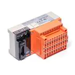


 工商网监
湘ICP备2023018690号
工商网监
湘ICP备2023018690号