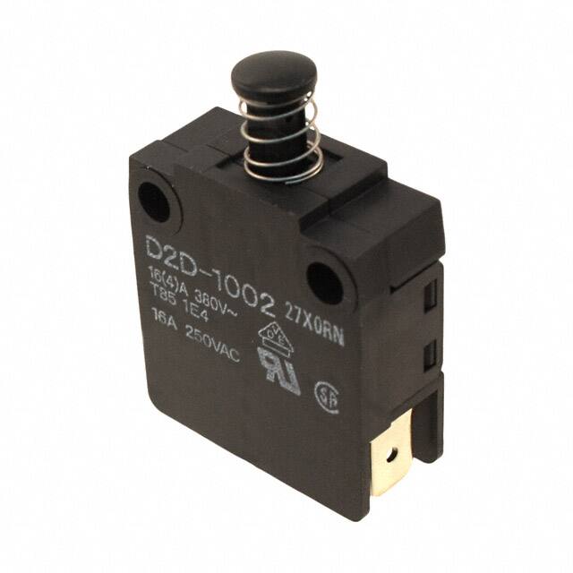
D2D
Power/Door Switch
Door Interlock Power
Switch with Minimum
Contact gap of 3 mm
● Offers the minimum contact gap of 3 mm required
for power switches as standard equipment.
D
2
D
● Safety considerations include a double return spring
and direct drive positive contact opening feature.
● Pull-on lock model for easy maintenance is also
available.
RoHS Compliant
Model Number Legend
Contact Form
●SPST-NO+SPST-NC ●SPST-NO
1 @
2 0@
3
D2D- @
D2D-1000 D2D-2000
D2D-1100 D2D-2100
●SPST-NC
D2D-1001
D2D-1101
D2D-1002
D2D-1102
1. Construction
1: Single pole, contact gap 3 mm
2: Pull-on lock, contact gap 1 mm
3: Double pole, contact gap 3 mm
2. Mounting
0: Screw mounting
1: Panel mounting
NC
NO
NO
NC
NO
NO
NC
NC
●DPST-NO+SPST-NC ●DPST-NO
3. Contact
0: SPST-NO+SPST-NC
1: SPST-NO
2: SPST-NC
3: DPST-NO+SPST-NC
4: DPST-NO
D2D-3103
D2D-3104
List of Models
NO
Mounting
Screw
mounting
Panel
mounting
*
Type
Contact gap
Contact form
Standard
Pull-on lock *
3 mm min.
1 mm
SPST-NO+SPST-NC
D2D-1000
D2D-2000
SPST-NO
D2D-1001
-
SPST-NC
D2D-1002
-
SPST-NO+SPST-NC
D2D-1100
D2D-2100
SPST-NO
D2D-1101
-
SPST-NC
D2D-1102
-
DPST-NO+SPST-NC
D2D-3103
-
DPST-NO
D2D-3104
-
Refer to next page for the pull-on lock function.
NC
NO
NO
NC
NO
NO
NO
NO
NO
Contact Specifications
Item
Type
Standard
Specification
Contact
Inrush
current
Material
Silver
Gap (standard value)
3 mm min.
1 mm
NC
30 A max.
24 A max.
NO
30 A max.
24 A max.
Minimum applicable load
(reference value) *
*
Pull-on lock
Rivet
5 VDC 160mA
Please refer to "●Using Micro Loads" in "■Precautions" for more information on the minimum applicable load.
Ratings
Type
Item
Rated voltage
Resistive load
Standard
250 VAC
16 A
Pull-on lock model
250 VAC
10 A
Note. The above rating values apply under the following test conditions.
(1) Ambient temperature: 20±2°C
(2) Ambient humidity: 65±5%
(3) Operating frequency: 30 operations/min
Terminal Connection Parts (Sold Separately)
Refer to "Basic Switch Common Accessories"
1
�D2D
Power/Door Switch
Characteristics
Item
Model
D2D-1000 models
D2D-2000 models
Permissible operating speed
Permissible Mechanical
operating
Electrical
frequency
300 operations/min
60 operations/min
Insulation resistance
100 MΩ min. (at 500 VDC with insulation tester)
Contact resistance (initial value)
D
2
D
Dielectric
strength
Vibration
resistance
Shock
resistance
Durability *
D2D-3000 models
10 mm to 1 m/s
50 mΩ max.
Between terminals of the same polarity
2,000 VAC 50/60 Hz 1min
1,000 VAC 50/60 Hz 1min
2,000 VAC 50/60 Hz 1min
Between current-carrying metal parts
and ground
2,000 VAC 50/60 Hz 1min
1,500 VAC 50/60 Hz 1min
2,000 VAC 50/60 Hz 1min
Between each terminal and
non-current-carrying metal parts
2,500 VAC 50/60 Hz 1min
1,500 VAC 50/60 Hz 1min
-
Between terminals and actuator
4,000 VAC 50/60 Hz 1min
-
4,000 VAC 50/60 Hz 1min
Malfunction
10 to 55 Hz, 1.5 mm double amplitude
1,000 m/s2 {approx. 100G} max.
Durability
500 m/s2 {approx. 50G} max.
Malfunction
Mechanical
300 m/s2 {approx. 30G} max.
500 m/s2 {approx. 50G} max.
10,000,000 operations min. (60 operations/min)
Electrical
100,000 operations min. (30 operations/min)
Degree of protection
IEC IP40
Degree of protection against electric shock
Class II
Proof tracking index (PTI)
175
Ambient operating temperature
-25 °C to +85 °C (at ambient humidity 60 % max.) (with no icing or condensation)
Ambient operating humidity
85% max. (for +5°C to +35°C)
Weight
Approx. 14 g (for D2D-1000)
Note. The data given above are initial values.
* For testing conditions, consult your OMRON sales representative.
Pull-on lock function (D2D-2000 models)
Direct Contact Opening Mechanism (D2D-1000 models)
When opening or closing the door, the power ON state of the
Switch can be checked with the door left open when applying
normal (momentary) operations. By closing the door after
maintenance inspection, the Switch will resume the normal
momentary operation. (This feature is ideal for conducting the
electrical continuity test, inspection, repair, etc. on the Switch
after its assembly.)
Pushing the plunger
will effectively break the circuit on the
NC side even if a contact weld occurs in the Switch.
Direct Contact Opening Mechanism is
not available in NO connection.
Example
State
Contact
NO-NO
NC-NC
Approved Safety Standard
UL (UL1054) /CSA (CSA C22.2 No.55)
Rated voltage
Model
125 VAC
250 VAC
To turn ON the
power when the
door is closed
ON
OFF
D2D-1000
D2D-2000
D2D-3000
16A
10A
3/4HP
16A 1-1/2HP
D2D-1000
D2D-2000
D2D-3000
16 (4) A
10A
16 (4) A
VDE (EN61058-1)
Rated voltage
Model
250 VAC
Test conditions: 1E4 (10,000 operations) T85 (0°C to 85°C)
Note. The values in parentheses are the motor load ratings.
To turn OFF the
power when the
door is open
OFF
ON
Mounting Holes (Unit: mm)
Screw Mounting Hole
Dimensions
Panel Cutout Dimensions
2-4.3 dia. mounting holes
or M4 screw hole
To turn ON the
power with the
door left open
ON
Four, 1.3R max.
OFF
Pull
13.5±0.1
22±0.1
A
t
Double Spring Mechanism (D2D-1000/3000 models)
Two return springs are provided for the pin plunger. Thus, if
either of the springs is broken, this feature will prevent the Switch
from malfunctioning or short-circuiting.
2
t=1.0 : A=36.7±0.1
t=2.5 : A=37.0±0.1
�D2D
Power/Door Switch
Dimensions (Unit: mm) /Operating Characteristics
Standard model
●Screw Mounting
D2D-1000
D2D-1001
D2D-1002
22±0.1
16
8 dia.
FP
A
Model
13
Operating characteristics
4.3±0.05 dia.
Operating Force
1.8
OP
TTP
OF Max. (NC-OFF)
(NO-ON)
5.8
23.6
Total Travel Force
TTF Max.
Overtravel
OT Min.
33.6
0558RN
Free Position
Operating Position
10.4
25.2
30
●Panel Mounting
D2D-1100
D2D-1101
D2D-1102
4-Quick Connect
Terminal (#250)
6.35±0.1
12.4 1.65+0.1 dia.
0
FP Max.
OP
(NC-OFF)
(NO-ON)
Total Travel Position TTP Max.
D2D
-1000
D2D
-1001
D2D
-1002
2.94 N
{300 gf}
5.88 N
{600 gf}
7.35 N
{750 gf}
5.88 N
{600 gf}
7.35 N
{750 gf}
2.94 N
{300 gf}
7.35 N
{750 gf}
2.3 mm
2.3 mm
5.5 mm
16.4 mm
15.9±0.4 mm
12.7±0.4 mm
10 mm
17 mm
12.7±0.4 mm
10 mm
16.4 mm
15.9±0.4 mm
10 mm
D2D
-1100
D2D
-1101
D2D
-1102
2.94 N
{300 gf}
5.88 N
{600 gf}
7.35 N
{750 gf}
5.88 N
{600 gf}
7.35 N
{750 gf}
2.94 N
{300 gf}
-
2.3 mm
2.3 mm
5.5 mm
12.4 mm
11.9±0.4 mm
8.7±0.4 mm
6 mm
13 mm
8.7±0.4 mm
6 mm
12.4 mm
11.9±0.4 mm
6 mm
40±0.1
8 dia.
21.2
A
Model
Operating characteristics
FP
2.0
OP TTP
Operating Force
OF Max. (NC-OFF)
(NO-ON)
21.8
Total Travel Force
TTF Max.
Overtravel
OT Min.
31.7
Free Position
Operating Position
10.4
25.2
30
●Panel Mounting
D2D-3103
4-Quick Connect
Terminal (#250)
6.35±0.1
12.4 1.65+0.1 dia.
0
FP Max.
OP
(NC-OFF)
(NO-ON)
Total Travel Position TTP Max.
7.35 N
{750 gf}
40±0.4
5.6 dia.
FP
21.2±0.2
A
2
OP TTP
1858RN
3
31
41.5
Model
Operating characteristics
8.8
22.8
31.6
34.4
●Panel Mounting
D2D-3104
6.35±0.1
13
1.65+0.10 dia.
FP
21.2±0.2
A
2
OP TTP
OF Max. (NC-OFF)
(NO-ON)
40±0.4
5.6 dia.
Operating Force
6-Quick Connect
Terminal (#250)
Total Travel Force
TTF Max.
Overtravel
OT Min.
D2D
-3103
D2D
-3104
2.94 N
{300 gf}
5.88 N
{600 gf}
9.81 N
{1,000 gf}
5.88 N
{600 gf}
9.81 N
{1,000 gf}
2.3 mm
2.3 mm
13.5 mm
FP Max.
12.4 mm
OP *
(NC-OFF)
11.9±0.8 mm
(NO-ON)
8.7±0.8 mm
8.7±0.8 mm
Total Travel Position TTP Max.
6.4 mm
6.4 mm
* Operating sequence of the two circuits are not specified.
Free Position
Operating Position
3
31
41.5
8.8
31.6
34.4
4-Quick Connect
Terminal (#250)
6.35±0.1
13
1.65+0.1
0 dia.
Note 1. Unless otherwise specified, a tolerance of ±0.4 mm applies to all dimensions.
2. The operating characteristics are for operation in the A direction ( ).
3
D
2
D
�D2D
Power/Door Switch
Pull-on lock model
●Screw Mounting
D2D-2000
22±0.1
*TTP *OP FP
D
2
D
Momentary Operation (Normal Operation)
16
8 dia.
13
A
Model
4.3±0.05 dia.
Operating characteristics
1.8
OP
TTP
Operating Force
5.8
2948RN
23.6
Total Travel Force
OF Max. (NC-OFF)
(NO-ON)
TTF Max.
Overtravel
OT Min.
33.6
Free Position
Operating Position
10.4
25.2
30
●Panel Mounting
D2D-2100
FP Max.
OP
(NC-OFF)
(NO-ON)
Total Travel Position TTP Max.
6.35±0.1
12.4 1.65+0.1 dia.
4-Quick Connect
0
Terminal (#250)
* In Pull-on lock operation
40±0.1
8 dia.
*TTP *OP FP
OP
Model
Operating characteristics
2.0
TTP
21.8
31.7
10.4
25.2
30
D2D
-2100
1.96 N
{200 gf}
2.94 N
{300 gf}
5.88 N
{600 gf}
1.96 N
{200 gf}
2.94 N
{300 gf}
5.88 N
{600 gf}
4.5 mm
4.5 mm
14.3 mm
13.5±0.6 mm
12.7±0.6 mm
8.3 mm
10.3 mm
9.5±0.6 mm
8.7±0.6 mm
4.3 mm
D2D
-2000
D2D
-2100
Pull-on lock Operation
21.2
A
D2D
-2000
19.61 N
19.61 N
{2,000 gf} {2,000 gf}
Operating Force
OF
Max.
Pretravel
Overtravel
Movement Differential
PT
OT
MD
Max.
Min.
Max.
2 mm
0.4 mm
1.5 mm
2 mm
0.4 mm
1.5 mm
Free Position
Operating Position
Total Travel Position
FP
OP
TTP
Max.
14.3 mm
15.1±0.6 mm
16.5 mm
10.3 mm
11.1±0.6 mm
12.5 mm
Max.
6.35±0.1
4-Quick Connect 12.4 1.65+0.1 dia.
0
Terminal (#250)
* In Pull-on lock operation
Note 1. Unless otherwise specified, a tolerance of ±0.4 mm applies to all dimensions.
2. The operating characteristics are for operation in the A direction ( ).
Precautions
★Please refer to "Basic Switches Common Precautions" for correct use.
●Mounting
• Apply operation force to the pin plunger in the direction it
operates. Applying forces laterally or from an oblique direction
may damage the pin plunger.
• Use M4 mounting screw with plane washers or spring washers
to securely mount the Switch. Tighten the screws to a torque
of 0.49 to 0.69 N·m {5 to 7 kg·cm}.
●Using Micro Loads
Using a model for ordinary loads to open or close the contact of
a micro load circuit may result in faulty contact. It is
recommended to use the Switch in the operation range shown
below. The minimum applicable load is the N-level reference
value. This value indicates the malfunction reference level for the
reliability level of 60% (λ60).
(JIS C5003)
The equation, λ60=0.5×10⁻⁶/operations, indicates that the
1
estimated malfunction rate is less than
operations
2,000,000
with a reliability level of 60%.
Voltage (V)
Correct Use
26 mA
30
24
Operating
range
●Wiring
• It is recommended to use sleeve receptacles when connecting
with the quick connect terminals.
• Insert the receptacle straight toward the terminal.
• Applying excessive external force horizontally or vertically may
cause deformation of terminals and may damage the
housings.
4
12
5
160 mA
0
0.1
1
10
100
1,000
Current (mA)
�D2D
Power/Door Switch
D
2
D
• Application examples provided in this document are for reference only. In actual applications, confirm equipment functions and safety before using the product.
• Consult your OMRON representative before using the product under conditions which are not described in the manual or applying the product to nuclear control systems, railroad
systems, aviation systems, vehicles, combustion systems, medical equipment, amusement machines, safety equipment, and other systems or equipment that may have a serious
influence on lives and property if used improperly. Make sure that the ratings and performance characteristics of the product provide a margin of safety for the system or
equipment, and be sure to provide the system or equipment with double safety mechanisms.
Note: Do not use this document to operate the Unit.
OMRON Corporation
ELECTRONIC AND MECHANICAL COMPONENTS COMPANY
Contact: www.omron.com/ecb
Cat. No. B085-E1-08
0117(0207)(O)
5
�