D2JW
Sealed Subminiature Basic Switch
Ultra-small and Highly Sealed
O Degree of protection conforms to JIS Waterproof
standard and IEC IP67.
(Excluding the terminals on terminal models)
O Wide range of operating temperatures from
−40°C to +85°C.
D
2
J
W
O Gold-alloy crossbar contact and coil spring offer
long durability and high contact reliability.
RoHS Compliant
Model Number Legend
1 @
2 @
3
D2JW-01@
1. Actuator
None : Pin plunger
2. Contact form
1: SPDT
K1A : Short hinge lever
K1 : Hinge lever
2: SPST-NC (Molded lead wire models only)
3: SPST-NO (Molded lead wire models only)
K2 : Hinge roller Lever
K3 : Simulated roller hinge lever
3. Terminals
None : Solder terminals
-MD : Molded lead wires
List of Models
Actuator
Pin plunger
Terminals
Contact form
Solder terminals
SPDT
Molded lead
wires
Solder terminals
Short hinge lever
Molded lead
wires
Molded lead
wires
Molded lead
wires
Molded lead
wires
SPST-NO
D2JW-013-MD
SPDT
D2JW-01K1A1
SPDT
D2JW-01K1A1-MD
SPST-NC
D2JW-01K1A2-MD
D2JW-01K1A3-MD
SPDT
D2JW-01K11
SPDT
D2JW-01K11-MD
SPST-NC
D2JW-01K12-MD
D2JW-01K13-MD
SPDT
D2JW-01K21
SPDT
D2JW-01K21-MD
SPST-NC
D2JW-01K22-MD
SPST-NO
Solder terminals
Simulated Roller Hinge
Lever Models
D2JW-011-MD
D2JW-012-MD
SPST-NO
Solder terminals
Hinge Roller Lever
Models
SPDT
SPST-NC
SPST-NO
Solder terminals
Hinge Lever Models
Model
D2JW-011
D2JW-01K23-MD
SPDT
D2JW-01K31
SPDT
D2JW-01K31-MD
SPST-NC
D2JW-01K32-MD
SPST-NO
D2JW-01K33-MD
Contact form
OSPDT
COM
NO NC
(Black) (Blue) (Red)
OSPST-NC
COM
(Black)
OSPST-NO
NC
(Red)
COM
NO
(Black) (Blue)
The color in parentheses indicates the color of the lead wire.
1
�D2JW
Sealed Subminiature Basic Switch
Contact Specifications
Contact
Characteristics
Specification
Crossbar
Permissible operating speed
Material
Gold alloy
Permissible
operating
frequency
Gap (standard
value)
Inrush current
0.5 mm
D
2
J
W
Mechanical
Electrical
NC
0.1A max.
Insulation resistance
NO
0.1A max.
Contact
resistance
(initial value)
Minimum applicable load (see
note)
5 VDC 1 mA
Dielectric
strength * 1
Ratings
Rated voltage
Resistive load
30 VDC
0.1A
1 mm to 250 mm/s
(for pin plunger models)
240 operations/min
30 operations/min
100 MΩ min.
(at 500 VDC with insulation tester)
Solder terminal models
Molded lead wire models
Mechanical
Durability * 3
Electrical
Solder terminal models
Degree of
protection
140 mΩ max.
Between terminals of the same
polarity
Between current-carrying metal
parts and ground
Between each terminal and
non-current-carrying metal parts
Vibration
Malfunction
resistance * 2
Durability
Shock
resistance
Malfunction * 2
Note. The above rating values apply under the following test conditions.
(1) Ambient temperature: 20±2°C
(2) Ambient humidity: 65±5%
(3) Operating frequency: 30 operations/min
100 mΩ max.
Molded lead wire models
Ambient operating temperature
Ambient operating humidity
Weight
600 VAC 50/60 Hz 1min
1,000 VAC 50/60 Hz 1min
1,000 VAC 50/60 Hz 1min
10 to 55 Hz, 1.5 mm double
amplitude
1,000 m/s2 {approx. 100G} max.
2
200 m/s {approx. 20G} max.
1,000,000 operations min.
(60 operations/min)
100,000 operations min.
(30 operations/min)
IEC IP67 (excluding the terminals
on terminal models)
IEC IP67
−40°C to +85°C (at ambient
humidity of 60% max.)
(with no icing or condensation)
35% to 98% (for +5°C to +35°C)
Approx. 0.6g (for pin plunger
models with terminals)
Note. The data given above are initial values.
*1. The dielectric strength values shown apply for use with Separator (refer
to page 4).
*2. For the pin plunger models, the above values apply for use at the free
position and total travel position. For the lever models, they apply at the
total travel position. Close or open circuit of the contact is 1ms max.
*3. For testing conditions, consult your OMRON sales representative.
Mounting Holes (Unit: mm)
M2.3 mounting screw hole
4.8±0.1
Dimensions (Unit: mm) /Operating Characteristics
Dimensions and operating characteristics of other actuator models for lead wire models are omitted in the illustration below, as the
dimensions other than the termial part and operatiing characteristics is common with Solder terminal models.
OPin plunger models
D2JW-011
1.6 dia.
PT
A
Operating characteristics
Operating Force
Releasing Force
OP
9.4
12.3
Pretravel
PT Max.
Overtravel
OT Min.
Movement Differential MD Max.
2.8
+0.05
2.35−0.025
1.3
1
2
2.5+0.05
−0.025 dia.
OF Max.
RF Min.
0.5
+0.05
2.35−0.025
dia.
0.4
Operating Position
OP
Operating Force
Releasing Force
OF Max.
RF Min.
2.45 N {250 gf}
0.98 N {100 gf}
0.6 mm
0.3 mm
0.1 mm
8.1±0.3 mm
5.3±0.1
4.8±0.05 3.95
3.95 3.95
12.7
OShort hinge lever models
D2JW-01K1A1
1.8
7.95
PT
t0.3 Stainless-steel
A lever
R11.5
OP
3
6.15
Pretravel
PT Max.
Overtravel
OT Min.
Movement Differential MD Max.
9.4
12.3
2.8
+0.05
2.35−0.025
1.3
1
2
2.5+0.05
−0.025 dia.
+0.05
2.35−0.025
dia.
4.8±0.05 3.95
3.95 3.95
12.7
Note 1. Unless otherwise specified, a tolerance of ±0.4 mm applies to all dimensions.
Note 2. The operating characteristics are for operation in the A direction ( ).
2
0.5
0.4
5.3±0.1
Operating Position
OP
1.15 N {117 gf}
0.23 N {23 gf}
5.4 mm
0.7 mm
0.5 mm
8.4±0.8 mm
�D2JW
OHinge lever models
D2JW-01K11
Sealed Subminiature Basic Switch
7.95
1.8
A
PT
t0.3 Stainless-steel
lever
R16.5
3
Operating Force
Releasing Force
OP
6.15
9.4
Pretravel
PT Max.
Overtravel
OT Min.
Movement Differential MD Max.
12.3
2.8
+0.05
2.35−0.025
1.3
1
2
2.5+0.05
−0.025 dia.
+0.05
2.35−0.025
dia.
OF Max.
RF Min.
0.5
0.4
Operating Position
OP
0.80 N {82 gf}
0.15 N {16 gf}
6.4 mm
1.4 mm
0.7 mm
8.4±0.8 mm
D
2
J
W
5.3±0.1
4.8±0.05 3.95
3.95 3.95
12.7
OSimulated roller lever hinge models
D2JW-01K31
PT
1.8
7.95
5.35
R1.3
1.3
1.9
t0.3 Stainless-steel
lever
3
A
Operating Force
Releasing Force
OP
6.15
Pretravel
PT Max.
Overtravel
OT Min.
Movement Differential MD Max.
9.4
12.3
2.8
+0.05
2.35−0.025
1.3
1
2
2.5+0.05
−0.025 dia.
+0.05
2.35−0.025
dia.
OF Max.
RF Min.
0.5
0.4
Operating Position
OP
Operating Force
Releasing Force
OF Max.
RF Min.
0.95 N {97 gf}
0.19 N {20 gf}
5.5 mm
1.1 mm
0.6 mm
10.3±0.8mm
5.3±0.1
4.8±0.05 3.95
3.95 3.95
12.7
OHinge roller lever models
D2JW-01K21
7.95
1.8
PT
4.8×2.2 dia.
Polyacetal resin roller
A
R13.5
OP
6.15
9.4
Pretravel
PT Max.
Overtravel
OT Min.
Movement Differential MD Max.
12.3
2.8
+0.05
2.35−0.025
1.3
1
2
2.5+0.05
−0.025 dia.
+0.05
2.35−0.025
dia.
0.5
0.4
Operating Position
OP
Operating Force
Releasing Force
OF Max.
RF Min.
0.98 N {100 gf}
0.19 N {20 gf}
5.2 mm
1.1 mm
0.5 mm
14.6±0.8 mm
5.3±0.1
4.8±0.05 3.95
3.95 3.95
12.7
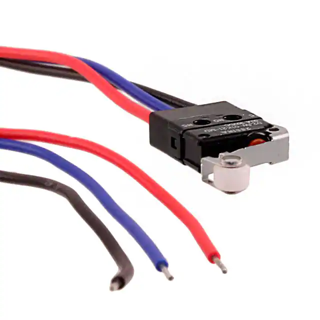
OMolded lead wire models
D2JW-01@@@-MD
1.6 dia.
PT
A
0.05
2.35−+0.025
dia.
2.35+−0.05
0.025
OP
15.3
2.5+−0.05
0.025 dia.
4.8±0.05
3.95
Pretravel
PT Max.
Overtravel
OT Min.
Movement Differential MD Max.
8.7
Operating Position
OP
2.45 N {250 gf}
0.98 N {100 gf}
0.6 mm
0.3 mm
0.1 mm
8.1±0.3 mm
AVS 0.3
300±10
Note. When ordering, replace @ with the code
for the actuator and contact form that
you need.
5±2
COM NO NC
(Black) (Blue) (Red)
12.7
5.3±0.1
Note 1. Unless otherwise specified, a tolerance of ±0.4 mm applies to all dimensions.
Note 2. The operating characteristics are for operation in the A direction ( ).
3
�D2JW
Sealed Subminiature Basic Switch
Precautions
+Please refer to "Basic Switches Common Precautions" for correct use.
Cautions
OTerminal Connection
Correct Use
OMounting
Before soldering the lead wire to the terminal, first insert the lead
wire conductor through the terminal hole.
Complete the soldering at the iron tip temperature till 250°C
within 3 seconds, and do not apply any external force for 1
D minute after soldering. Soldering at an excessively high
2 temperature or soldering for more than 3 seconds may
J
W deteriorate the characteristics of the Switch.
ODegree of Protection
• The Switch was tested and found to meet the conditions
necessary to meet the following standard given below. The
test checks for water intrusion after immersion for a specified
time period, not for switching operation underwater.
JIS C0920:
Degrees of protection provided by enclosures of electrical
apparatus (IP Code)
IEC 60529:
Degrees of protection provided by enclosures (IP Code)
Degree of protection: IP67
(check water intrusion after immersion
for 30 min. submerged 1m
underwater)
Use M2.3 mounting screw with plane washers or spring washers
to securely mount the Switch. Tighten the screws to a torque of
0.20 to 0.29 N·m {2 to 3 kgf·cm}.
OWiring Molded Lead Wire Models
When wiring molded lead wire models, ensure that there is no
weight applied on the wire and that the wire is not bent.
Otherwise, damage to the Switch or deterioration in the sealing
may result.
OUsing Micro Loads
Even when using micro load models within the operating range,
if inrush/surge current occurs, it may increase the contact wear
and so decrease durability. Therefore, insert a contact protection
circuit where necessary.
OProtection Against Chemicals
Prevent the Switch from coming into contact with oil or
chemicals.
Otherwise, damage to or deterioration of Switch materials may
result.
Separator (sold separately)
SEPARATOR FOR D2JW
2-2.4±0.1 dia.
10.4
5.2
4.8±0.1 3.6
12
t=0.18
Note. The material of the separator is EAVTC (epoxy alkyd/varnish tetron cloth).
Please check each region's Terms & Conditions by region website.
OMRON Corporation
Electronic and Mechanical Components Company
Regional Contact
Americas
https://www.components.omron.com/
Asia-Pacific
https://ecb.omron.com.sg/
Korea
https://www.omron-ecb.co.kr/
Europe
http://components.omron.eu/
China
https://www.ecb.omron.com.cn/
Japan
https://www.omron.co.jp/ecb/
© OMRON Corporation 2007-2020 All Rights Reserved.
In the interest of product improvement, specifications are subject to change without notice.
4
Cat. No. B040-E1-06
0220(0207)(O)
�
很抱歉,暂时无法提供与“D2JW-01K21-MD”相匹配的价格&库存,您可以联系我们找货
免费人工找货