D2SW-P
Sealed Subminiature Basic Switch
㧰㧞㧿㨃 㧼-
Sealed Basic Switch with
Simplified Construction,
Mounting Compatible with
SS and D2SW Series.
● Rubber packing construction keeps dust off and
offers temporary waterproofing protection (IEC
IP67).
● Switch rating of 2 A at 250 VAC possible with a
single-leaf movable spring. Models for micro
loads are also available.
● Solder, quick-connect terminals (#110), PCB
terminals, and molded lead wires are available.
● UL, CSA, VDE safety standard approved models
are available upon request.
RoHS Compliant
Model Number Legend
1
D2SW-P@
2 @
3 @
4
@
1. Ratings
2 : 250 VAC 2 A
3. Contact form
None : SPDT
01 : 30 VDC 0.1 A
-2 : SPST-NC (Molded lead wire models only)
-3 : SPST-NO (Molded lead wire models only)
2. Actuator
None : Pin plunger
4. Terminals
L1 : Hinge lever
L2 : Hinge roller lever
H : Solder terminals
D : Self-clinching PCB terminals
L3 : Simulated roller lever
T : Quick-connect terminals (#110)
M : Molded lead wires
List of Models (Contact your dealer for detailed delivery date.)
Ratings
Actuator
Terminals
Pin plunger
SPDT
PCB terminals
SPDT
Molded lead wires
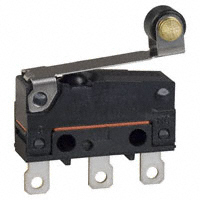
Hinge roller lever
Simulated roller lever
Quick-connect terminals (#110)
PCB terminals
D2SW-P2H
D2SW-P01H
D2SW-P2T
D2SW-P01T
D2SW-P2D
D2SW-P01D
D2SW-P2M
D2SW-P01M
SPST-NC
D2SW-P2-2M
D2SW-P01-2M
SPST-NO
D2SW-P2-3M
D2SW-P01-3M
D2SW-P2L1H
D2SW-P01L1H
D2SW-P2L1T
D2SW-P01L1T
D2SW-P2L1D
D2SW-P01L1D
Solder terminals
Hinge lever
0.1 A
Contact Form
Solder terminals
Quick-connect terminals (#110)
2A
SPDT
Molded lead wires
D2SW-P2L1M
D2SW-P01L1M
Solder terminals
D2SW-P2L2H
D2SW-P01L2H
D2SW-P2L2T
D2SW-P01L2T
D2SW-P2L2D
D2SW-P01L2D
Quick-connect terminals (#110)
PCB terminals
SPDT
Molded lead wires
D2SW-P2L2M
D2SW-P01L2M
Solder terminals
D2SW-P2L3H
D2SW-P01L3H
D2SW-P2L3T
D2SW-P01L3T
D2SW-P2L3D
D2SW-P01L3D
D2SW-P2L3M
D2SW-P01L3M
Quick-connect terminals (#110)
PCB terminals
SPDT
Molded lead wires
Separator (Sold Separately), Terminal Connector (Sold Separately)
Refer to "Micro Switch Common Accessories"
1
�D2SW-P
Sealed Subminiature Basic Switch
Contact Form
●SPDT
● SPST-NC (Molded lead wire models
only)
㧰㧞㧿㨃 㧼-
COM NO NC
(Black) (Blue) (Red)
COM
(Black)
NC
(Red)
Contact Specifications
Item
Model
D2SW-P01 models
Rivet
Crossbar
Silver
Gold alloy
Contact Material
Gap (Standard value)
Minimum applicable load
(reference value)*
*
COM
NO
(Black) (Blue)
The color in parentheses
indicates the color of the
lead wire.
Ratings
D2SW-P2 models
Specification
● SPST-NO (Molded lead wire
models only)
Model
Resistive load
250 VAC
D2SW-P2 models
0.5 mm
160 mA at 5 VDC
Rated voltage
2A
30 VDC
125 VAC
D2SW-P01 models
0.1 A
30 VDC
1 mA at 5 VDC
Note. The above rating values apply under the following test conditions.
(1) Ambient temperature: 20±2°C
(2) Ambient humidity: 65±5%
(3) Operating frequency: 20 operations/min
Please refer to "●Using Micro Loads" in "Precautions" for more
information on the minimum applicable load.
Approved Safety Standards
The items shown in the "List of Models" are not standard approved models.
Consult your OMRON sales representative for specific models with standard approvals.
UL (UL1054/CSA C22.2 No.55)
Rated voltage
Model
VDE (EN61058-1)
D2SW-P2
D2SW-P01
D2SW-P2
D2SW-P01
125 VAC
250 VAC
2A
0.1 A
-
Rated voltage
125 VAC
250 VAC
Model
2A
0.1 A
-
30 VDC
2A
0.1 A
30 VDC
2A
0.1 A
Testing conditions: 5E4 (50,000 operations) T55 (0°C to 55°C)
Characteristics
Item
Model
Permissible operating speed
Permissible operating
frequency
Dielectric strength *1
Vibration resistance *2
Shock resistance
Durability *3
Degree of protection
120 operations/min
Electrical
30 operations/min
100 mΩ min. (500 VDC with insulation tester)
Terminal models
50 mΩ max.
100 mΩ max.
Molded lead wire models
100 mΩ max.
150 mΩ max.
Between terminals of the
same polarity
1,000 VAC 50/60 Hz for 1 min
600 VAC 50/60 Hz for 1 min
Between current-carrying
metal parts and ground
1,500 VAC 50/60 Hz for 1 min
Between each terminals
and non-current-carrying
metal parts
1,500 VAC 50/60 Hz for 1 min
Malfunction
10 to 55 Hz, 1.5-mm double amplitude
Destruction
1,000 m/s2 {approx. 100G} max.
Malfunction *2
Mechanical
Electrical
Terminal models
Molded lead wire models
Degree of protection against electric shock
Proof tracking index (PTI)
Ambient operating temperature
Ambient operating humidity
Weight
D2SW-P01 models
0.1 mm to 500 mm/s (for pin plunger models)
Mechanical
Insulation resistance
Contact resistance
(initial value)
D2SW-P2 models
300 m/s2 {approx. 30G} max.
1,000,000 operations min. (60 operations/min)
50,000 operations min. (20 operations/min)
200,000 operations min. (20 operations/min)
IEC IP67 (excluding the terminals on terminal models)
IEC IP67
Class I
250
-20°C to +70°C (at ambient humidity of 60% max.) (with no icing or condensation)
85% max. (for +5 to +35°C)
Approx. 2 g (for pin plunger models with terminals)
Note. The data given above are initial values.
*1. The dielectric strength shown in the table indicates values for models with a Separator.
*2. The values are at Free Position and Total Travel Position values for pin plunger, and Total Travel Position value for lever. Close or open circuit of contact is 1 ms
max.
*3. For testing conditions, consult your OMRON sales representative.
2
�D2SW-P
Sealed Subminiature Basic Switch
Terminals and Shapes (Unit: mm)
●Solder terminals
●Quick-connect terminals (#110)
C
C
NC
NC
NC
NC
7.3
2.15
3.3±0.1
3.3±0.1
11
3-1.6 dia. holes
3.2
8.55
7.1
0.5
0.5
3-2.8
6.4±0.2
7.6±0.2 7.6±0.2
15.5
㧰㧞㧿㨃 㧼-
6.4±0.2
5.15 9.5±0.1
19.8±0.2
5.15 9.5±0.1
19.8±0.2
●Molded lead wires
●PCB terminals
C
C
NC
NC
NC
1.8
NC
3.3±0.1
9.2
3.9
1.85
3-1.2
3-0.8
8.8±0.2
COM (Black)
(AWG22, UL1007)
1.3
6.4±0.2
0.5
16.1±0.2
300±10
6.4±0.2
5.15 9.5±0.1
19.8±0.2
NC (Red)
(AWG22, UL1007)
(5)
16.1±0.1
8.8±0.1
3-1.35∼1.5 dia.
0.7
5.15 9.5±0.1
NO (Blue)
(AWG22, UL1007)
21.2
Mounting Holes (Unit: mm)
2-M2.3 screw holes
9.5±0.1
3
�D2SW-P
Sealed Subminiature Basic Switch
Dimensions (Unit: mm) / Operating Characteristics
The illustrations and drawings are for solder terminal models.
Refer to "Terminals and Shapes" of previous page for details on models with quick-connect terminals (#110) or PCB terminals or molded lead wires.
The @ in the model number is for the contact form code or the terminal code. See the "List of Models" for available combinations of models.
●Pin Plunger Models
D2SW-P2@@
D2SW-P01@@
A
7.55±0.2
PT
2.5±0.07
1.8 dia. 2.35 +0.075
-0.05 dia.
dia.
Model
D2SW-P2@@
D2SW-P01@@
Operating characteristics
OP
㧰㧞㧿㨃 㧼-
C
NC
6.9 7.7
NC
3.3±0.1
2.35 +0.075
-0.05
7.3
3.2
2.15
3-1.6 dia. holes
8.55
15.5
0.5
6.4±0.2
Operating Force
Releasing Force
OF
RF
Max.
Min.
1.8 N {184 gf}
0.2 N {20 gf}
Pretravel
Overtravel
Movement Differential
PT
OT
MD
Max.
Min.
Max.
0.6 mm
0.4 mm
0.15 mm
Operating Position
OP
8.4±0.3mm
5.15 9.5±0.1
19.8±0.2
●Hinge Lever Models
D2SW-P2L1@@
D2SW-P01L@@
A
t=0.3 Stainless-steel lever
14.5±0.6
2.35 +0.075
-0.05 dia.
2.5±0.07 dia.
C
2.35 +0.075
-0.05
D2SW-P2L1@@
D2SW-P01L1@@
NC
OF
RF
Max.
Min.
0.6 N {61 gf}
0.05 N {5 gf}
Overtravel
OT
Movement Differential MD
Min.
Max.
0.8 mm
0.8 mm
Free Position
Operating Position
Max.
13.6 mm
8.8±0.8 mm
Operating Force
Releasing Force
OP FP
6.9 7.7
NC
3.3±0.1
7.3
3.2
2.15
3-1.6 dia. holes
8.55
15.5
5.15 9.5±0.1
19.8±0.2
●Hinge Roller Lever Models
D2SW-P2L2@@
D2SW-P01L2@@
0.5
4.8x3.2 dia.
Polyacetal resin roller
14.5±0.6
0.075
2.35 +0.075
-0.05 dia.
2.5±0.07 dia.
Operating characteristics
OP FP
C
2.35 +0.075
-0.05
NC
6.9 7.7
NC
3.3±0.1
7.3
3.2
2.15
3-1.6 dia. holes
8.55
15.5
5.15 9.5±0.1
19.8±0.2
●Simulated Roller Lever Models
D2SW-P2L3@@
D2SW-P01L3@@
t=0.3 Stainless-steel lever
0.5
Model D2SW-P2L2@@
D2SW-P01L2@@
Operating Force
Releasing Force
OF
RF
Max.
Min.
0.6 N {61 gf}
0.05 N {5 gf}
Overtravel
Movement Differential
OT
MD
Min.
Max.
0.8 mm
0.8 mm
Free Position
Operating Position
FP
OP
Max.
19.3 mm
14.5±0.8 mm
Model
D2SW-P2L3@@
D2SW-P01L3@@
6.4±0.2
A
R1.3
2.35 +0.075
-0.05 dia.
15.8±0.6
2.5±0.07 dia.
Operating characteristics
C
2.35 +0.075
-0.05
FP
OP
6.4±0.2
A
t=0.3 Stainless-steel lever
NC
6.9 7.7
OP FP
Operating Force
Releasing Force
OF
RF
Max.
Min.
0.6 N {61 gf}
0.05 N {5 gf}
Overtravel
Movement Differential
OT
MD
Min.
Max.
0.8 mm
0.8 mm
Free Position
Operating Position
FP
OP
Max.
15.5 mm
10.7±0.8 mm
NC
3.3±0.1
7.3
3.2
2.15
8.55
15.5
5.15 9.5±0.1
19.8±0.2
3-1.6 dia. holes
Note 1. Unless otherwise specified, a tolerance of ±0.4 mm applies to all dimensions.
Note 2. The operating characteristics are for operation in the A direction ( ).
4
Model
Operating characteristics
0.5
6.4±0.2
�D2SW-P
Sealed Subminiature Basic Switch
Precautions
★ Please refer to "Basic Switches Common Precautions" for correct use.
●Side-actuated (Cam/Dog) Operation
Cautions
●Degree of Protection
Correct Use
●Mounting
• Turn OFF the power supply before mounting or removing the
Switch, wiring, or performing maintenance or inspection.
Failure to do so may result in electric shock or burning.
• Use M2.3 mounting screws with plane washers or spring
washers to securely mount the Switch.
Tighten the screws to a torque of 0.23 to 0.26 N·m {2.3 to
2.7 kgf·cm}. Exceeding the specified torque may result in
deterioration of the sealing or damage.
●Operating Body
• Use an operating body with low frictional resistance and of a
shape that will not interfere with the sealing rubber, otherwise
the plunger may be damaged or the sealing may deteriorate.
With the pin plunger models, set the Switch so that the plunger
can be pushed in from directly above. Since the plunger is
covered with a rubber cap, applying a force from lateral
directions may cause damage to the plunger or reduction in
the sealing capability. Since the plunger is covered with a
rubber cap, applying a force from lateral directions may cause
damage to the plunger or reduction in the sealing capability.
●Soldering
• Connecting to Solder Terminals
When soldering the lead wire to the terminal, first insert the
lead wire conductor through the terminal hole and then
conduct soldering.
Complete the soldering at the iron tip temperature between
350 to 400°C within 3 seconds, and do not apply any external
force for 1 minute after soldering. Soldering at a excessively
high temperature or soldering for more than 3 s may
deteriorate the characteristics of the Switch.
• Connecting to Quick-connect Terminals
Wire the quick-connect terminals (#110) with receptacles.
Insert the terminals straight into the receptacles. Applying
excessive external force laterally may cause deformation of
terminals and may damage the housings.
• Connecting to PCB terminals
When using automatic soldering baths, we recommend
soldering at 260±5°C within 5 seconds. Make sure that the
liquid surface of the solder does not flow over the edge of the
board.
When soldering terminals manually, complete the soldering at
the iron tip temperature between 350 to 400°C within 3
seconds, and do not apply any external force for 1 minute after
soldering. When applying solder, keep the solder away from
the case of the Switch and do not allow solder or flux to flow
into the case.
●Handling
• Do not handle the Switch in a way that may cause damage to
the sealing rubber.
• When handling the Switch, ensure that uneven pressure or, as
shown in the following diagram, pressure in a direction other
than the operating direction is not applied to the Actuator,
otherwise the Actuator or Switch may be damaged, or
durability may be decreased.
●Wiring Molded Lead Wire Models
• When wiring molded lead wire models, ensure that there is no
force applied on the wire or that there are no sharp bends near
the parts where the wire is drawn out.
Otherwise, damage to the Switch or deterioration in the
sealing may result.
5
㧰㧞㧿㨃 㧼-
• Do not use this product in water.
Although this models satisfy the test conditions for the
standard given below, this test is to check the ingress of water
into the switch enclosure after submerging the Switch in water
for a given time. Satisfying this test condition does not mean
that the Switch can be used in water.
JIS C0920:
Degrees of protection provided by enclosures of electrical
apparatus (IP Code)
IEC 60529:
Degrees of protection provided by enclosures (IP Code)
Degree of protection: IP67
(check water intrusion after immersion
for 30 min submerged 1 m
underwater)
• Do not operate the Switch when it is exposed to water spray,
or when water drops adhere to the Switch surface, or during
sudden temperature changes, otherwise water may intrude
into the interior of the Switch due to a suction effect.
• Prevent the Switch from coming into contact with oil and
chemicals.
Otherwise, damage to or deterioration of Switch materials may
result.
• Do not use the Switch in areas where it is exposed to silicon
adhesives, oil, or grease, otherwise faulty contact may result
due to the generation of silicon oxide.
• The environment-resistant performance of the switch differs
depending on operating loads, ambient atmospheres, and
installation conditions, etc. Please perform an operating test of
the switch in advance under actual usage conditions.
• When using a cam or dog to operate the Switch, factors such
as the operating speed, operating frequency, push-button
indentation, and material and shape of the cam or dog will
affect the durability of the Switch. Confirm performance
specifications under actual operation conditions before using
the Switch in applications.
�D2SW-P
Sealed Subminiature Basic Switch
●Using Micro Loads
Voltage (V)
㧰㧞㧿㨃 㧼-
• Using a model for ordinary loads to open or close the contact
of a micro load circuit may result in faulty contact. Use models
that operate in the following range. However, even when using
micro load models within the following operating range, if
inrush current occurs when the contact is opened or closed, it
may increase the contact wear and so decrease durability.
Therefore, insert a contact protection circuit where necessary.
The N-level reference value applies for the minimum
applicable load.This value indicates the malfunction reference
level for the reliability level of 60% (λ60). (JIS C5003)
The equation λ60=0.5×10⁻⁶/operations indicates that the
1
estimated malfunction rate is less than 2,000,000 operations
with a reliability level of 60%.
30
0.16 mA
26 mA
100 mA
24
Operating range for
micro load models
D2SW-P01
Operating
range for
general-load
models
D2SW-P2
12
5
1 mA
100 mA 160 mA
0
0.1
1
10
100
1,000
Current (mA)
• Application examples provided in this document are for reference only. In actual applications, confirm equipment functions and safety before using the product.
• Consult your OMRON representative before using the product under conditions which are not described in the manual or applying the product to nuclear control systems, railroad
systems, aviation systems, vehicles, combustion systems, medical equipment, amusement machines, safety equipment, and other systems or equipment that may have a serious
influence on lives and property if used improperly. Make sure that the ratings and performance characteristics of the product provide a margin of safety for the system or
equipment, and be sure to provide the system or equipment with double safety mechanisms.
Note: Do not use this document to operate the Unit.
OMRON Corporation
ELECTRONIC AND MECHANICAL COMPONENTS COMPANY
6
Contact: www.omron.com/ecb
Cat. No. B109-E1-04
0812(0207)(O)
�