�
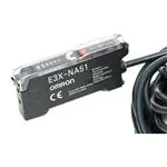
Digital Fiber Amplifier
E3X-DA
Digital Fiber Amplifier Provides High
Performance and Ease of Use
� First amplifier to offer three
user-selectable displays: digital level,
percentage and analog display
� Flashing LED and digital display of light
intensity simplifies optical axis alignment
� Reverse mode sets the digital display to
read right-side-up regardless of
amplifier orientation
� Adjustable off-delay timer (0 to 200 ms)
� Three setting modes let users choose
the ratio of response speed to sensing
distance: standard sensing distance
(400 mm), long sensing distance
(500 mm) and high speed (250 �s)
� 12-bit A/D converter ensures high
resolution for precise detection and
differentiation
� Choose digital or dual analog/digital
output models with NPN or PNP output
Ordering Information
� AMPLIFIER UNITS
Item
Standard models
Monitor-output models
Appearance
Part number
Connections
Output
NPN output
PNP output
Pre-leaded
ON/OFF output
E3X-DA11
E3X-DA41
ON/OFF output
Analog output
E3X-DA21
E3X-DA51
�E3X-DA
E3X-DA
Specifications
� RATINGS/CHARACTERISTICS
Amplifier Unit
Part number
E3X-DA11
E3X-DA41
E3X-DA21
E3X-DA51
NPN output
PNP output
NPN output
PNP output
NPN open collector
Load current:
50 mA max.
Residual voltage:
1 V max.
PNP open collector
Load current:
50 mA max.
Residual voltage:
2 V max.
Supply voltage
12 to 24 VDC ± 10%, ripple (p-p) 10% max.
Current consumption
75 mA max.
Light source (wavelength)
Red LED (660 nm)
Required fiber optic cables
All E32 series
Control output
ON/OFF output
NPN open collector
Load current:
50 mA max.
Residual voltage:
1 V max.
Monitor output
----------------------------------------------------------
Switch selectable
Light ON/Dark ON operation
Operation mode
PNP open collector
Load current:
50 mA max.
Residual voltage:
2 V max.
Load 1 to 5 VDC, 10 kΩ min. Load resistance
10 kΩ min.
Circuit protection
Reverse polarity, output short-circuit, mutual interference protection
Response time
High-speed mode: 250 �s for operation and reset
Standard mode: 1 ms for operation and reset
Long-distance mode: 4 ms for operation and reset
Sensitivity setting
Teaching or manual method
Timer function
OFF-delay timer, range: 0 to 200 ms (5 ms increment)
Indicators
7 segment digital incident level display: RED
7 segment digital incident percentage level display: RED
7 segment digital threshold display: RED
2 color indication bar for threshold and excess gain: GREEN and RED
Operation indicator: ORANGE
Display timing
Switch selectable
Normal/peak-hold/bottom-hold
Display
orientation
Switch selectable
Normal/reverse
Optical axis adjustment
Optical axis adjustment possible (flashing function)
Ambient illumination
Illumination intensity at light-intercepting surface:
Incandescent lamp: 3,000 lx max.; Sunlight: 10,000 lx max.
Ambient
t
temperature
t
Operating
–25°C to 55°C (–13°F to 131°F) with no icing or condensation
Storage
–30�C to 70 (–22°F to 158°F) with no icing or condensation
Ambient humidity
Operating and storage: 35% to 85% (with no condensation)
Insulation resistance
20 MΩ min. (at 500 VDC)
Dielectric strength
1,000 VAC at 50/60 Hz for 1 minute
Vibration resistance
10 to 55 Hz with a 1.5-mm double amplitude or 300 m/s2 for 2 hrs each in X, Y and Z axes
Shock resistance
500 m/s2: 3 times each in X, Y and Z axes
Degree of protection
IEC60529 IP50 (when protective cover is attached)
Connections
3 conductor cable, 2 m (6.5ft)
Prewired
Weight (packed state)
Approx. 100 g
Material
Case
PBT
Cover
Polycarbonate
Accessories
2
Mounting bracket, instruction sheet
4 conductor cable, 2 m (6.5ft)
�E3X-DA
E3X-DA
Nomenclature
� DIGITAL FIBER-OPTIC AMPLIFIER
Lock Button
Level Display
Setting Buttons
TEACH
MODE
Operation Indicator (orange)
Operation Mode Selector
ON when output is ON.
Selectable between Light-ON and Dark-ON modes.
OFF when output is OFF.
Mode Selector
Selectable among SET, ADJ, and RUN modes.
� DISPLAY AND SPECIAL FUNCTION SETTINGS
Display Setting
The E3X-DA offers three display modes, which are Digital Incident Level display, Digital Percent display and Analog display.
•
•
•
Digital Incident Level Display: the incident level is digitally displayed.
Digital Percent Display: the threshold-based excess gain is displayed in percentage.
Analog Display: threshold and excess gain is displayed by two-color (red and green) bar graph.
Special Function Setting
The E3X-DA series has various functions that give users more flexibility in meeting a variety of application requirements.
•
•
•
•
•
Sensing Function: Enables users to choose either standard sensing distance mode (400 mm), long sensing distance mode
(500 mm) or high speed mode (response time = 250 �s)
Timer Function: Enables users to select various OFF-delay timer settings from (0 to 200 ms). OFF-delay timer lengthens the duration of a short, high-speed signal so that it can be recognized as input to Programmable Controllers during a scan cycle.
Flashing Function: Flashing red LED allows easier optical axis adjustment.
Display Hold Setting: This function provides easy data reading during optical axis adjustment and high-speed detection by holding
the displayed value for a period of time. Displayed data gets updated every 2 seconds. Within the 2-second timeframe, the maximum
or minimum value is displayed (data will be flashing).
Display Orientation Setting: Reversible digital display provides easy data reading from any mounting orientation.
3
�E3X-DA
E3X-DA
Operation
� OUTPUT CIRCUITS
Output
Part
number
Mode
selector
State of
output
transistor
NPN
E3X-DA11
LIGHT
ON
(L/ON)
Light ON
Output circuit
Timing chart
Incident received
Operation indicator (orange)
Interrupted
Brown
Display
Operation indicator ON
(orange)
OFF
Load
Black
Control output
Photoelectric
Sensor
main
circuit
Output
transistor
12 to
24 VDC
Load (relay)
Dark ON
ON
OFF
Operate
Release
(Between brown and black)
Blue
DARK
ON
(D/ON)
T
Incident
Interrupted
Operation indicator ON
(orange)
OFF
Output
transistor
Load (relay)
T
ON
OFF
Operate
Release
(Between brown and black)
E3X-DA21
LIGHT
ON
(L/ON)
Light ON
Incident
Operation indicator (orange)
Interrupted
Brown
Display
Black
Photoelectric
Sensor
main
circuit
Control output
47Ω
Orange
Monitor
output
1 to 5 V Load
12 to
24 VDC
Output
transistor
Load (relay)
T
ON
OFF
Operate
Release
(Between brown and black)
*
Blue
DARK
ON
(D/ON)
Operation indicator ON
(orange)
OFF
Load
Dark ON
Incident
Interrupted
T
Operation indicator ON
(orange)
OFF
*Load resistance: 10 kΩ min.
Output
transistor
Load (relay)
ON
OFF
Operate
Release
(Between brown and black)
PNP
E3X-DA41
LIGHT
ON
(L/ON)
Incident
Light ON
Operation indicator (orange)
Interrupted
Brown
Display
Photoelectric
Sensor
main
circuit
Control output
Black
Operation indicator
(orange)
12 to
24 VDC Output
transistor
Load
Load (relay)
Dark ON
T
OFF
ON
OFF
Operate
Release
(Between blue and black)
Blue
DARK
ON
(D/ON)
ON
Incident
Interrupted
Operation indicator ON
(orange)
OFF
Output
transistor
Load (relay)
T
ON
OFF
Operate
Release
(Between blue and black)
4
�E3X-DA
E3X-DA
Output
Part
number
Mode
selector
State of
output
transistor
PNP
E3X-DA51
LIGHT
ON
(L/ON)
Light ON
Output circuit
Timing chart
Incident
Operation indicator (orange)
Interrupted
Brown
Operation indicator ON
(orange)
OFF
Display
Photoelectric
Sensor
main
circuit
Control output
Black
47Ω
Monitor output
1 to 5 V
12 to
24 VDC Output
transistor
Load
Load (relay)
*
DARK
ON
(D/ON)
Dark ON
ON
OFF
Operate
Release
(Between blue and black)
Orange
Blue
Load
Incident
Interrupted
*Load resistance: 10 kΩ min.
T
Operation indicator ON
(orange)
OFF
Output
transistor
Load (relay)
T
ON
OFF
Operate
Release
(Between blue and black)
5
�E3X-DA
E3X-DA
� CHOOSING THE RIGHT TEACHING METHOD
Refer to the following to select the most suitable sensitivity setting method.
Using the Sensor at the Maximum
Sensitivity
Sensing Slight Differences
Sensitivity Setting Without
Objects
Application Examples
Application Examples
Application Examples
•
•
•
•
•
•
•
Sensitivity Setting
•
Detection of a large passing object
with through-beam fibers
Sensing applications with no background
Detection of transparent objects
Color discrimination
Detection of delicate level difference
Detecting IC Chips on Film Sheet
Checking IO Tray Arrangements
Detection of minute passing objects
Detection of lead wires
High-precision positioning
Detecting Lead Frame Position
E3X-DA
E32-T16P
E3X-DA
Film Sheet
Lead Frame
E32-D32
Maximum Sensitivity Setting
Two-point Teach Mode
Sensitivity Adjustment (Fine-tuning)
Fine-tuning on Production Lines
Reason
• Marginal sensitivity adjustments is
required considering the differences
in targets
• For high-precision positioning of
electronic parts
Detecting
Lead Frame Rises
Detecting
Cassette Tape Cases
Ensuring reliable detection without
being influenced by the difference in
color or mark.
E32-T24
E3X-DA
E3X-DA
E32-L25A
3.3 mm
One-point Teach Mode (Positioning)
6
One-point Teach Mode
�E3X-DA
E3X-DA
� SENSITIVITY SETTING (TEACHING)
� TWO-POINT TEACH MODE
Set the mode selector to “SET” to start teaching. The red level
display will flash if teaching error occurs. In this case, repeat the
entire teaching procedure. The E3X-DA has the following four
teaching modes.
1. Set the mode selector to “SET”.
Maximum Sensitivity Setting
2. Press the “TEACH” button for approximately 1 second when
the object is at the sensing position.
1. Set the mode selector to “SET”.
2. Press the “TEACH” button for 3 seconds (min).
Object
3. Teaching is complete when the level display changes from
red to green. Digital incident level will appear shortly after the
display changes from red to green.
3. The red level display is lit.
(Red)
(Green)
(Red)
4. Remove the object from the sensing area, and press the
“TEACH” button for approximately 1 second.
1234
4. Set to “RUN” mode.
� ONE-POINT TEACH MODE
(WITHOUT OBJECT)
1. Set the mode selector to “SET”.
5. Teaching is complete when the green level display is lit.
Digital incident level will appear shortly after the green display is lit.
(Green)
2. Press the “TEACH” button for approximately 1 second.
1234
6. Set to “RUN” mode.
3. Teaching is complete when the red level display is lit.
Digital incident level will appear shortly after the red level
display is lit.
(Red)
1234
4. Set to “RUN” mode.
5. The threshold is automatically set.
Note: Try the two-point teaching mode if the difference in level is
too fine.
7
�E3X-DA
E3X-DA
� ONE-POINT TEACH MODE
(POSITIONING)
1. First set to “One-point Teach Mode (without object)”.
2. Set the sensor to “ADJ” mode.
3. While in the “ADJ” mode, adjust the threshold by pressing the
“TEACH” button until the operation indicator is lit. Pressing
the “TEACH” button increases the sensitivity, but lowers the
threshold level. Pressing the “MODE” button decreases the
sensitivity, but increases the threshold level.
� SPECIAL FUNCTION SETTING
E3X-DA series has various functions that give users more
flexibility in solving a variety of application requirements such as
the following:
•
•
•
•
•
•
Long sensing distance (Sensing Function)
Faster response time (Sensing Function)
Off-delay timer (Timer Function)
Optical axis alignment (Flashing Function)
Digital data display hold setting (Display Hold Setting)
Data display orientation (Display Orientation Setting)
Sensing Function
1. Set the mode selector to “SET”.
Mode
selector
Object
2. Press the “MODE” button until “fs t” is displayed. The “Standard” sensing function (fs t) is the default setting. The
“Standard” sensing function provides the standard detecting
distance (400 mm). Response time is 1 ms.
Output
4. Set to “RUN” mode.
� DISPLAY SETTING
E3X-DA can be programmed to display digital incident level,
digital percent level or analog display.
3. Press the “TEACH” button to obtain the “Long Distance”
sensing function. “F Ld” should appear on the display. The
“Long Distance” function provides a sensing distance that is
about 1.3 times that of the “Standard” detecting distance
(diffuse fiber in use). The “Long Distance” setting has a response time of 4 ms.
1. Set the mode selector to “RUN”. Digital incident level should
appear in the display.
Mode selector
Factory-set to RUN
2. Press the “MODE” button until “123P” is displayed. Digital
percent level is now displayed.
4. Press the “TEACH” button to obtain the “High Speed” sensing function. “F HS” Should appear on the display. The “High
Speed” function provides a detection distance that is about
one-third of the standard distance (diffuse fiber in use). Response time is 0.25 ms.
Digital percent
5. Press the “TEACH” button to return to the “Standard” sensing
function display.
3. Press the “MODE” button to activate the “Analog Incident
Level” display. Two color (red and green) bar graph should
appear in the display.
Analog incident level and threshold
4. Press the “MODE” button to return to the “Digital Incident
Level” display.
8
�E3X-DA
E3X-DA
Timer Function
1. Set the mode selection to “SET”.
4. Press the “TEACH” button to activate “Bottom Hold” display.
Displayed data gets updated every 2 seconds. The minimum
value is displayed.
Mode
Selector
Bottom
2. Press the “MODE” button until “t––0” is displayed. “t––0 is the
default setting.
5. Press the “TEACH” button to return to the default setting.
“HOFF”.
Off
0 (Factory-set)
3. Press the “TEACH” button to set to the desired time setting
(5 ms increment).
Adjustable in
5-ms units
Display Orientation Setting Function
1. Set the mode selector to “SET”.
Mode
Selector
200
Flashing Function
2. Press the “MODE” button until “d123” is displayed. “d123 is
the standard setting.
1. Set the mode selector to “SET”.
Standard (Factory-set)
Mode
Selector
3. Press the “TEACH” button to change the orientation of the
display. “d321 should now appear in the display.
2. Press the “MODE” button until “LOFF” is displayed. “LOFF is
the default setting.
Off (Factory-set)
4. Press the “TEACH” button to return to the standard setting,
“d123”.
3. Press the “TEACH” button to activate the “flashing” function.
Display should read “L On”
4. Press the “TEACH” button to return to the “LOFF” mode.
Display Hold Setting Function
1. Set the mode to “SET”.
Mode
Selector
2. Press the “MODE” button until “HOFF” is displayed. “HOFF is
the default setting.
Off (Factory-set)
3. Press the “TEACH” button to activate “Peak Hold” display.
Displayed data get updated every 2 seconds. The maximum
value is displayed.
Peak
9
�E3X-DA
E3X-DA
Dimensions
Unit: mm (inch)
� AMPLIFIER
E3X-DA�1
Operation indicator
(orange)
Incident level display
Threshold level display
The mounting bracket can be attached to this side.
8
10
(0.39)
61
(2.40)
6
Two, 2.4 mm-dia.
Mounting
Holes
3.3
(0.13)
Two, M3
16
32.5
(1.28)
8
10.75
10.7
4.1
22.4
13
Two, 3.2-mm-dia. holes
3.4
22.4
2.4
16
34.8
4
Mounting bracket
SUS304 stainless steel
4 mm-dia. vinyl-insulated
round cable with 3/4 conductors (40/0.12 mm-dia)
Standard length: 2 m
4.4
16
Two, mounting holes
Installation
� CONNECTION
Connection with S3D2 Sensor Controller
Blue
Black
IN1
Brown
Power
supply
voltage
Output
Functions
Part
number
100 to
240 VAC
Relay
AND, OR
S3D2-AK
AND, OR, and timer
S3D2-CK
Flip-flop
S3D2-BK
Transistor AND, OR, and timer
S3D2-CC
Relay
2 inputs, 2 outputs,
S3D2-DK
2 inputs, 2 outputs, and
timer
S3D2-EK
AND, OR
S3D2-AKD
AND, OR, and timer
S3D2-CKD
+12 V
24 VDC
Note: A maximum of two Sensors can be connected.
10
�E3X-DA
E3X-DA
Connection with K3NX-VD2� Process Meter
*
K3NX-VD2�
Monitor
output Orange
+V
Brown Black
10
11
12
13
14
15
12 VDC 80 mA*
16
17
12 to 24 VDC
0 V Blue
1
2
3
4
5
6
E3X-DA21/51
7
8
9
Use this service power supply for the Sensor with
reference to the power consumption of each Sensor.
Note: 1. Various I/O Units are available for the K3NX.
Select an appropriate output type depending on
the application.
2. For details about the K3NX, refer to the K3NX
Data Sheet in Omron’s Digital Panel Meters
catalog.
3. This wiring is for the K3NX with DC power supply specifications and the Monitor (Analog) Sensor with DC power supply specifications. Check
respective power supply specifications before
wiring them.
� MOUNTING
Mounting
Removal
1. Mount the front part on the mounting bracket (sold together)
or on a DIN rail. (See below.)
2. Press the back part onto the mounting bracket or onto the
DIN rail.
By pulling back the lock (yellow) on the bottom with a flat blade
screwdriver, the amplifier can be removed easily.
In the case of side mounting, attach the mounting bracket on the
amplifier first, and secure the amplifier with M3 screws and
washers. The diameter of the washers should be no more than
6 mm.
(2)
(1)
DIN rail
Washers
(6-mm dia. max.)
11
�E3X-DA
E3X-DA
� FIBER UNIT
Mounting
Use a proper-sized wrench.
Tightening Force
The tightening force applied to the sensing head should be as
follows:
Threaded Model
Spring mounting clip
Toothed washers
Fiber Connection and Disconnection
The E3X amplifier has a lock button. Connect or disconnect the
fibers to or from the E3X amplifier using the following procedures:
1. Connection
Remove the protective cover, insert the fiber into the amplifier,
and lower the lock button until a click is heard.
Nuts
(attachment)
Lock button
Unthreaded Model
Fiber insertion mark
Set screw (M 3 max.)
Fiber
After cutting the fiber using the E39-F4 Fiber Cutter, put an
insertion mark on the fiber as a guide for correct insertion into the
amplifier, and then insert the fiber up to this mark.
Sensing head
Tightening torque
M3/M4 screw
0.78 N � m max.
M6 screw/
6-mm dia. column
0.98 N � m max.
1.5-mm dia. column
0.2 N � m max.
2-mm dia./3-mm
dia. column
0.29 N � m max.
E32-T12F 5-mm
dia. Teflon model
0.78 N � m max.
2. Disconnection
Remove the protective cover and raise the lock button to pull out
the fiber.
Protective cover
Unlocked
Locked
E32-D12F 6-mm
dia. Teflon model
E32-T16
0.49 N � m max.
E32-R21
0.59 N � m max.
E32-M21
Up to 5 mm to the tip: 0.49 N � m max.
More than 5 mm from the tip: 0.78 N � m
max.
E32-L25A
0.78 N � m max.
E32-T16P
E32-T24S
E32-L24L
E32-L25L
0.29 N � m max.
Note: Remove the protective cover and raise the lock lever to
pull out the fiber. (Before removing the fiber, be sure to
confirm that the lock is released so as to maintain the fiber
properties.)
3. Precautions for Fiber Connection/Disconnection
Be sure to lock or unlock the lock button within an ambient
temperature range between –10°C and 40°C.
12
�E3X-DA
E3X-DA
� FIBER INSERTION
Make sure that the fiber is fully inserted in the amplifier. The
sensing distance may decrease if the fiber is not fully inserted.
2.2-mm dia. Fiber
Amplifier
Insert the fiber into the amplifier up to the insertion mark. Proper
fiber performance will not be achieved unless the fiber is inserted
all the way to the insertion mark. (This method is applicable to
standard, 2.2-mm-dia. fibers only.)
12.6 mm Insertion mark
2.2-mm dia.
Fiber Unit
12.6 mm
Thin Fiber with the E39-F9 Attachment
The portion from the tip to
the insertion mark of each
fiber into the amplifier.
Amplifier
The cutting holes cannot be used twice. If the same hole is used
twice, the cutting face of the fiber will be rough and the sensing
distance will be reduced. Always use a new hole.
Use either one of the two holes on the right (refer to the following
figure) to cut a thin fiber as follows:
1. An attachment is temporarily fitted to a thin fiber before shipment.
Fiber Unit
Thin fiber attachment (E39-F9)
12.6 mm
Fiber with Fixed Length
The portion from the tip to
the insertion mark of each
fiber into the amplifier.
Amplifier
Temporarily fitted
2. Secure the attachment after adjusting the position of the thin
fiber in the direction indicated by the arrow.
12.6 mm
� CUTTING FIBER
3. Insert the fiber to be cut into the E39-F4.
Insert a fiber into the Fiber Cutter and determine the length of the
fiber to be cut.
Press down the Fiber Cutter in a single stroke to cut the fiber.
Cutter E39-F4
Two holes for
thin fiber
An insertion mark can be placed on the fiber to serve as a
reference when inserting the fiber into the amplifier. Use the
following procedure.
Confirm through the cutter hole that the fiber is inserted beyond
the insertion mark hole so that the insertion mark is properly
indicated, and then press firmly down on the cutter.
Three holes for
standard fiber
(2.2-mm dia.)
4. Finished state (proper cutting state)
(2)
Approx.
0.5 mm
(1)
Note: Insert the fiber in the direction indicated by the arrow.
13
�E3X-DA
E3X-DA
Connection
Bending Radius
Do not pull or press the fiber units. The fiber units have a
withstand force of 9.8 N or 29.4 N (pay utmost attention because
the fibers are thin).
E39-F11 Sleeve Bender
Do not bend the fiber unit beyond the permissible bending radius.
Do not bend the edge of the fiber units (excluding the E32-T�R
and E32-D�R).
The bending radius of the stainless steel tube should be as large
as possible. The smaller the bending radius becomes, the shorter
the sensing distance will be.
Insert the tip of the stainless steel tube to the Sleeve Bender and
bend the stainless steel tube slowly along the curve of the Sleeve
Bender (refer to the figure).
Correct
1.2-mm
dia. max.
20 mm min.
Amplifier
Fiber Unit
1.3-mm
dia. min.
1.2-mm
dia. max.
R 10
R 12.5
R5
R 7.5
Fiber tip position mark
20 mm min.
Incorrect
Stainless
steel tube
Note: Do not apply excess force on Fiber units.
10 mm
90o max.
Correct
10 mm
Fiber Unit
Nylon wireholder
Do not bend here.
E39-F32� Protective Spiral Tubes
Insert a fiber to the protective spiral tube from the head connector
side (screwed) of the tube.
Incorrect
Metal holder
Protective spiral
tube
Excessive vibration can break the fiber head. Use the following
method to prevent fiber head breakage.
Fiber
Push the fiber into the protective spiral tube. The tube should be
straight so that the fiber is not twisted when inserted. Then turn
the end cap of the spiral tube.
A one-turn loop can
absorb vibrations.
Protective spiral
tube
Fiber
Tape
Secure the protective spiral tube on a suitable place with the
attached nut.
Mounting panel
Hexagon clamping nut
Fiber
Protective spiral
tube
14
Toothed washer
�E3X-DA
E3X-DA
Use the attached saddle to secure the end cap of the protective
spiral tube. To secure the protective spiral tube at a position other
than the end cap, apply tape to the tube so that the portion
becomes thicker in diameter.
E39-F10 Fiber Connector
Mount the fiber connector as shown in the following illustrations
Splice
Retention clip
Retention clip
Saddle
Fiber
Tube
End cap
Each fiber unit should be as close as possible before they are
connected.
Sensing distance will be reduced by approximately 25% when
fibers are connected.
Only 2.2-mm-dia. fibers can be connected.
Precautions
� AVOID DAMAGE TO THE E3X-DA
� WIRING
•
•
Cable
•
•
•
•
•
•
Voltage must not exceed the rated voltage of the E3X-DA.
When supplying power to the E3X-DA, make sure that the
polarity of the power is correct.
Do not short-circuit the load connected to the E3X-DA.
Do not impose 100 VAC or more on models that operate
with DC.
Do not use the E3X-DA in environments where flammable or
explosive gas exists.
Do not disassemble, repair or modify the E3X-DA.
The E3X-DA has an enclosure rating of IP50; do not immerse
in water.
Load must be connected to the E3X-DA.
•
•
The cable can be extended up to 100 m provided the wire
thickness is at least 0.3 mm2.
Do not pull cables with pulling force exceeding 50N.
Avoid Damage or Malfunction Due to Induction Noise
•
Never run the E3X-DA cables in the same conduit with power
lines or high tension cables.
Mutual Interference Protection Function
•
Perform two-point teaching if two or three fiber units are
closely mounted. Only apply power to the unit that is in
teaching operation or block the emitters of the fiber units that
are not in teaching mode.
� INSTALLATION
� FURTHER INFORMATION
Power Reset Time
Correcting an EEPROM Error
•
•
•
The E3X-DA is ready to sense objects 100 ms after the unit
is turned on.
If power is supplied to the E3X-DA and the load
independently, make sure to turn ON the E3X-DA first.
When the E3X-DA is turned ON or OFF, the operation indicator will be illuminated for an instant, but no control output will
be turned ON.
•
An EEPROM error may result if power failure or static noise
occurs. In this case, repeat the whole teaching procedure.
Power Supply
•
•
Do not connect the E3X-DA to a full-wave or half-wave
rectified power supply.
When a standard switching power supply is used, the frame
ground (FG) and the ground (G) terminal must be grounded.
Otherwise, the E3X-DA may experience noise problem.
15
�E3X-DA
E3X-DA
NOTE: DIMENSIONS SHOWN ARE IN MILLIMETERS. To convert millimeters to inches divide by 25.4.
�
OMRON ELECTRONICS, INC.
OMRON CANADA, INC.
One East Commerce Drive
Schaumburg, IL 60173
885 Milner Avenue
Scarborough, Ontario M1B 5V8
1-800-55-OMRON
416-286-6465
Cat. No. CEDSAX3
10/99
Specifications subject to change without notice.
Printed in U.S.A.
�