New Product
Digital Temperature Controller
E5CC/E5EC/E5AC/E5DC
The new standard in temperature control is
higher in every respect
E5CC (48 × 48 mm) / E5EC (48 × 96 mm) / E5AC (96 × 96 mm)
E5DC (22.5 mm Wide, and DIN Track-mounting Type)
Large White PV Display That's Easier to Read.
Easy to Use, from Model Selection to Setup and Operation.
A Complete Range of I/O Capacities, Functions, and Performance.
Handles More Applications.
New Models That Mount to DIN Track and Are Ideal for HMI/PLC Connections.
48 × 48 mm
E5CC
48 × 96 mm
E5EC
96 × 96 mm
E5AC
22.5 mm Wide, and
DIN Track-mounting Type
E5DC
1
�Digital Temperature Controller
E5CC
(48 × 48 mm)
Large White PV Display That’s Easier to Read.
Easy to Use, from Model Selection to
Setup and Operation.
A Complete Range of I/O Capacities,
Functions, and Performance.
Handles More Applications.
• The white PV display with a height of 15.2 mm improves visibility.
• High-speed sampling at 50 ms.
48 × 48 mm
E5CC
• Models are available with up to 3 auxiliary outputs, up to 4 event
inputs, a transfer output, and a remote SP input to cover a wide
Refer to your OMRON website for the most recent
information on applicable safety standards.
range of applications.
• Short body with depth of only 60 mm.
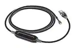
• Set up the Controller without wiring the power supply by
Refer to Safety Precautions on page 50.
connecting to the computer with a Communications Conversion
Cable (sold separately). Setup is easy with the CX-Thermo (sold
separately).
• Easy connections to a PLC with programless communications. Use component communications to link
Temperature Controllers to each other.
Main I/O Functions
Sensor Input
Universal input
• Thermocouple
• Pt
• Analog current/voltage
E5CC
Dual displays: PV/SV
4-digit displays
Control Output 1
• Relay output
• Voltage output (for driving SSR)
• Linear current output
Indication Accuracy
• Thermocouple input:
±0.3% of PV
• Pt input: ±0.2% of PV
• Analog input:
±0.2% of FS
Control Output 2
• None
• Voltage output (for driving SSR)
Sampling Period
• 50 ms
Auxiliary Outputs
Event Inputs
• None
•2
•4
Remote SP Input
• None
•1
• PF (shift) Key
• Temperature status display
• Simple programming
• Independent heating and
cooling PID control
• Changed parameter display
• Display brightness setting
•3
Transfer Output
• None
•1
Serial Communications
• None
• RS-485
This datasheet is provided as a guideline for selecting products.
Be sure to refer to the following manuals for application precautions and other information required for operation before attempting
to use the product.
E5@C Digital Temperature Controllers User’s Manual (Cat. No. H174)
E5@C Digital Temperature Controllers Communications Manual (Cat. No. H175)
2
�E5CC
Model Number Legend and Standard Models
Model Number Legend
E5CC-@@ @ @ @ @ -@@@ (Example: E5CC-RX3A5M-000)
−− − − − − −−−
A
B C D E
F
A
Model
Control outputs
1 and 2
B
C
D
No. of Power
Terminal
auxiliary supply
type
outputs voltage
E
F
Input
type
Options
Meaning
48 × 48 mm
Control output 1
Relay output
Voltage output
(for driving SSR)
Linear current output *2
Voltage output
(for driving SSR)
E5CC
RX
QX
*1 *3 CX
QQ
CQ
Linear current output *2
3
A
D
5
M
*1
000
001
*1
003
*3
004
005
006
007
Control output 2
None
None
None
Voltage output
(for driving SSR)
Voltage output
(for driving SSR)
3 (one common)
100 to 240 VAC
24 VAC/DC
Screw terminals (with cover)
Universal input
Event
Remote Transfer
HB alarm and
Communications
HS alarm
inputs
SP Input output
----------1
--2
----2
(for 3-phase
RS-485
------heaters)
--RS-485
2
--------4
--------2
Provided.
----2
Provided.
---
*1. Options with HB and HS alarms (001 and 003) cannot be selected if a linear current output is selected for the control output.
*2. The control output cannot be used as a transfer output.
*3. Option 004 can be selected only when "CX" is selected for the control outputs.
Heating and Cooling Control
● Using Heating and Cooling Control
A Control Output Assignment
If there is no control output 2, an auxiliary output is used as the cooling control output.
If there is a control output 2, the two control outputs are used for heating and cooling.
(It does not matter which output is used for heating and which output is used for cooling.)
B Control
If PID control is used, you can set PID control separately for heating and cooling.
This allows you to handle control systems with different heating and cooling response characteristics.
3
�E5CC
Optional Products (Order Separately)
USB-Serial Conversion Cable
Model
E58-CIFQ2
Front Covers
Type
Hard Front Cover
Soft Front Cover
Model
Y92A-48H
Y92A-48D
Terminal Covers
CX-Thermo Support Software
Model
E53-COV17
E53-COV23
Model
EST2-2C-MV4
Note: The E53-COV10 cannot be used.
Refer to page 12 for the mounted dimensions.
Waterproof Packing
Model
Y92S-P8
Note: This Waterproof Packing is provided with the Digital
Temperature Controller.
Current Transformers (CTs)
Hole diameter
5.8 mm
12.0 mm
Model
E54-CT1
E54-CT3
Adapter
Model
Y92F-45
Note: Use this Adapter when the panel has already been prepared for
an E5B@ Controller.
Waterproof Cover
Model
Y92A-48N
Mounting Adapter
Model
Y92F-49
Note: This Mounting Adapter is provided with the Digital Temperature
Controller.
DIN Track Mounting Adapter
Model
Y92F-52
4
Note: CX-Thermo version 4.5 or higher is required for the E5CC.
For the system requirements for the CX-Thermo, refer to
information on the EST2-2C-MV4 on the OMRON website
(www.ia.omron.com).
�E5CC
Specifications
Ratings
Power supply voltage
Operating voltage range
Power consumption
Sensor input
Input impedance
Control method
Relay output
Control
output
Auxiliary
output
Voltage output
(for driving SSR)
Linear current output
Number of outputs
Output specifications
Number of inputs
Event input External contact input
specifications
Transfer
output
Number of outputs
Output specifications
Setting method
Remote SP input
Indication method
Multi SP
Bank switching
Other functions
Ambient operating temperature
Ambient operating humidity
Storage temperature
A in model number: 100 to 240 VAC, 50/60 Hz
D in model number: 24 VAC, 50/60 Hz; 24 VDC
85% to 110% of rated supply voltage
Models with option selection of 000: 5.2 VA max. at 100 to 240 VAC, and 3.1 VA max. at 24 VAC or
1.6 W max. at 24 VDC
All other models: 6.5 VA max. at 100 to 240 VAC, and 4.1 VA max. at 24 VAC or 2.3 W max. at 24 VDC
Temperature input
Thermocouple: K, J, T, E, L, U, N, R, S, B, W, or PL II
Platinum resistance thermometer: Pt100 or JPt100
Infrared temperature sensor (ES1B): 10 to 70°C, 60 to 120°C, 115 to 165°C, or 140 to 260°C
Analog input
Current input: 4 to 20 mA or 0 to 20 mA
Voltage input: 1 to 5 V, 0 to 5 V, or 0 to 10 V
Current input: 150 Ω max., Voltage input: 1 MΩ min.
(Use a 1:1 connection when connecting the ES2-HB/THB.)
ON/OFF control or 2-PID control (with auto-tuning)
SPST-NO, 250 VAC, 3 A (resistive load), electrical life: 100,000 operations,
minimum applicable load: 5 V, 10 mA *
Output voltage: 12 VDC ±20% (PNP), max. load current: 21 mA, with short-circuit protection circuit
4 to 20 mA DC/0 to 20 mA DC, load: 500 Ω max., resolution: approx. 10,000*
3
SPST-NO relay outputs, 250 VAC, Models with 3 outputs: 2 A (resistive load),
Electrical life: 100,000 operations, Minimum applicable load: 10 mA at 5 V
2 or 4 (depends on model)
Contact input: ON: 1 kΩ max., OFF: 100 kΩ min.
Non-contact input: ON: Residual voltage: 1.5 V max., OFF: Leakage current: 0.1 mA max.
Current flow: Approx. 7 mA per contact
1 (only on models with a transfer output)
Contact output: 4 to 20 mA DC, load: 500 Ω max., resolution: approx. 10,000
Linear voltage output: 1 to 5 VDC, load: 1 kΩ max, resolution: Approx. 10,000
Digital setting using front panel keys
Current input: 4 to 20 mA DC or 0 to 20 mA DC (input impedance: 150 Ω max.)
Voltage input: 1 to 5 V, 0 to 5 V, or 0 to 10 V (input impedance: 1 MΩ min.)
11-segment digital display and individual indicators
Character height: PV: 15.2 mm, SV: 7.1 mm
Up to eight set points (SP0 to SP7) can be saved and selected using event inputs, key operations, or
serial communications.
None
Manual output, heating/cooling control, loop burnout alarm, SP ramp, other alarm functions, heater
burnout (HB) alarm (including SSR failure (HS) alarm), 40% AT, 100% AT, MV limiter, input digital
filter, self tuning, robust tuning, PV input shift, run/stop, protection functions, extraction of square root,
MV change rate limit, simple calculations, temperature status display, simple programming, moving
average of input value, and display brightness setting
-10 to 55°C (with no condensation or icing),
for 3-year warranty: -10 to 50°C (with no condensation or icing)
25% to 85%
-25 to 65°C (with no condensation or icing)
* You cannot select a relay output or linear current output for control output 2.
5
�E5CC
Input Ranges
●Thermocouple/Platinum Resistance Thermometer (Universal inputs)
Platinum resistance
thermometer
Input type
Name
Pt100
Infrared temperature
sensor
Thermocouple
JPt100
K
J
T
E
L
U
N
R
S
B
W
PLII
10 to
70°C
60 to
120°C
115 to
165°C
120
165
140 to
260°C
2300
2300
1800
1800
1700
1700
1700
1600
1500
Temperature range (°C)
1400
1300
1300
1300
1300
1200
1100
1000
900
850
850
850
800
700
600
600
500.0
500
500.0
500.0
400.0
400
400
400.0
400
400.0
260
300
200
100.0
100
90
100
0
0.0
-100
-200
100.0
-200
-199.9
0
1
Setting
number
0.0
199.9
2
3
-20.0
-100
-20.0
6
7
8
-200
4
5
0
0
16
17
0
0
0
0
0
0
19
20
21
22
23
24
-100
-200
-199.9
-200
9
10
11
12
-200
-199.9
-200
13
14
15
18
Shaded settings are the default settings.
The applicable standards for the input types are as follows:
K, J, T, E, N, R, S, B: JIS C 1602-1995, IEC 60584-1
L: Fe-CuNi, DIN 43710-1985
U: Cu-CuNi, DIN 43710-1985
W: W5Re/W26Re, ASTM E988-1990
JPt100: JIS C 1604-1989, JIS C 1606-1989
Pt100: JIS C 1604-1997, IEC 60751
PL II: According to Platinel II electromotive force charts from BASF (previously Engelhard)
●Analog input
Input type
Input
specification
Current
4 to 20 mA 0 to 20 mA
Voltage
1 to 5 V
0 to 5 V
Usable in the following ranges by scaling:
-1999 to 9999, -199.9 to 999.9,
-19.99 to 99.99 or -1.999 to 9.999
Setting number
25
26
27
28
0 to 10 V
Setting range
6
29
�E5CC
Alarm Outputs
Each alarm can be independently set to one of the following 19 alarm types. The default is 2: Upper limit. (see note.)
Auxiliary outputs are allocated for alarms. ON delays and OFF delays (0 to 999 s) can also be specified.
Note: In the default settings for models with HB or HS alarms, alarm 1 is set to a heater alarm (HA) and the Alarm Type 1 parameter is not displayed.
To use alarm 1, set the output assignment to alarm 1.
Set
value
Alarm type
0
Alarm function OFF
1
Upper- and lower-limit *1
2
Upper-limit
(default)
3
Lower-limit
4
Upper- and lower-limit
range *1
5
6
7
8
9
10
11
Alarm output operation
Description of function
When alarm value X When alarm value X
is positive
is negative
Output OFF
No alarm
Set the upward deviation in the set point for the alarm upper
L H
limit (H) and the lower deviation in the set point for the alarm
ON
*2
OFF
PV
lower limit (L). The alarm is ON when the PV is outside this
SP
deviation range.
Set the upward deviation in the set point by setting the alarm
X
X
ON
ON
value (X). The alarm is ON when the PV is higher than the
OFF
PV
OFF
PV
SP
SP
SP by the deviation or more.
Set the downward deviation in the set point by setting the
X
X
ON
ON
alarm value (X). The alarm is ON when the PV is lower than
OFF
PV
OFF
PV
SP
SP
the SP by the deviation or more.
Set the upward deviation in the set point for the alarm upper
L H
limit (H) and the lower deviation in the set point for the alarm
ON
*3
OFF
PV
lower limit (L). The alarm is ON when the PV is inside this deSP
viation range.
Upper- and lower-limit
with standby sequence *1 *5
Upper-limit with standby
sequence
Lower-limit with standby
sequence
ON
OFF
Absolute-value upper-limit
ON
OFF
Absolute-value lower-limit
ON
OFF
Absolute-value upper-limit with standby sequence
ON
OFF
Absolute-value lower-limit
with standby sequence
ON
OFF
LBA (alarm 1 type only)
PV change rate alarm
14
SP absolute-value
upper-limit alarm
ON
OFF
SP absolute-value
lower-limit alarm
ON
OFF
H
X
SP
PV
ON
OFF
PV
ON
OFF
PV
ON
OFF
PV
ON
OFF
PV
ON
OFF
PV
ON
OFF
X
SP
X
0
X
0
X
0
X
0
ON
OFF
MV absolute-value
upper-limit alarm *9
X
0
ON
OFF
19
A standby sequence is added to the upper-limit alarm (2). *6
PV
A standby sequence is added to the lower-limit alarm (3). *6
X
SP
X
0
PV
X
0
PV
X
0
PV
X
0
PV
ON
OFF
SP
ON
OFF
X
0
The alarm will turn ON if the process value is smaller than the
alarm value (X) regardless of the set point.
A standby sequence is added to the absolute-value upperlimit alarm (8). *6
A standby sequence is added to the absolute-value lowerlimit alarm (9). *6
X
0
SP
X
0
SP
This alarm type turns ON the alarm when the set point (SP)
is higher than the alarm value (X).
This alarm type turns ON the alarm when the set point (SP)
is lower than the alarm value (X).
Standard Control
X
MV
0
The alarm will turn ON if the process value is larger than the
alarm value (X) regardless of the set point.
ON
OFF
X
0
MV
X
MV
0
X
MV
0
Always ON
Standard Control
ON
OFF
X
0
MV
This alarm type turns ON the alarm when the manipulated
Heating/Cooling
Heating/Cooling
variable (MV) is lower than the alarm value (X).
Control (Cooling MV) Control (Cooling MV)
ON
OFF
18
PV
*7
*8
SP
Standard Control
17
SP
This alarm type turns ON the alarm when the manipulated
Heating/Cooling
Heating/Cooling
variable (MV) is higher than the alarm value (X).
Control (Heating MV) Control (Heating MV)
ON
OFF
MV absolute-value
lower-limit alarm *9
X
-
Standard Control
16
A standby sequence is added to the upper- and lower-limit
alarm (1). *6
*4
PV
SP
ON
OFF
12
13
15
L
ON
OFF
RSP absolute-value
upper-limit alarm *10
ON
OFF
RSP absolute-value
lower-limit alarm *10
ON
OFF
X
MV
0
X
0
RSP
ON
OFF
RSP
ON
OFF
X
0
Always ON
X
0
RSP
X
0
RSP
This alarm type turns ON the alarm when the remote SP
(RSP) is higher than the alarm value (X).
This alarm type turns ON the alarm when the remote SP
(RSP) is lower than the alarm value (X).
7
�E5CC
*1
*2
With set values 1, 4 and 5, the upper and lower limit values can be set
independently for each alarm type, and are expressed as “L” and “H.”
Set value: 1, Upper- and lower-limit alarm
Case 2
Case 1
Case 3 (Always ON)
H0, L