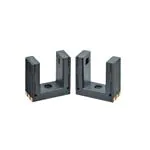
Photomicrosensor (Transmissive)
EE-SX1350
Compact Slot / SMD Type
(Slot width: 5 mm)
• Unique 5 mm Slot width.
• PCB surface mounting type.
• High resolution with a 0.5-mm-wide aperture.
Be sure to read Safety Precautions on page 3.
Ordering Information
Photomicrosensor
Sensing
method
Connecting
method
Transmissive
(slot type)
SMT
Appearance
9
4
9
Sensing distance
5 mm (slot width)
Aperture size (H W)
(mm)
Output type
Model
Emitter 1.4 1.4
Detector 1.4 0.5
Phototransistor
EE-SX1350
Ratings, Characteristics and Exterior Specifications
Absolute Maximum Ratings (Ta = 25°C)
Item
Symbol
Rated value
Unit
Electrical and Optical Characteristics (Ta = 25°C)
Remarks
Item
Forward
current
30
IF
mA
--- *1
Pulse forward
current
IFP
100
mA
Duty ratio:
1%
Puls width:
0.1 ms
Reverse
voltage
VR
4
V
---
Value
Symbol
Emitter
Unit
MIN.
TYP.
MAX.
Emitter
Forward
voltage
VF
---
1.2
1.5
V
IF = 30 mA
Reverse
current
IR
---
0.01
10
A
VR = 4 V
Peak emission
wavelength
P
---
940
---
nm
IF = 20 mA
Light current
IL
0.4
---
4
mA
IF = 20 mA,
VCE = 10 V
Dark current
ID
---
10
200
nA
VCE = 10 V,
0 lx
VCE (sat)
---
0.1
0.4
V
IF = 20 mA,
IL = 0.1 mA
P
---
900
---
nm
VCE = 5 V
Rising time
tr
---
11
---
s
VCC = 5 V,
RL = 100
IL = 1 mA *
Falling time
tf
---
14
---
s
VCC = 5 V,
RL = 100
IL = 1 mA *
Detector
Detector
CollectorEmitter voltage
Condition
12
VCEO
V
---
EmitterCollector
voltage
VECO
5
V
---
Collector
current
IC
20
mA
---
Collector
dissipation
PC
50
mW
--- *1
Topr
-30 to 85
°C
--- *1
Operating
temperature
Storage
temperature
Tstg
-40 to 100
°C
--- *1
Reflow soldering
temperature
Tsol
255
°C
10 sec.
max. *2
*1. Continuous Forward Current and Collector Power Dissipation
must be derated complying. The product should be used without
freezing or condensation.
*2. In case of reflow soldering, conditions which are shown at the
temperature profile should be kept.
Peak spectral
sensitivity
wavelength
* Refer to the following timing diagram for tr and tf.
Input
Input
0
Material
IL
VCC
t
90%
10%
Output
0
Exterior Specifications
Connecting method
CollectorEmitter
saturated
voltage
tr
Output
t
tf
RL
Weight (g)
Case
SMT
0.3
PPS
1
�EE-SX1350
Engineering Data (Reference value)
Fig 1. Forward Current vs. Collector
Dissipation Temperature Rating
Fig 2. Forward Current vs. Forward
Voltage Characteristics (Typical)
60
60
50
50
50
40
40
60
Fig 3. Light Current vs. Forward Current
Characteristics (Typical)
4
Ta = 25ºC
VCE = 5 V
3.5
20
20
10
10
40
3
Ta = 25ºC
Light current IL (mA)
30
Ta =30ºC
Forward current IF (mA)
IF
30
Collector dissipation PC (mW)
Forward current IF (mA)
PC
Ta= 85ºC
30
20
2.5
2
1.5
1
10
0.5
0
-40
-20
0
20
40
60
Ambient temperature Ta (ºC)
0
0
100
80
0
0
0.2
0.4
0.6
0.8
1
1.2
1.4
1.6
1.8
Fig 4. Light Current vs. CollectorEmitter Voltage Characteristics
(Typical)
10
20
30
Forward current IF (mA)
40
50
Fig 5. Relative Light Current vs. Ambient Fig 6. Dark Current vs. Ambient
Temperature Characteristics (Typical)
Temperature Characteristics (Typical)
1000
120
4
VCE = 10 V
0lx
IF = 20 mA
VCE = 5 V
Ta = 25ºC
110
IF = 50 mA
2.5
IF = 40 mA
2
IF = 30 mA
1.5
IF = 20 mA
100
100
Dark current ID (nA)
3
Relative light current IL (%)
3.5
Light current IL (mA)
0
Forward voltage VF (V)
90
80
10
1
1
70
IF = 10 mA
0.5
IF = 5 mA
0.1
-30 -20 -10
60
0
-40
0
1
2
3
4
5
6
7
8
Collector-Emitter voltage VCE (V)
9
-20
10
Fig 7. Response Time vs. Load
Resistance Characteristics (Typical)
0
20
40
60
80
100
Ambient temperature Ta (ºC)
0 10 20 30 40 50 60 70 80 90
Ambient temperature Ta (ºC)
Fig 8. Sensing Position Characteristics Fig 9. Sensing Position Characteristics
(Typical)
(Typical)
10,000
VCC = 5 V
IL =1 mA
Ta = 25ºC
120%
120%
100%
100%
100
tf
10
tr
1
0.01
0.1
1
Load resistance RL (kΩ)
Relative light current IL (%)
Relative light current IL (%)
Response time tr, tf (μs)
1,000
80%
60%
IF = 20 mA
VCE = 5 V
Ta = 25ºC
(Center of
optical axis)
40%
20%
10
0%
-1
80%
60%
IF = 20 mA
VCE = 5 V
Ta = 25ºC
40%
(Center of
optical axis)
20%
0%
-0.75
-0.5
-0.25
0
0.25
Distance d (mm)
0.5
0.75
1
-2
-1.5
-1
-0.5
0
0.5
Distance d (mm)
1
1.5
2
2
�EE-SX1350
Safety Precautions
To ensure safe operation, be sure to read and follow the Instruction Manual provided with the Sensor.
CAUTION
Precautions for Correct Use
Do not use the product in atmospheres or
environments that exceed product ratings.
This product is for surface mounting. Refer to
Soldering Information, Storage and Baking for
details.
Dispose of this product as industrial waste.
This product is not designed or rated for ensuring
safety of persons either directly or indirectly. Do not
use it for such purposes.
Precautions for Safe Use
Do not use the product with a voltage or current
that exceeds the rated range.
Applying a voltage or current that is higher than the rated range may
result in explosion or fire.
Do not miswire such as the polarity of the power
supply voltage.
Otherwise the product may be damaged or it may burn.
This product does not resist water. Do not use
the product in places where water or oil may be
sprayed onto the product.
Dimensions and Internal Circuit
(Unit: mm)
Photomicrosensor
Ejector pin, gate mark, or flat surface
2.0 mm dia. or 0.5 mm recess (MAX)
(1)
(2)
(3)
(6)
(5)
(4)
4
(6
xC
0.
2)
EE-SX1350
9
Marking
(upper: model, lower: lot No.)
1.4 0.5
A B
0.5 ±0.15
7
Detector
Terminals are exposed
in the end face of the board
2
9
Emitter
1.5
1.4
1.5
1.4
Aperture size (H x W)
1.4 1.4
5 ±0.2
Optical axis
1.5
1.4
Terminals are exposed
in the end face of the board
R0.3
1
1
1
(0.4)
A B
1
Cross section view
B-B
1
R0.3
(0.4)
1
Cross section view
A-A
1
1
2.8
0.4
2.8
1
Internal circuit
1
Top view
(6)
(2)
(5)
(3)
(4)
Terminal No.
2
7
2
0.4
1
(1)
Name
(1)
Anode
(2)
Not connected.
(3)
Cathode
(4)
Collector
(5)
Not connected.
(6)
Emitter
Unless otherwise specified, the tolerances are ±0.2 mm.
3
�EE-SX1350
Tape and Reel
Reel (Unit: mm) *
21±0.8 dia.
2±0.5
13±0.2 dia.
80±1dia. 330±2 dia.
Product name
PHOTO MICROSENSOR
Lot number
Quantity
Country of origin
W1 = 17.5±1
W2 = 21.5±1
W1
W2
Tape (Unit: mm)
16
1.5 dia.
1.75
2
0.4
16
(4.3)
7.5
4
(9.3)
(9.1)
C
K
E
A
Tape Pull-out direction
Note: Direction of product packing is upper figure.
Tape quantity
400 pcs./reel
50 pcs./pack *
* EE-SX1350-1 (50 pcs./pack) has no reel, only tape is attached.
4
�EE-SX1350
Soldering Information
Reflow soldering : Temperature profile
Manual soldering
1. The reflow soldering can be implemented in two times complying
with the following diagram.
All the temperatures in the product must be within the diagram.
2. The recommended thickness of the metal mask for screen printing
is between 0.2 and 0.25 mm.
The manual soldering should not be applied to the products,
otherwise the housing may be deformed and/or the Au plating may be
peeled off by heat.
260°C max.
255°C
Temperature (°C)
1 to 4°C/s
230°C
10 sec max.
150 to 180°C max.
1 to 4°C/sec
40 sec max.
1 to 4°C/s
120 sec max.
Other notes
The use of infrared lamp causes the temperature at the resin to rise
particularly too high.
All the temperatures in the product must be within the above diagram.
Do not immerse the resin part into the solder. Even if within the above
temperature diagram, there is a possibility that the gold wire in the
products is broken in case that the deformation of PC board gives
stress to the products.
Please confirm the conditions (including material and method of flux
and cleaning) of the reflow soldering fully by actual solder reflow
machine prior to the mass production use.
Time (s)
Storage
Storage conditions
Treatment after open
To protect the product from the effects of humidity until the package
is opened, dry-box storage is recommended. If this is not possible,
store the product under the following conditions:
Temperature: 10 to 30 °C
Humidity: 60% RH max.
1. Reflow soldering must be done within 48 hours stored at the
conditions of humidity 60% RH or less and temperature 10 to
30°C.
2. If the product must be stored after it is unpacked, store it in a dry
box or reseal it in a moisture-proof package with desiccant at a
temperature of 10 to 30°C and a humidity of 60% RH or less. Even
then, mount the product within one week.
Baking
In case that it could not carry out the above treatment, it is able to
mount by the following baking treatment. However baking treatment
shall be limited only 1 time.
Recommended conditions: 60°C for 24 to 48 hours (reeled one)
100°C for 8 to 24 hours (loose one)
5
�• Application examples provided in this document are for reference only. In actual applications, confirm equipment functions and safety before using the product.
• Consult your OMRON representative before using the product under conditions which are not described in the manual or applying the product to nuclear control systems, railroad
systems, aviation systems, vehicles, combustion systems, medical equipment, amusement machines, safety equipment, and other systems or equipment that may have a serious
influence on lives and property if used improperly. Make sure that the ratings and performance characteristics of the product provide a margin of safety for the system or
equipment, and be sure to provide the system or equipment with double safety mechanisms.
Note: Do not use this document to operate the Unit.
OMRON Corporation
Electronic and Mechanical Components Company
Contact: www.omron.com/ecb
Cat. No. E457-E1-05
0417(0816)(O)
�
很抱歉,暂时无法提供与“EE-SX1350”相匹配的价格&库存,您可以联系我们找货
免费人工找货- 国内价格
- 1+9.70920
- 10+8.18640
- 30+7.35480
- 100+6.41520
- 400+5.99400
- 800+5.81040