### 物料型号
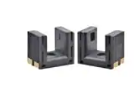
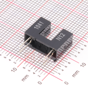
- EE-SX670A/R:标准型,透射式,5mm槽宽,9mm槽深。
- EE-SX671A/R:L型。
- EE-SX672A/R:T型。
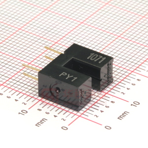
- EE-SX673A/R:密装型,透射式,5mm槽宽。
- EE-SX674A/R:密装型,透射式。
### 器件简介
EE-SX670/671/672/673/674A/R系列为带有Dark-ON指示的光电传感器,具有PNP输出的新型号现已可用。这些传感器可以实现高达1kHz的响应频率,并且工作电压范围宽(5至24VDC),可以与TTL、继电器和可编程控制器(PLC)平滑连接。
### 引脚分配
- Vcc(1):电源正极。
- L(2):轻触开关或PNP输出型号的集电极。
- OUT(3):输出。
- GND(0V)(4):地。
### 参数特性
- 供电电压:5至24VDC ±10%,纹波(p-p)不超过10%。
- 功耗:NPN型号最大35mA,PNP型号最大30mA。
- 槽宽:5mm。
- 标准参照物:不透明物体,2x0.8mm。
- 差分距离:0.025mm。
- 控制输出:NPN开集输出型号在5至24VDC下可驱动100mA负载电流,PNP型号可驱动50mA负载电流。
### 功能详解
这些传感器可以直接切换高达100mA的负载(NPN版本)。它们集成了电路,并采用坚固的玻璃纤维增强PBT树脂制成的模塑外壳。传感器可以配置为Light-ON或Dark-ON操作,具体取决于L端和正极(+)端是否连接。
### 应用信息
适用于需要检测物体存在或不存在的应用场合,如自动化控制、机器人技术、安防系统等。
### 封装信息
- 外壳材料:聚丁烯对苯二甲酸酯(PBT)。
- 覆盖材料:聚碳酸酯(PC)。
- 发射/接收器:聚碳酸酯(PC)。
- 连接器:EE-1001/1006连接器;焊接端子。